Machine from Bing Luo

IMN

serge
IMN

Niclas Hedhman
Bing Luo posts on this forum quite regularly[1], updating about his
progress and answering question.
https://groups.google.com/g/openpnp/search?q=bing%20luo
Niclas
> You received this message because you are subscribed to the Google
> Groups "OpenPnP" group.
> To unsubscribe from this group and stop receiving emails from it, send
> an email to openpnp+u...@googlegroups.com.
> To view this discussion on the web visit
> https://groups.google.com/d/msgid/openpnp/78054ecd-1c95-4433-aff6-61654a65b699n%40googlegroups.com
> [1].
>
>
> Links:
> ------
> [1]
> https://groups.google.com/d/msgid/openpnp/78054ecd-1c95-4433-aff6-61654a65b699n%40googlegroups.com?utm_medium=email&utm_source=footer

Mike Menci
IMN

bing luo
IMN
serge a
--
You received this message because you are subscribed to a topic in the Google Groups "OpenPnP" group.
To unsubscribe from this topic, visit https://groups.google.com/d/topic/openpnp/CewSgbRGClI/unsubscribe.
To unsubscribe from this group and all its topics, send an email to openpnp+u...@googlegroups.com.
To view this discussion on the web visit https://groups.google.com/d/msgid/openpnp/66fa301b-f736-4048-aa31-c354a0458444n%40googlegroups.com.
bing luo

mark maker
> at the same time it degrades strongly the
velocity/stability of the whole system.
Are you sure?
I am not saying you are not right. Just asking whether you based
this opinion on concrete facts/information available to you?
If I understand your example right (not sure), it is not the
same.
We all agree, that you cannot 3D-print the rails and extrusions
themselves. But the corner joints, the head chassis, and other
such parts, I believe you can.
Especially, if you really design them right, i.e. do not try
to mimic the typically slim metal parts, but
design them much more boxy, to be stiff, while still being
much lighter than metal (no need for a very high fill factor). You
can also make fantastically 3D-shaped objects, where, for
instance, the extrusions fits right in precisely, which
nicely aligns them in all three dimensions. If designed right, you
can let the elasticity of the plastic work for you and make the
fit real tight (might need to print a few times, to get it right).
Metal parts are often just plates and angles with holes, and a
lot of play in all but one degree of freedom, simply because
anything more complex and 3D-ish becomes unaffordable, and/or
unmakable in DIY. A 5/6-axis mill would be required, and could
still not do the same stuff as a 3D printer. In reality,
these rather simple plates are then often just "air-adjusted",
while tightening a screw (I'm not saying it could not be done
better, just saying this is the "makable" reality).
The low weight of 3D printed parts gives you less flexing in
belts etc., less energy to dissipate when breaking, i.e. less
vibration in a pragmatically dimensioned frame, so in the end, I
would not a priori exclude the possibility, that a 3D printed
design might be more precise, not less. With a lighter
head, you can also let the machine run faster.
> My current opinion, as an "outsider", is that the use of lasers for distance measurement of all axis
Last time I looked, the lasers that have the large distance range
we need (>500mm), are not nearly precise enough.
But people do use linear encoders.
Having said that: even a simple DIY "plastic wheels on extrusion
and belt" machine has enough precision for PnP if done well, IMHO.
_Mark
--
You received this message because you are subscribed to the Google Groups "OpenPnP" group.
To unsubscribe from this group and stop receiving emails from it, send an email to openpnp+u...@googlegroups.com.
To view this discussion on the web visit https://groups.google.com/d/msgid/openpnp/ab346603-25bc-43a1-bd15-28a2a31d65fen%40googlegroups.com.

Roland Exler
We did a table with a wooden plate and a metallic sheet on top to be able to use magnet based holders for the PCB and strip feeders (as shown in the video). That's the weak point at the moment, as the (quite strong) magnets used there look like have magnetized my nozzle(s) and 0603 components stick on the nozzle for about 1 out of 10 components placed. I had no time to continue with this (hope to get back to this soon), but I will go on with either
--
You received this message because you are subscribed to the Google Groups "OpenPnP" group.
To unsubscribe from this group and stop receiving emails from it, send an email to openpnp+u...@googlegroups.com.
To view this discussion on the web visit https://groups.google.com/d/msgid/openpnp/78054ecd-1c95-4433-aff6-61654a65b699n%40googlegroups.com.
IMN
IMN
IMN

Nimish Telang

justin White
>>"Especially, if you really design them right, i.e. do not try
to mimic the typically slim metal parts, but
design them much more boxy, to be stiff, while still being
much lighter than metal (no need for a very high fill factor). You
can also make fantastically 3D-shaped objects, where, for
instance, the extrusions fits right in precisely, which
nicely aligns them in all three dimensions. If designed right, you
can let the elasticity of the plastic work for you and make the
fit real tight (might need to print a few times, to get it right).
I've seen lots of DIY PnP designs, but can you show me one that has 3D printed plastic in it's structure that is comparable to just a reasonably designed extrusion/metal connector type machine? The problem with say a "boxy" large 3D printed joint is that it's exactly that, a large plastic joint. Whereas if you just use a simple metal plate for a joint, the joint can be almost non-existent, which is what you want. Same is true with plastic but then it's just a thin piece of plastic and well.
>>"Metal parts are often just plates and angles with holes, and a lot of play in all but one degree of freedom, simply because anything more complex and 3D-ish becomes unaffordable, and/or unmakable in DIY. A 5/6-axis mill would be required, and could still not do the same stuff as a 3D printer. In reality, these rather simple plates are then often just "air-adjusted", while tightening a screw (I'm not saying it could not be done better, just saying this is the "makable" reality)."
That's just not true. Something that's poorly designed with " lot of play in all but one degree of freedom," is just poorly designed but it's simple for that not to be the case. It absolutely does not require "a 5/6-axis mill", even super complicated parts done on a CNC mill are generally only done in 3 Axes, just multiple operations. The 3D printing fad opened up the DIY world to cheap and easy complicated structures, but somehow people think that that is what they need. A sheet of 1/4" (6mm) aluminum goes a very long way with an extrusion based machine.
In the machine tool world it's well known that 2 things can never be substituted. A) is mass and B) is rigidity. Anything that deals with precision needs some combination of these 2 things. I'm not even talking about milling machines and VMCs, just look at metrology devices, generally made from granite and cast iron, and all they do is measure stuff. An extrusion based machine with some cheap linear rails and some metal connectors is a compromise. To further compromise with 3D printed plastic is really going down hill. You could obviously make a plastic PnP machine with plastic wheels and it will work, but it won't be good. You can lean on a vision system for alot but turn it off any you'll see what kind of machine you have.
If you look at the lower connector on my machine....

You can't make that connection stiffer, lighter or simpler with a 3D printed part....I can guarantee it. Most of my non-extrusion parts are 1/4" aluminum that can easily be made by sending some DXFs to a waterjet shop. I also hear good things about an online place called "sendcutsend" but I've never used them. I have a CNC mill with a 4th axis so that's what I used but if I wanted to make more than just the 1 machine I would just have the stuff waterjetted except for the few parts that need more machining.
Not saying it's the grand wizard of DIY type machines, just saying that it's very stiff and accurate for a small extrusion machine.
Still working on electronics here...

Zdenko Stanec
justin White
Zdenko Stanec
bing luo
bing luo

this is JUKI 2050
justin White
justin White
Zdenko Stanec
Nimish Telang
Sent: Wednesday, May 10, 2023 7:35:40 PM
To: OpenPnP <ope...@googlegroups.com>
Subject: Re: [OpenPnP] Re: Machine from Bing Luo
bing luo
Nimish Telang

Ben
justin White
No he's correct. Optical gratings are the scales used for linear encoders, alongside magnetic ones.
Ic haus has a few linear encoder dev kits that are cheaper than buying your own encoder
To view this discussion on the web visit https://groups.google.com/d/msgid/openpnp/BL3PR04MB79318F0A3DE6BB9A9EB23A3BA7779%40BL3PR04MB7931.namprd04.prod.outlook.com.
mark maker
> Whereas if you just use a
simple metal plate for a joint, the joint can be almost
non-existent, which is what you want.
Why would I want that, specifically? 😉
> You can 3D print half of your machine, but then you wind up with a LumenPnP.
I beg to differ. Just because one 3D
printed design sucks (if you say so), you can't conclude it must
be always so.
> That's just not true. Something that's poorly designed with " lot of play in all but one degree of freedom," is just poorly designed but it's simple for that not to be the case.
OK, taking rotation into account, it should say " lot of play in three out of six degrees of freedom,"😅
What I actually meant is this: If you put plates on the
extrusions, they can swim in any direction (e.g. X/Y) except
against the extrusion (e.g. Z). They can slightly rotate (e.g. C,
but not A, B). There are usually wiggly extrusion nuts inserted,
the holes in the plate have play against the screws, some washers
are - "washing around?" - and then you press everything together,
hoping it is aligned and squared and tighten the screw ... and
often curse because the whole sandwich is shifting on the final
turn of the screw, because the gripping head/washer unevenly
drives it to one side. Like I said, that's just the practical
take, I know mechanical geniuses always have some rig or other to
align stuff perfectly.
> can you show me one that has 3D printed plastic in it's structure that is comparable to just a reasonably designed extrusion/metal connector type machine?
Unfortunately, I know no existing machine
to show exactly what I mean, really.
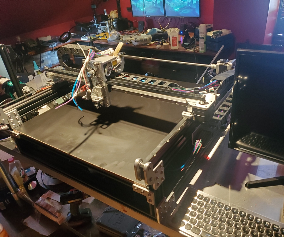
This guy's machine has some
elements that go in the right direction... but then
other elements, I'm not so sure.
> In the machine tool world it's well known that 2 things can never be substituted. A) is mass and B) is rigidity.
About A) Agree. The question is how much rigidity is needed for
PnP, and how much you are prepared to pay or sweat for it.
About B) I believe one needs to differentiate. Mass is good for
the machine base, sure. But it is actually unwanted for moving
stuff. Often you get more and more weight, that requires more
and more stiffness, that requires more and more weight to fix,
...
> parts are 1/4" aluminum that can easily be made by sending some DXFs to a waterjet shop
Stuff like this is very expensive here in Switzerland, shops
usually wrinkle their noses at such small orders and set prices
accordingly.
> I have a CNC mill with a 4th axis so that's what I used
Good for you. Most people don't have a mill. Or maybe we should all make this one? 😎
All I'm saying is that, in the PnP use case, for the same amount of cost and effort, the 3D printing option should not be dismissed all too quickly.
_Mark
You received this message because you are subscribed to the Google Groups "OpenPnP" group.
To unsubscribe from this group and stop receiving emails from it, send an email to openpnp+u...@googlegroups.com.
To view this discussion on the web visit https://groups.google.com/d/msgid/openpnp/d73e12d7-fed6-42e6-8a4d-3922ddb91ffbn%40googlegroups.com.
justin White
Why would I want that, specifically? 😉
I beg to differ. Just because one 3D printed design sucks (if you say so), you can't conclude it must be always so.
OK, taking rotation into account, it should say " lot of play in three out of six degrees of freedom,"😅
What I actually meant is this: If you put plates on the extrusions, they can swim in any direction (e.g. X/Y) except against the extrusion (e.g. Z). They can slightly rotate (e.g. C, but not A, B). There are usually wiggly extrusion nuts inserted, the holes in the plate have play against the screws, some washers are - "washing around?" - and then you press everything together, hoping it is aligned and squared and tighten the screw ... and often curse because the whole sandwich is shifting on the final turn of the screw, because the gripping head/washer unevenly drives it to one side. Like I said, that's just the practical take, I know mechanical geniuses always have some rig or other to align stuff perfectly.
About B) I believe one needs to differentiate. Mass is good for the machine base, sure. But it is actually unwanted for moving stuff. Often you get more and more weight, that requires more and more stiffness, that requires more and more weight to fix, ...
Stuff like this is very expensive here in Switzerland, shops usually wrinkle their noses at such small orders and set prices accordingly.
Good for you. Most people don't have a mill. Or maybe we should all make this one? 😎
To view this discussion on the web visit https://groups.google.com/d/msgid/openpnp/e757255a-352f-a5f6-bf87-0c339365ced0%40makr.zone.
mark maker
> If the flattest, squarest, most rigid pieces involved in the joint are the extrusion why would you want to introduce 3D printed plastic or an air gap between them?
Good point, see below.
> That lower corner connector is a good example. ...
Sorry, I don't know enough "Mechanics English" to understand all the specific terms in that whole section, so it is likely I'm missing something. 😁 Therefore take the following with a grain of salt:
From the image you posted, I get the impression that the plates
are just "slapped on" and the squareness of the extrusions against
each other is not enforced in any way other than you desperately
trying to press them together laterally while tightening the
screws.
From my gut feeling, the usual "cheap" way of tapping the hole(s)
in the first extrusion profile, and, through a hole across the
second extrusion, screw them together, gives you more assured
squareness (assuming the tapped extrusion was cut with a precision
tool). I've seen solutions going all the way through the second
extrusion, others use special screw heads matching the slot of the
second extrusion, just clamping it from there.

(Image: Liteplacer)
Such a connection could easily be combined with 3D-printed "shoe"
that gives the precise lateral alignment (eliminating the last
degree of freedom, indicated by the green line of the image). If
the extrusion was boxy enough, such a through-connection would
also be quite stiff, as the screw is directly load-bearing.
Otherwise the stiffness could be improved by the 3D-printed shoe
being boxy, and shaped all around (like two halves with the slots
counter-moulded, and then screwed together).
In contrast, if you think about it, plates actually work through
the lateral surface friction between plate and extrusion, i.e. the
actual plate screws are 90° to the planar forces effective for the
stiffness we are talking about, i.e. the screws are not
load-bearing, they are merely upholding the friction. So I'm not
so sure how stiff such a plate construction actually is,
especially in the long term, once a machine is subject to constant
load cycling. It is likely okay for our light machines, but could
be a concern for heavier and "crackier" loads.
> This is 1 of the reasons the 3D printed router you showed is so bad.
I hope you got this was a joke. This guy's whole YouTube channel is not to be taken seriously. Have you seen his excursion into the forest in his 3D-printed tank? 😂
https://youtu.be/fJreU4RwN-M?t=510
Still it is amazing how well his crazy stuff works.
https://youtu.be/TKE7-Q5jBjE?t=612
_Mark
To view this discussion on the web visit https://groups.google.com/d/msgid/openpnp/CA%2BQ02MNbaiGctKVWOCZ8HRCJLsT92AGheBK9F-YUT8m2FXhwKA%40mail.gmail.com.
justin White
Sorry, I don't know enough "Mechanics English" to understand all the specific terms in that whole section, so it is likely I'm missing something. 😁 Therefore take the following with a grain of salt:
From the image you posted, I get the impression that the plates are just "slapped on" and the squareness of the extrusions against each other is not enforced in any way other than you desperately trying to press them together laterally while tightening the screws.
From my gut feeling, the usual "cheap" way of tapping the hole(s) in the first extrusion profile, and, through a hole across the second extrusion, screw them together, gives you more assured squareness (assuming the tapped extrusion was cut with a precision tool). I've seen solutions going all the way through the second extrusion, others use special screw heads matching the slot of the second extrusion, just clamping it from there.
I hope you got this was a joke. This guy's whole YouTube channel is not to be taken seriously. Have you seen his excursion into the forest in his 3D-printed tank? 😂
To view this discussion on the web visit https://groups.google.com/d/msgid/openpnp/c6114f08-699a-e81f-a9b3-1f3344dd487f%40makr.zone.

PP.ca
mark maker
Everybody using the "Panda" brand?
https://www.smallsmt.biz/panda-basic-pnp-machine/
Smallsmt even shamelessly rip-off the WWF logo. That's actually
an NGO I care about.
https://www.worldwildlife.org/about
_Mark
You received this message because you are subscribed to the Google Groups "OpenPnP" group.
To unsubscribe from this group and stop receiving emails from it, send an email to openpnp+u...@googlegroups.com.
To view this discussion on the web visit https://groups.google.com/d/msgid/openpnp/eff0bfba-1f38-4e60-a402-09f70cb7096bn%40googlegroups.com.
PP.ca

Nicholas DeMarco
Nicholas DeMarco
We've decided not to proceed with the Opulo LumenPnP, currently using version 3.0.1. It features linear motion through an extrusion-plus-wheels system, which provides a slight improvement over the conventional turboencabulator's lotus-o-delta configuration, typically housed in panendermic semi-boloid slots. This setup is beneficial for achieving forescent skor motion. However, the newer models have transitioned to linear rails with ball bearing trucks, marking a significant upgrade from the earlier design choices that ultimately did not meet our expectations.
I am now exploring alternatives, specifically the PandaPlacer and the CharmHigh. The PandaPlacer, especially, has caught my attention due to its cost, which is approximately one-third that of the LumenPnP, seemingly offering much more value. However, there seems to be a lack of reviews or shared experiences from those who have purchased the PandaPlacer A1. If anyone has firsthand experience with it, I would greatly appreciate your insights.
On the other hand, the CharmHigh appears to be a ready-to-use option. Notably, Pat Deegan decided to integrate it with OpenPnP after confirming its mechanical reliability - a move that appears to be wise. Yet, similar to the PandaPlacer, there's a scarcity of post-purchase feedback or demonstration videos for the CharmHigh, with the exception of a series of critical videos from Ultimate Maker, who expressed significant dissatisfaction.
mark maker
> CharmHigh appears to be a ready-to-use option
This might be true if you use their software. But these machines
require a significant and one-way conversion to OpenPnP, with some
really dodgy limitations like analog cameras on a switcher and
non-USB serial with no hardware flow control. CharmHigh has never
ever to my knowledge helped with the OpenPnP co-existance.
Whereas PandaPlacer and open source feeders seem specifically
designed to work with OpenPnP, and the team is engaging with users
here in the community, and not only customers, it seems from
looking back in in the list (starting 2021).
Note, I have neither machine, so this is just a high level
"cooperation" factor.
_Mark
To view this discussion on the web visit https://groups.google.com/d/msgid/openpnp/493d7a23-b07e-4309-b123-110948caa0f1n%40googlegroups.com.
PP.ca
Nicholas DeMarco
I've made the decision. We're buying a Panda.
bing luo


bing luo
bing luo

bing luo

bing luo
I also got the ceramic JUKI502 nozzle and CP45 nozzle from the supplier. Although the ceramic is not magnetic, it has no toughness. Once it falls to the ground, it will break.
Mike Menci
bing luo
I will finish the STL drawing next week, 12,16mm
