Vacuum setup

bobgee...@gmail.com
I am just about to go and fetch my nozzle holders from the postage depot. These are the last parts I need (I hope) so am about to start the wiring and software setup.
Huge thanks to Matt and Daniel for making me some of the custom parts, 100% couldn't have got where I am without you guys.
I have fairly closely followed the BOM for Anthony's design and have built everything.
I have some questions about how to setup the vacuum.
I purchased two of the robot digg solenoids. I can't find any info on how to setup the vac apart from this link:
https://github.com/openpnp/openpnp-openbuilds/wiki/Build-Instructions
They are using 4 solenoids and not the same as mine:
I have 2 of these:
http://www.robotdigg.com/product/566/High-frequency-Solenoid-Valve-24VDC
With 4 I am supposed to connect like this:
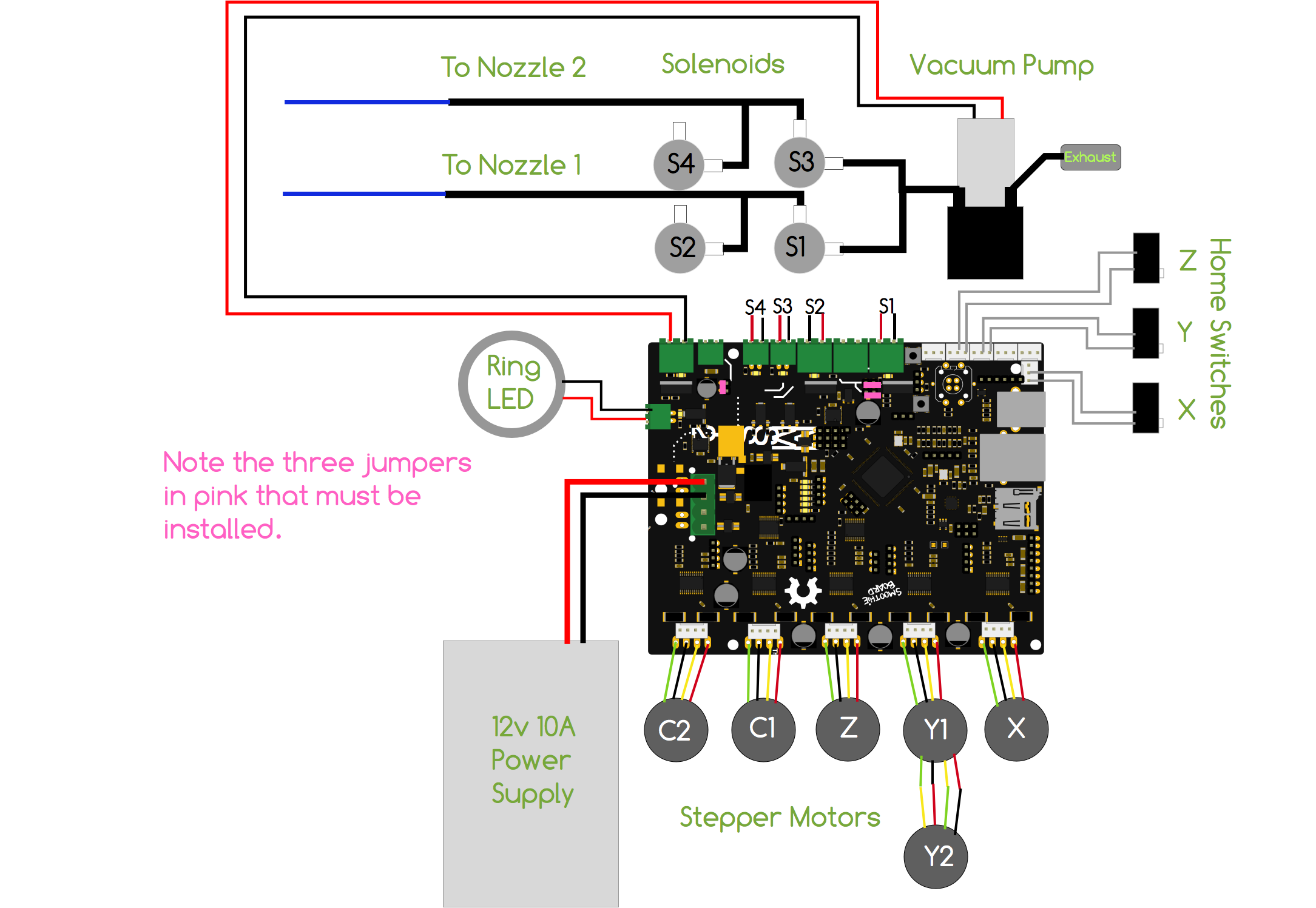
How do I connect 2? Can I use 2?
Also, from the same link on the github, they say you should attach flyback diodes.
My solenoids have wires coming out of them and go straight to the smoothieboard, can I put the diodes accroos teh back of the terminal block where I attach the solenoids to the smoothieboard?
Do I need the flyback diodes?
Any help much appreciated!

Reiner Schmidt

BZHEX
Diodes are good to use whenever you have inductive loads ( coils, motors etc ) on MosFETs. Some MosFET have internal diodes, but it is safer to use external. Yes, you can connect them to terminal block.

evilwulfie
Hey everyone.
I am just about to go and fetch my nozzle holders from the postage depot. These are the last parts I need (I hope) so am about to start the wiring and software setup.
Huge thanks to Matt and Daniel for making me some of the custom parts, 100% couldn't have got where I am without you guys.
I have fairly closely followed the BOM for Anthony's design and have built everything.
I have some questions about how to setup the vacuum.
I purchased two of the robot digg solenoids. I can't find any info on how to setup the vac apart from this link:
https://github.com/openpnp/openpnp-openbuilds/wiki/Build-Instructions
They are using 4 solenoids and not the same as mine:
I have 2 of these:
http://www.robotdigg.com/product/566/High-frequency-Solenoid-Valve-24VDC
With 4 I am supposed to connect like this:
How do I connect 2? Can I use 2?
exhaust port has a little screen and goes to open air, vacuum port goes to pump and input goes to the head.
Also, from the same link on the github, they say you should attach flyback diodes.
My solenoids have wires coming out of them and go straight to the smoothieboard, can I put the diodes accroos teh back of the terminal block where I attach the solenoids to the smoothieboard?
Do I need the flyback diodes?
--
Any help much appreciated!
You received this message because you are subscribed to the Google Groups "OpenPnP" group.
To unsubscribe from this group and stop receiving emails from it, send an email to openpnp+u...@googlegroups.com.
To post to this group, send email to ope...@googlegroups.com.
To view this discussion on the web visit https://groups.google.com/d/msgid/openpnp/063eb8a6-b645-4ccf-964d-9e38eece663e%40googlegroups.com.
For more options, visit https://groups.google.com/d/optout.

Rich Obermeyer
To view this discussion on the web visit https://groups.google.com/d/msgid/openpnp/4814afc6-19c0-5ecd-73b3-eb9c6605f2fb%40gmail.com.
bobgee...@gmail.com
Just realised I don't have any 1N4001 diodes lying around. I do have some 1N4004 and 1N1587 diodes.
I guess the 1N4004 are the closest match and would work fine, but does anyone reading this have a strong opinion on how to proceed?
Cheers
evilwulfie
--
You received this message because you are subscribed to the Google Groups "OpenPnP" group.
To unsubscribe from this group and stop receiving emails from it, send an email to openpnp+u...@googlegroups.com.
To post to this group, send email to ope...@googlegroups.com.
To view this discussion on the web visit https://groups.google.com/d/msgid/openpnp/31a84471-0c62-4ede-8620-5672dc779569%40googlegroups.com.
bobgee...@gmail.com

Michael Anton
Rich Obermeyer
Which PNP controller has that MOSFETs in them?
> On Jan 28, 2017, at 5:46 PM, Michael Anton <3d.m...@gmail.com> wrote:
>
> IRFZ44

SMdude
I really need to think about doing a head mounted controller, there are too many wires!
bobgee...@gmail.com
The solenoid from robotdigg has two grey wires and no obvious polarity marked on it. Does it matter which it is wired, if so, how do I tell?
SMdude
Final question?? !! Haha! :D ;) There's always another one!
bobgee...@gmail.com
Thanks a bunch, that's what I expected but good to get a second opinion.
Not really about the vacuum, but another question about wiring springs to mind. Technically, that's not another question on this topic, so I am still on track!
I guess most people are using the robotdigg Nema-8 motors with yellow, green, red and black wires? Could someone please tell me which way to wire these to the smoothieboard motor connectors? Am I right you just need to put the pairs for each coil side by side, but in no particular order? If so, which are paired? Usually green and red are a pair right? My other motors have a blue, not a black is the only reason I am not sure.
Thanks
SMdude
bobgee...@gmail.com
Cheers, that helps.
So they show blue, yellow, green then red. For the robot digg motor, do I jsut swap blue for black or are the other colours different also?
Thanks
Michael Anton
SMdude

Oz-Ron
Michael & Maddog,
You are both correct and both wrong at the same time. Deuce!
Can we please keep Jasons OpenPnP forum civil (and especially friendly).
Jason works his ring off on this project (and supporting it) so I am sure he doesn’t need this kind of distraction seeping in.
Please continue to revert to constructive, informative & fun stuff in the name of Team OpenPnP!
Thank you,
Ron
Rich Obermeyer
--
You received this message because you are subscribed to the Google Groups "OpenPnP" group.
To unsubscribe from this group and stop receiving emails from it, send an email to openpnp+u...@googlegroups.com.
To post to this group, send email to ope...@googlegroups.com.
To view this discussion on the web visit https://groups.google.com/d/msgid/openpnp/3d11977a-ddfd-4cfd-9c41-979a294ffc7f%40googlegroups.com.
Michael Anton
Michael Anton
Oz-Ron
OK, very glad to be proven wrong - once again. It is fantastic that this forum is friendly and wealth of helpful information shared.
Back to the subject, and my 2 cents:
It is good practise to put the back EMF suppression diode close to the inductor (in this case the valve) as it helps reduce radiated EMI. On equipment like our PnP machines EMI can be a source of unexplained malfunction so anything that minimises the interference is worth incorporating. (If you rely only on the Mosfet body Avalanche / Zener diode without any diode to the positive rail at the coil then the energy in the coil is radiated Marconi style on the way back to the switching device.) Many automotive relays have diodes & resistors incorporated for this reason.
The type of diode *could* be almost any diode, except if using a signal diode then it is best to add a low ohm resistor (~10R) in series to limit the current. Another consideration is when clamping a PWM controlled load back EMF, the switching frequency may dictate the need for a fast recovery diode otherwise the diode will dissipate excessive current. For a straight on/off situation like the pick valve, I agree, in my experience a 1N4001 or 1N4004 is all you need.
Cheers,
Ron
Michael Anton
Michael Anton
On Tuesday, January 31, 2017 at 4:12:38 AM UTC-7, Oz-Ron wrote: