RepoPNP Auto Feeders, McuOnEclipse & NXP K20 Programming

919 views
Skip to first unread message

John deGlavina

unread,
Mar 12, 2020, 8:47:42 AM3/12/20
to OpenPnP
I've been looking for a more robust feeder solution for a while now, and I forgot about this one, which I originally saw on the McuOnEclipse OpenPNP machine. 


These will be able to do exactly what I want. However they're programmed on a platform that I'm not familiar with. The 32bit NXP K20's and K22's. It looks like the software here is slightly more up to date


Does anyone have experience with these feeders and/or controller (tinyK20)? 


Duncan Ellison

unread,
Mar 12, 2020, 10:37:28 AM3/12/20
to OpenPnP
Hello John,

I quickly realised on my OpenPnP journey that the most challenging items would be the head and the feeders and also that stuck down pieces of tape just weren't going to be a viable solution for me.

I solved the head issue with the 'China head' discussed elsewhere here and replaced the nozzle holders with the ones from Peter Betz,  BTW, I also substituted my 3D printed brackets with Peter's superbly made milled aluminium ones and it made a huge difference to the machine.

Anyhow back to feeders, I did quite a lot of research on DIY feeders and somehow the 3D printed 'rubber band and spring' types just didn't strike me as a viable option for a semi-production machine.  The design by Simon Huber (one of Eric Styger's) students seemed to be the best documented and well thought through option and I felt it gave me the best chance of producing something that I could actually use long term.  I was also impressed that he had built 8, 12 , 16 and 24 mm versions into his design.

If you are thinking about going this way, I'd love to have someone with me on the journey and can give you a lot of assistance in terms of what I already tried.

Status as at today is that I've got 40 bare PCBs from PCBway, populated 2 (first boards on my machine !) and am now debugging them. 

I too am a stranger to NXP and anticipated that this might me the stumbling block.  It's taken a few days to get the toolchain up and running, but I think I'm nearly there now, at least I can compile and upload code to the board even if I don't understand 100% of what I'm doing (!)

20200312_140149_resized.jpg

Here's some high level input :

 1) This is a complex build with a lot of electronic and mechanical components, it's not going to be the least cost solution, if you need that, look elsewhere.  Simon's target cost was around $50, but I think mine are going to work out more like $70 after I've added in some bought in parts as opposed to the self made ones he used (plus a LOT of time)

 2) The biggest mechanical challenges will be manufacturing the sprocket and getting 3D printed gears to work well enough. 

 3) I'm planning to get the sprockets laser cut from 1.5mm stainless and dress the spikes to get them closer to 1mm.  I did manage to 3D print a combined gear and sprocket and it looks serviceable, but I'm not sure how well it will hold up.

 4) I'm not too keen on the 3D printed sprocket drive.  I don't think they're any worse than a lot of the other DIY solutions here, but I wanted something a bit more robust.  I've obtained some metal worm gears and Nylon spur gears from AliExpress and am working on substituting these into the design.

 6) So far all the components were readily available from Farnell / Mouser.

 7) The PCB isn't too challenging, but the 2 x 1mm H Bridge driver must have been what they had lying around at the university, because I don't think you'd choose to use something that small, it really is tiny.

 8) Make sure you send VERSION 5 of the PCB for manufacturing.

 9) You will need a Segger J-Link EDU (low cost) debugger to program the MCU and a 20 to 10 pin adaptor from Ebay / Ali

 10) This design needs a 'Master' controller to mediate between OpenPnP and the feeder chain.  This is all well documented, but Simon used a University specific dev board which is not commonly available unless you want to roll your own.  It's possible to substitute one of the low cost NXP dev boards with much less effort than trying to clone the University board.  Since the only function of this board is to receive commands via USB and spit them out onto the serial bus, I plan to use an Arduino or similar and use a small screen to show the status.  Maybe add some buttons to control the boards.

OK, before this turns into an epic, I'll stop.  But please ask if you are seriously considering this route.  I don't know if anyone else successfully cloned this project, but it would be nice to have company :-)

Duncan

Jarosław Karwik

unread,
Mar 12, 2020, 10:44:43 AM3/12/20
to OpenPnP
You can get nice mechanical (=lever based) feeders ( 8mm, still plenty of life ) for somewhere around 8$ ...25$  ( I have both DIMA and Philips, DIMA are for sale if anybody interested).
70$ is already over cheapest Yamaha pneumatic feeders

So it is a bit crazy.... I also tried once to make electric feeders, but gave up because of the cost & time involved.

Marek T.

unread,
Mar 12, 2020, 11:42:55 AM3/12/20
to OpenPnP
Pneumatics are possible to find even near $50.
Old Philips "lever based" is not existing with 2mm advancement. Need replace the sprocket to get it (have working a project if needed, laser cut steel).
Electrical Yamaha (pneumatical replacement) costs in China really $150, Chinese clone of Yamaha.

@John, thanks for this link :-). I see there is N20 with worm sprocket for covering tape advancement. Just this is what I wanted to design and mount onto MichaelG simple electric feeder . I'm going to test this project - not sure for use or for fun, but here is many people using it and looking like glad of them.

John deGlavina

unread,
Mar 12, 2020, 1:52:02 PM3/12/20
to OpenPnP
Thanks for providing some very helpful insight! 

I actually have the same head, and just got a nozzle changer from Peter but realized that my head sits too low to currently use it! I may just be able to put spacers between the C motor and bracket that holds them to raise up the nozzle a bit. 

I've been sifting through the documentation and translating it, and it is very through - that's for sure! 

I actually have everything ready to order in JLCPCB, with them assembling most of 10 boards. The only thing they didn't have on hand was the NXP IC, so I actually changed the footprint to the LQFP-48 version (MK20DX128VLF5) so I can put them on myself without too much hassle. Are you going to assemble all 40? I mostly wanted this for the 24mm version since the 3d printed feeder (mgrl) that I have in 24mm doesn't work well at all.

2) Any reason you 3d printed the sprocket instead of just ordering a 1mm PCB? 

4) Different gears shouldn't matter, since the controller will stop the motor based on the sprocket position, right? 

6) Yeah, it seems like most of everything is available. Where did you get the N20 motors? I actually have some on hand, but I'm pretty sure they are geared too low at 30rpm. I found new ones that look like they'll work at 100rpm, 6V

7) That's the only explanation! It's not much larger than an 0805 cap. 

8) Thanks! Luckily I got the right one. I noticed a few small changed between the versions

9) That is what I figured I would need to program them

10) I was wondering about substituting that controller. Wouldn't you have to modify the code a lot to work with something 8 bit, Arduino based? 

Duncan Ellison

unread,
Mar 12, 2020, 2:52:31 PM3/12/20
to OpenPnP
@John deGlavina

Ha!  So it looks like you are also too far down this rabbit hole to reverse out - LOL.

I actually thought this would be a nice test of the machine to build these as there's something nice about the machine assembling part of itself :-)  and it's a good test, if it can place these it can place anything.  So yes, I'm planning to populate all 40 boards.  I've got a proper stencil printer and a conveyor reflow oven, so that part it shouldn't be a challenge once I've got it dialled in.

I'm literally finishing up the translation of the documents myself, so if anyone else wants them in English -  I doubt that anyone will ever document the design of their feeders like this one (!).  

Good call on changing the board although I'm 2 out of 2 good placements on the TQFP48s so far.  They aren't actually so bad as the leads actually appear at the edge of the package and you can get a small iron in to touch up the solder if needed.  And I've already changed both H-Bridges with a hot air pencil as I placed them upside down (ooops).

To answer your other questions 

2) Any reason you 3d printed the sprocket instead of just ordering a 1mm PCB? 

Just to see if it was possible really and there's lead time involved in PCBs.  Also I did just order a couple from OSHPark last night and they work out a bit expensive.  Simon Huber just milled them from FR4 on the School's machine, but I don't have that luxury.

I'm aiming to actually get these laser cut as a batch with an additional two holes to act as a dog for the spur gear to key into.

I bought brass worm gears on Ali to replace the 3D printed ones, but could only get 0.5M pitch, so I'll need to make a custom 3D printed spur gear.


Let me know if you go down this route and I'll try to help you out with design files.
 

4) Different gears shouldn't matter, since the controller will stop the motor based on the sprocket position, right? 

I think so ....  but there will be a speed difference and there might be some timeout in the code, I'll need to look into that.  But I'm confident enough with the tools now that won't be an issue.


6) Yeah, it seems like most of everything is available. Where did you get the N20 motors? I actually have some on hand, but I'm pretty sure they are geared too low at 30rpm. I found new ones that look like they'll work at 100rpm, 6V

Ali.  https://pl.aliexpress.com/item/32770564311.html?spm=a2g0s.9042311.0.0.27425c0fxhcC7m    You are going to need 6V / 1:150 according to the documentation, I haven't got mine running yet uner processor control, but just powering them from a benchtop PSU, they seem about right. 

7) That's the only explanation! It's not much larger than an 0805 cap. 

If I didn't have the 40 boards and the ICs on hand, I'd seriously think of redesigning this.  It's not like you can't find DC motor drivers in more reasonably sized packages although for the first shot at this, I didn't want to have to deal with possible code chages as well.

8) Thanks! Luckily I got the right one. I noticed a few small changed between the versions

Good.  If I was doing this again (and I might if these work out), I'd re-work the push switches to be vertical, so they are easier to operate from the edge of the board.  I'd also sprinkle a few more LEDs around to make sure power supplies etc are good before closing up the board.

9) That is what I figured I would need to program them

If / When you get to this point, let me know, there's a bunch of things you need to get in the right order to set up the tool chain.  I assume that you'll just want to flash the boards and leave it at that?  I wanted to delve into the firmware so that I can adjust things as I go, so I needed a full compiling toolchain.

10) I was wondering about substituting that controller. Wouldn't you have to modify the code a lot to work with something 8 bit, Arduino based? 

No, I'm not planning to use the code, per se, just it's general functionality.  I plan to replicate this as an Arduino sketch or Python or something quick and dirty,  It only has to listen to USB commands and pass them on.  I haven't got into that yet, but I regard that as a minimal riask part of the project.


Jaume Olivé

unread,
Mar 12, 2020, 9:18:26 PM3/12/20
to ope...@googlegroups.com
Dear all,

I use a very simple design, derived from this project:


It's formed only by a 3d printed-body, a servo motor (converted to a DC motor driven by a H-bridge), a CAN-based control board, and a hole sensor (micro-switch or light sensor). No gears, no springs. The idea is to move the servo until a hole is detected.  


--
You received this message because you are subscribed to the Google Groups "OpenPnP" group.
To unsubscribe from this group and stop receiving emails from it, send an email to openpnp+u...@googlegroups.com.
To view this discussion on the web visit https://groups.google.com/d/msgid/openpnp/0fcb5cc2-0b3c-494e-8c5d-acf0e6b7fc0f%40googlegroups.com.
IMG_20200312_154443.jpg
IMG_20200312_154455.jpg

Michael Anton

unread,
Mar 13, 2020, 12:55:49 AM3/13/20
to OpenPnP
You should find that a regular 0.5M spur gear will mate with the 0.5M worm gear.  I just bought 0.5M nylon worm gears, and nylon spur gears when working on my design, and it looks like they should work fine, though probably less efficient than using gears that mate properly.  They are certainly very inexpensive in nylon.

Jon Raymond

unread,
Mar 13, 2020, 11:40:58 AM3/13/20
to OpenPnP
@Jaume

Do you have further information on your machine build?  Seems well put together and thought out.

John deGlavina

unread,
Mar 13, 2020, 5:29:34 PM3/13/20
to OpenPnP
I just ordered the boards today, so I guess we'll see!  

Please let me know about the documentation translation. That should make things a little easier. 

What are you using for the compiler? I probably won't need to change the software on the feeders. Let me know if you get a master working on an Arduino platform. That would save me some time

btw, I ended up rounding off the top corner a bit, and the end of the tape corner to fit the 3d printed guide profile. I also changed the buttons to right angle ones like you suggested: 

wall_f_v6.jpg

Duncan Ellison

unread,
Mar 13, 2020, 6:21:28 PM3/13/20
to OpenPnP
OK, Cool.

Couple of points :

You don't want to have 0.1" pins in all the holes you show on the render.  J10 and J12 are only there as convenient debug points.  

You've got pins where the motor leads and the microswitch would go.  Unless you actually plan to put these on molex plugs then you probably don't want these.

The 6 pin connectors - You might want to have the actual sockets since they have a keyway and would avoid plugging in upside down - your call.  Note that there are only 3 signals led out to these plugs (!)

Probably too late to mention it now, but the little breakaway encoder board is very awkward to fit.  There are 7 pads on the reverse side, but they don't go anywhere.  I've just ordered some replacements with vias though them.

Good call on the switches, I think mine might be a little awkward in use.  Can you let me know the part number you used.  Getting these e-switch parts was a pain and had to come from US stock

I don't see any harm in the profile changes you made apart from losing one of the fiducials.  The front corner does look a bit 'agricultural'

There's definitely some components around the uC not needed on this board, a legacy of the fact they took the design straight from another project, but I've been a bit scared to remove anything at this point.  In particular I think the 32KHz Xtal could probably go , but I don't know if it's providing a clock to the serial comms (I think it's only driving the internal RTC, which doesn't appear to be used).  That's an expensive and difficult to place component I'd rather not need.

WRT software :

Assuming you want to be able to 'play' with the code.

You are going to need Kinetis Design Studio 3.2.0 (the last version they made available) and the 'Processor Expert' add in from here : https://www.nxp.com/design/designs/design-studio-integrated-development-environment-ide:KDS_IDE
You'll have to create an account.

Note : NOT MCUXpresso if you want to just use the given code without porting it to the latest IDE.

Assuming you are on Windows and not Linux, you'll also need 

You will also need a copy of MinGW  from http://www.mingw.org/


These last two will just install themselves and dissappear into the background, but you  might have to tell KDS where to find them

This all took me a couple of days to figure out, but I'm able to compile the code and make changes to it now.

Also install the Segger Probe when you get it and purchase or make one of these :


Documentation coming up in the next post


.


Duncan Ellison

unread,
Mar 13, 2020, 6:23:09 PM3/13/20
to OpenPnP
Translated Docs

 
Operation Manual - EN.docx

Duncan Ellison

unread,
Mar 13, 2020, 6:23:57 PM3/13/20
to OpenPnP


On Friday, 13 March 2020 22:23:09 UTC, Duncan Ellison wrote:
Translated Docs

 
Assembly Instruction - EN.docx

Duncan Ellison

unread,
Mar 13, 2020, 6:26:35 PM3/13/20
to OpenPnP
Most important doc and BOM are too big to post, so grab a copy here :


Duncan Ellison

unread,
Mar 13, 2020, 6:31:38 PM3/13/20
to OpenPnP
Also ....  Note that the UART comms are at 3.3V so you might want to grab you self some thing similar to this :


There are plenty cheaper ones around.

Armed with this, you can use the plugs on the end of the cable to simultaneously connect to the Tx and Rx pins and supply 5V supply to the board.  Then with a copy of Hyperterminal, you can talk to the board and see its response so you know it's alive.  Baud Rate BTW is 38K, this isn't documented anywhere and took me ages to figure out.

Good luck !

Duncan

Brynn Rogers

unread,
Mar 15, 2020, 10:50:46 PM3/15/20
to OpenPnP
good points by duncan.   
I have done many designs with nxp parts using Kinetis design studio3.2 and processor expert, and you should not need anything other than the KDS3.2 download to get developing.

I think Erich even has a blog post on howto install KDS and getting started with an NXP that should help you get started.

I typed this on a tablet and the keyboard is not helping...

Erich Styger

unread,
Mar 16, 2020, 3:21:58 AM3/16/20
to ope...@googlegroups.com
>> I have done many designs with nxp parts using Kinetis design studio3.2 and processor expert, and you should not need anything other than the KDS3.2 download to get developing.

--
You received this message because you are subscribed to the Google Groups "OpenPnP" group.
To unsubscribe from this group and stop receiving emails from it, send an email to openpnp+u...@googlegroups.com.

Duncan Ellison

unread,
Mar 16, 2020, 3:38:20 AM3/16/20
to OpenPnP
@Brynn / John

Yes, you are correct, I tried to edit my previous post, but apparently I can't.

To confirm : A fresh install of KDS for Windows comes with its own compile / Make toolchain, so there's no need to install MinGW or Make (unless you really want to).  

I'm familiar with Eclipe IDEs, but I'm a complete noob at KDS and was following Internet advice :-0

However, I'm still having difficulty compiling the latest code on the Mcuoneclipe website.  

I'm in contact with Erich regarding this and raised an issue on the GitHub site, you might want to check this if you are trying to replicate in case you have the same problems:


Using the project supplied in that thread, I am able to build and flash firmware to the board :-) which allows me to do more testing.

I was having an issue where the motors would not run, but I would hear a 1KHz PWM whine.  So created a test version where that's the first thing regardless of encoder position.  The results were interesting.  What I discovered was that the motors needed a physical 'push' to get them going, then they ran indefinitely and were actually hard to stop manually.  

I'm using standard 1:150 N20 motors from Ali and they run fine at 5V (they are nominal 6V) when powered directly, so I'm going to have to track this down, I'll report back.

Considering these were the first two boards through my OpenPnP / reflow oven combination, I spent days assuming that the boards had an issue, but turns out they assembled perfectly :-)

Duncan

John deGlavina

unread,
Mar 16, 2020, 10:59:41 AM3/16/20
to OpenPnP
Thanks so much for posting all of the documentation that you translated. Super helpful! 

Right, I didn't take out some of the pins in the rendering, and didn't switch over to the plugs. 

I was wondering why there were 2 crystals. I didn't look into it, so I figured I'd just put both of them on. The rest all look like bypass caps. 

The switches are unfortunately still e-switch, but required a different footprint anyway. https://www.mouser.com/ProductDetail/E-Switch/TL1014BF160QG?qs=fi7yB2oewZns8aaNfLjQ9Q%3D%3D  

Do you know if the J-link EDU mini will work okay? I don't think I'll be needing all of the debugging features. 

John deGlavina

unread,
Mar 16, 2020, 11:06:06 AM3/16/20
to OpenPnP
Thanks for chiming in Eric. And thank you so much for posting all of the info on your machine that you have. There are a lot of things that helped when I was initially building my machine. 
To unsubscribe from this group and stop receiving emails from it, send an email to ope...@googlegroups.com.

Duncan Ellison

unread,
Mar 16, 2020, 11:44:05 AM3/16/20
to OpenPnP
@John 

There's also a bunch of legacy passives in the VRef area which can probably be disposed of, but I didn't have the courage yet.  Probably I'll try to build a board with some of the suspects not placed and see if it behaves the same later.

WRT the firmware, We now have a workable .srec file you can flash with J-Flash Lite which I think should be fine with the EDU mini.  I'm using the regular EDU version.

Still trying to debug the issue with the motor drive, will post if I make any advance on this.

Also just sent files out to laser cutters for the sprockets, let's see how these turn out.  Note that when you assemble the opto barrier, the only practical way I can see is to hand solder the bottom end to the board taking extreme care to line up the cross mark with the 'eye', then hand solder the little encoder board to the main board to bring the two top connections on the barrier down to the main board.  You could even use thin wire for this I think,

I started out placing and reflowing the encoder onto the board, but found that leave it sitting a tad too high for the sprocket.  You'll see what I mean when you get to that part.

Still working on the controller board, but current plan is to use a Freedom K22 demo board as a cheaper alternative to getting a single PCB made then in theory I can re-flash with Erich's firmware unchanged.  I've gone off the idea of re-writing it in an Arduino sketch, but might come back to that later if this doesn't work out.  

Duncan    

Roberto Imai

unread,
Mar 16, 2020, 1:06:54 PM3/16/20
to OpenPnP
Just an idea for the sprocket, you can use the opto to check for the teeth on the sprocket itself instead of using drilled holes that the laser cut may have issues with like burs and stuff.

John deGlavina

unread,
Mar 16, 2020, 2:56:29 PM3/16/20
to OpenPnP
Thanks for the additional tips. I should be getting my mostly populated boards next week. 

For the master controller. Could this be any Kinetis dev board, or does it specifically have to have the k20 or k22 MCU?  

Duncan Ellison

unread,
Mar 16, 2020, 3:13:00 PM3/16/20
to OpenPnP
I bought a Freedom FRDM-K22F for this purpose as being the closest thing to what Erich used in the TinyK22 and he confirmed this was a reasonable approach.

Main aim was reducing the variables to get a working result, in particular, not having processor variants and having to re-work the code.  At least you know you'll have a tested, factory produced controller board even if it's a bit overkill for what you need.

You'll still have to rig up some way to externalise the power Tx and Rx lines, but these should all be available on the headers, so should not be too hard.

I bought mine on Farnell / Avnet for GBP 33 which is probably cheaper than buying a custom PCB and the components.

I'm expecting that I should be able to just use the built in USB connector to plug right into OpenPnP.

Duncan

Duncan Ellison

unread,
Mar 16, 2020, 4:36:58 PM3/16/20
to OpenPnP
Update :  The Master project built 100% and I uploaded it to the Freedom board where it runs fine.  I can talk to it via the second USB port which will eventually be plugged into my OpenPnP PC.

Now just have to hook up the Tx/Rx and that part should be good to go.  That bit was too easy !

I've ordered up a Nokia Display board and intend to give it some user feed back (current feeder / error status etc), but that can wait.

Duncan Ellison

unread,
Mar 17, 2020, 5:02:12 AM3/17/20
to OpenPnP
Further update :  I resolved the motor issue.  Turns out that I inadvertently used 3uF caps across the motors rather than 0.3uF as specified - DOH.   

This was enough to prevent them turning.  I've completely removed them and the project works as intended.

IMHO, these are superfluous anyway and aren't spec'd in TI's datasheet.  I think the H-Bridge driver is robust enough to handle EMF from these small motors

John deGlavina

unread,
Mar 18, 2020, 3:38:22 PM3/18/20
to OpenPnP
I actually just got the Freedom board yesterday, since it was available and the easier option. However, I can't get the master program to build. I'm getting errors similar to what you were showing in the github issue. I loaded the latest processor expert files that Erich posted, and it looks like the components are all there. I loaded the master program from the repository, but loaded the feeder program that Erich posted, which built without issue. 

Maybe there is something that I'm missing. Any ideas? 

Duncan Ellison

unread,
Mar 18, 2020, 5:18:06 PM3/18/20
to OpenPnP
@John That's really strange, but interesting.  

Mine builds fine out of the box as given on the Erich Styger repo 

Contents of my whole folder are here :


Sorry - it's a .rar file, let me know if you can't unpack that.

You'll also find a .hex file that you should be able to just flash straight onto the board with your Edu Mini using J-Flash Lite.

Remember to use the correct ports as there are two processors on this board.

Capture.JPG


If you are sucessful, fire up a terminal program at 3800, connect the USB port to your PC and type 'help' - you should get a nice surprise if you are in good shape. 

I plan to add a display to this board (Nokia 5500 type), but I can't get the display PE component to play ball - there are FRTOS dependencies I can't seem to get right  I'm really just hacking at this as it's not my native platform, but it seemed easy enough. 

Duncan


John deGlavina

unread,
Mar 18, 2020, 5:50:37 PM3/18/20
to ope...@googlegroups.com
Thank you for responding so quickly. I actually got it to build. I just had to reload the project.

Now I cant get it to connect via jlink though. I'm thinking I'm missing something there as well. It just wont establish the connection with the board. I tried through the jlink software too, and it's just throwing an error. Did you have to set anything specific in the debug config?

--
You received this message because you are subscribed to a topic in the Google Groups "OpenPnP" group.
To unsubscribe from this topic, visit https://groups.google.com/d/topic/openpnp/2537gsOarBc/unsubscribe.
To unsubscribe from this group and all its topics, send an email to openpnp+u...@googlegroups.com.
To view this discussion on the web visit https://groups.google.com/d/msgid/openpnp/37cee6d6-efbe-4090-ad0c-9fe54f46f10e%40googlegroups.com.

Duncan Ellison

unread,
Mar 18, 2020, 6:16:50 PM3/18/20
to OpenPnP
Are you powering the board via the USB as well as connecting the J-Link 10 pin ?
To unsubscribe from this group and all its topics, send an email to ope...@googlegroups.com.

John deGlavina

unread,
Mar 18, 2020, 6:44:42 PM3/18/20
to ope...@googlegroups.com
Yes, it's definitely getting power. 

To unsubscribe from this group and all its topics, send an email to openpnp+u...@googlegroups.com.
To view this discussion on the web visit https://groups.google.com/d/msgid/openpnp/4cfbfc88-ea97-4801-89aa-2cd1269b7b0f%40googlegroups.com.

John deGlavina

unread,
Mar 18, 2020, 9:37:22 PM3/18/20
to OpenPnP
okay, using this: https://community.nxp.com/docs/DOC-101790  I was able to get it to connect. I was trying to use jtag instead of SWD

Erich Styger

unread,
Mar 19, 2020, 1:17:29 PM3/19/20
to ope...@googlegroups.com
I really have no idea what could cause this problem. It seems to me it is related to some updates (?) I have for Processor Expert. I posted my version of the plugins on GitHub, do you have the same? you might comment on the GitHub issue too.

Erich

--
You received this message because you are subscribed to the Google Groups "OpenPnP" group.
To unsubscribe from this group and stop receiving emails from it, send an email to openpnp+u...@googlegroups.com.
To view this discussion on the web visit https://groups.google.com/d/msgid/openpnp/12c3cd14-0996-49e9-a1d5-122b1510eb0c%40googlegroups.com.

John deGlavina

unread,
Mar 19, 2020, 1:59:29 PM3/19/20
to OpenPnP
Thanks Erich, I believe I figured it out. Without anything in the Generated Code folder, I found that I had to "Generate Processor Expert Code", which is an icon under the Components - (project) tab. After a reload, and generating the code, it built without an issue.
To unsubscribe from this group and stop receiving emails from it, send an email to ope...@googlegroups.com.

Duncan Ellison

unread,
Mar 19, 2020, 6:09:09 PM3/19/20
to OpenPnP
Sprockets now sorted :-)

I always thought this would be the hardest mechanical issue to resolve and I was right.  A combination of laser cut sprocket (polished) and a custom PLA 3D printed spur gear with dogs to engage on the sprocket and some epoxy resin glue.

20200319_215034_resized.jpg

20200319_214956_resized.jpg


Seems to feed quite nicely.

Marek T.

unread,
Mar 19, 2020, 6:11:26 PM3/19/20
to OpenPnP
Looks very nice!
Really repeatable advancement for both 2 and 4mm?

Harjit Singh

unread,
Mar 19, 2020, 7:23:32 PM3/19/20
to ope...@googlegroups.com
Duncan, how much do the laser cut sproket's cost?

--
You received this message because you are subscribed to the Google Groups "OpenPnP" group.
To unsubscribe from this group and stop receiving emails from it, send an email to openpnp+u...@googlegroups.com.
To view this discussion on the web visit https://groups.google.com/d/msgid/openpnp/112d5501-1817-409f-9706-7d03c48bf2ef%40googlegroups.com.

Shai

unread,
Mar 19, 2020, 8:22:38 PM3/19/20
to OpenPnP
Hi Duncan, looks nice! Are you sure however that, that tiny hole will be sufficient? One small mis-alignment (which I am sure there are a few) and the optical sensor won't beam the light through that tiny hole. Perhaps try slots? They tend to work better.

Duncan Ellison

unread,
Mar 20, 2020, 3:59:50 AM3/20/20
to OpenPnP
Haven't got this mounted on the actual machine yet, but  yes, so far, so good.  The design has 2mm as the basic step, so can step any amount that's a multiple of 2.

Duncan Ellison

unread,
Mar 20, 2020, 4:07:53 AM3/20/20
to OpenPnP
Hi Shai,

The holes don't seem to be a problem,  since they are laser cut they are very regular and that's the main issue.  As long as the photocell triggers at the same point, it doesn't really matter what shape the holes are as long as they provide sufficient dark time to cover the 0.5mm slot in the sensor. 

I had considered slots but a) I couldn't figure out how to draw them in Fusion 360 (!)   b) they increase the laser time appreciably and therefore the cost (which is already high) and c) the original design used holes in PCB material, so I wanted to see if this could be replicated in metal.  

Duncan Ellison

unread,
Mar 20, 2020, 4:15:21 AM3/20/20
to OpenPnP
Hi Harjit,

Not cheap - I'm afraid.  Best price I could get for small quantities is around £6 each.  Then you still have dress them and create a spur gear and assemble them.   IMHO, getting the sprocket drive right is the biggest obstacle in DIY designs as there's not much room for error, that's probably why there are a lot of ratchet type designs, I think there's probably more wiggle room there although I've never built one.

Duncan


On Thursday, 19 March 2020 23:23:32 UTC, Harjit Singh wrote:
Duncan, how much do the laser cut sproket's cost?

On Thu, Mar 19, 2020 at 3:11 PM Marek T. <marek.tw...@gmail.com> wrote:
Looks very nice!
Really repeatable advancement for both 2 and 4mm?

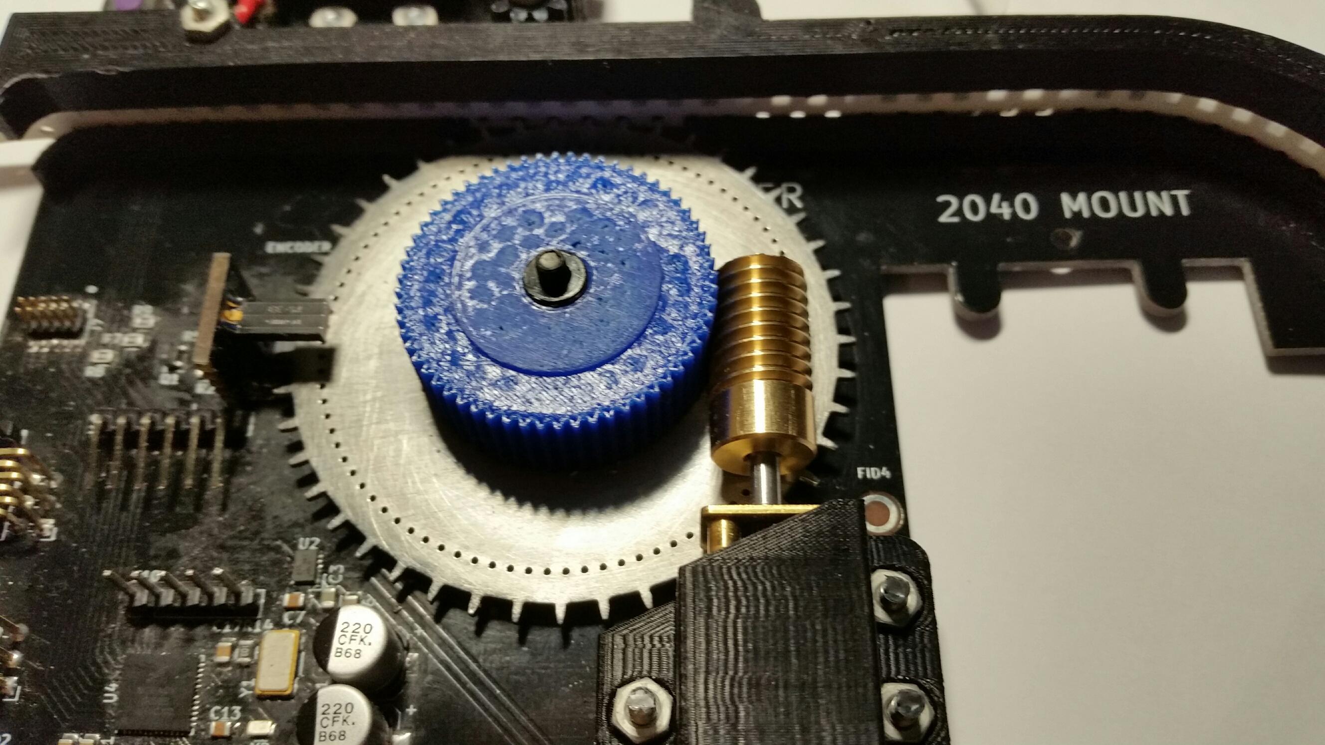
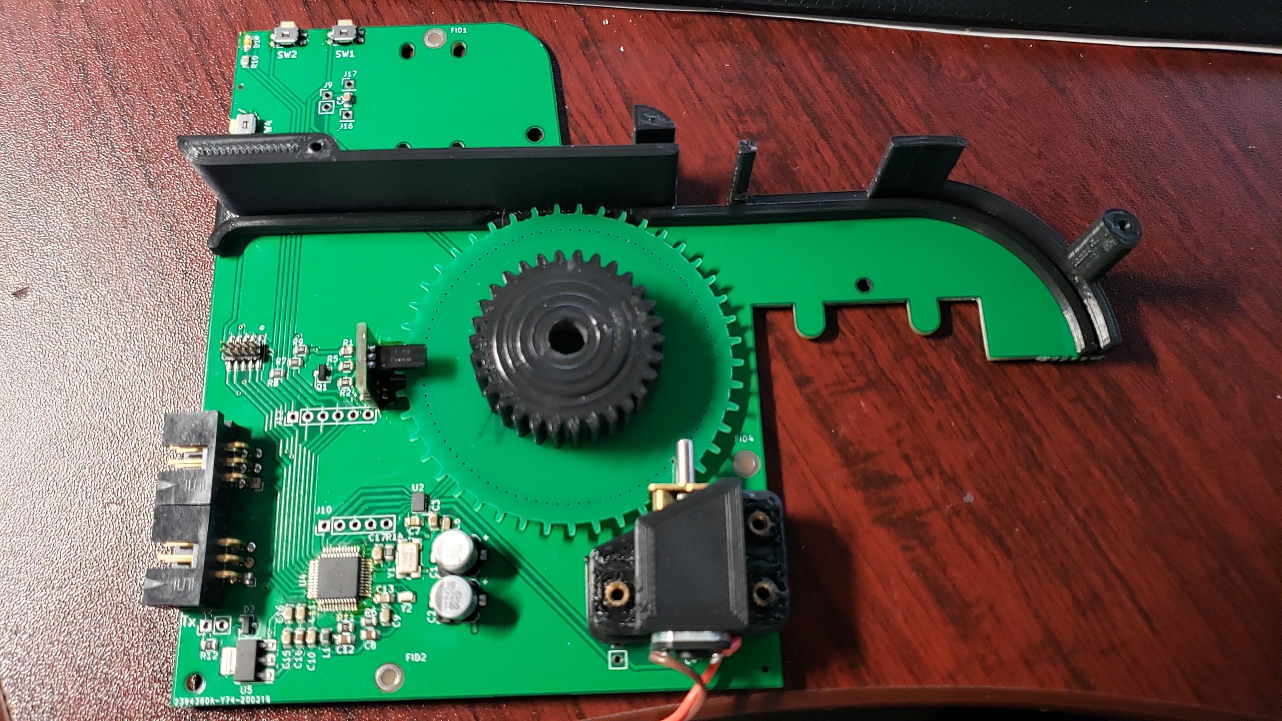
W dniu czwartek, 19 marca 2020 23:09:09 UTC+1 użytkownik Duncan Ellison napisał:
Sprockets now sorted :-)

I always thought this would be the hardest mechanical issue to resolve and I was right.  A combination of laser cut sprocket (polished) and a custom PLA 3D printed spur gear with dogs to engage on the sprocket and some epoxy resin glue.

20200319_215034_resized.jpg

20200319_214956_resized.jpg


Seems to feed quite nicely.

--
You received this message because you are subscribed to the Google Groups "OpenPnP" group.
To unsubscribe from this group and stop receiving emails from it, send an email to ope...@googlegroups.com.

Marek T.

unread,
Mar 20, 2020, 5:02:56 AM3/20/20
to OpenPnP
What is the thickness of this sprocket?

Duncan Ellison

unread,
Mar 20, 2020, 7:28:13 AM3/20/20
to OpenPnP
1mm stainless steel.

Marek T.

unread,
Mar 20, 2020, 8:46:19 AM3/20/20
to OpenPnP
I have cut something like this here in PL for £2 with good quality. But max thickness for this laser is 0.50mm.

Marius Liebenberg

unread,
Mar 20, 2020, 10:54:40 AM3/20/20
to OpenPnP
Jaume do you want to share your design with us?


On Friday, March 13, 2020 at 3:18:26 AM UTC+2, Jaume Olivé wrote:
Dear all,

I use a very simple design, derived from this project:


It's formed only by a 3d printed-body, a servo motor (converted to a DC motor driven by a H-bridge), a CAN-based control board, and a hole sensor (micro-switch or light sensor). No gears, no springs. The idea is to move the servo until a hole is detected.  


El jue., 12 mar. 2020 a las 19:52, Duncan Ellison (<duncan_...@colnewater.com>) escribió:
@John deGlavina

Ha!  So it looks like you are also too far down this rabbit hole to reverse out - LOL.

I actually thought this would be a nice test of the machine to build these as there's something nice about the machine assembling part of itself :-)  and it's a good test, if it can place these it can place anything.  So yes, I'm planning to populate all 40 boards.  I've got a proper stencil printer and a conveyor reflow oven, so that part it shouldn't be a challenge once I've got it dialled in.

I'm literally finishing up the translation of the documents myself, so if anyone else wants them in English -  I doubt that anyone will ever document the design of their feeders like this one (!).  

Good call on changing the board although I'm 2 out of 2 good placements on the TQFP48s so far.  They aren't actually so bad as the leads actually appear at the edge of the package and you can get a small iron in to touch up the solder if needed.  And I've already changed both H-Bridges with a hot air pencil as I placed them upside down (ooops).

To answer your other questions 

2) Any reason you 3d printed the sprocket instead of just ordering a 1mm PCB? 

Just to see if it was possible really and there's lead time involved in PCBs.  Also I did just order a couple from OSHPark last night and they work out a bit expensive.  Simon Huber just milled them from FR4 on the School's machine, but I don't have that luxury.

I'm aiming to actually get these laser cut as a batch with an additional two holes to act as a dog for the spur gear to key into.

I bought brass worm gears on Ali to replace the 3D printed ones, but could only get 0.5M pitch, so I'll need to make a custom 3D printed spur gear.


Let me know if you go down this route and I'll try to help you out with design files.
 

4) Different gears shouldn't matter, since the controller will stop the motor based on the sprocket position, right? 

I think so ....  but there will be a speed difference and there might be some timeout in the code, I'll need to look into that.  But I'm confident enough with the tools now that won't be an issue.


6) Yeah, it seems like most of everything is available. Where did you get the N20 motors? I actually have some on hand, but I'm pretty sure they are geared too low at 30rpm. I found new ones that look like they'll work at 100rpm, 6V

Ali.  https://pl.aliexpress.com/item/32770564311.html?spm=a2g0s.9042311.0.0.27425c0fxhcC7m    You are going to need 6V / 1:150 according to the documentation, I haven't got mine running yet uner processor control, but just powering them from a benchtop PSU, they seem about right. 

7) That's the only explanation! It's not much larger than an 0805 cap. 

If I didn't have the 40 boards and the ICs on hand, I'd seriously think of redesigning this.  It's not like you can't find DC motor drivers in more reasonably sized packages although for the first shot at this, I didn't want to have to deal with possible code chages as well.

8) Thanks! Luckily I got the right one. I noticed a few small changed between the versions

Good.  If I was doing this again (and I might if these work out), I'd re-work the push switches to be vertical, so they are easier to operate from the edge of the board.  I'd also sprinkle a few more LEDs around to make sure power supplies etc are good before closing up the board.

9) That is what I figured I would need to program them

If / When you get to this point, let me know, there's a bunch of things you need to get in the right order to set up the tool chain.  I assume that you'll just want to flash the boards and leave it at that?  I wanted to delve into the firmware so that I can adjust things as I go, so I needed a full compiling toolchain.

10) I was wondering about substituting that controller. Wouldn't you have to modify the code a lot to work with something 8 bit, Arduino based? 

No, I'm not planning to use the code, per se, just it's general functionality.  I plan to replicate this as an Arduino sketch or Python or something quick and dirty,  It only has to listen to USB commands and pass them on.  I haven't got into that yet, but I regard that as a minimal riask part of the project.


--
You received this message because you are subscribed to the Google Groups "OpenPnP" group.
To unsubscribe from this group and stop receiving emails from it, send an email to ope...@googlegroups.com.

fikret duru

unread,
Mar 20, 2020, 12:29:57 PM3/20/20
to ope...@googlegroups.com
can you send only gear file 

Marius Liebenberg <mdlca...@gmail.com>, 20 Mar 2020 Cum, 17:54 tarihinde şunu yazdı:
To unsubscribe from this group and stop receiving emails from it, send an email to openpnp+u...@googlegroups.com.
To view this discussion on the web visit https://groups.google.com/d/msgid/openpnp/60f13d32-e1fd-41c9-b7aa-5f56706a528e%40googlegroups.com.


--
XDSOFTr

Duncan Ellison

unread,
Mar 20, 2020, 5:28:26 PM3/20/20
to OpenPnP
@John,

Just to encourage you, I've just fed around 300 components without a problem and no loss in registration in the pick up window.

The holes in the sprocket seem to work just fine.

Duncan
  

Shai

unread,
Mar 20, 2020, 6:40:27 PM3/20/20
to OpenPnP
Duncan, what size are your holes and which sensor are you using again? Link?

Duncan Ellison

unread,
Mar 21, 2020, 5:45:20 AM3/21/20
to OpenPnP
Nominally 0.7mm.

Sensor is Omron EE-SX1350.   

The issue isn't really the size of the holes, it's the dark sectors.  This sensor has a detector window 0.5mm wide, so that needs to be completely covered, with no (Infra Red) light leakage so you can accurately detect a dark phase.

A level trigger circuit helps also.

Duncan   .  
encoder-ee_sx1350.pdf

Duncan Ellison

unread,
Mar 21, 2020, 6:18:14 AM3/21/20
to OpenPnP
For anyone who's interested, here's the output of the encoder after the level detector using the above sensor and the laser cut sprocket

NewFile1.png


Almost 50% duty cycle (53.27%) which I think is pretty close to optimal.

Duncan

John deGlavina

unread,
Mar 21, 2020, 10:04:20 AM3/21/20
to ope...@googlegroups.com
Wow, that's great! 

Did you have any trouble aligning the optical sensor with the sprocket?

--
You received this message because you are subscribed to a topic in the Google Groups "OpenPnP" group.
To unsubscribe from this topic, visit https://groups.google.com/d/topic/openpnp/2537gsOarBc/unsubscribe.
To unsubscribe from this group and all its topics, send an email to openpnp+u...@googlegroups.com.
To view this discussion on the web visit https://groups.google.com/d/msgid/openpnp/b6abfcfb-9a3d-4224-9b2b-5cc83ca71e50%40googlegroups.com.

Duncan Ellison

unread,
Mar 21, 2020, 10:32:50 AM3/21/20
to OpenPnP
No, there's a bit of wiggle room, but not much.

Assuming you didn't delete them :-0 - use the 'cross bar' mark on the PCB to align the slot part of the sensor and you should be good.

That assumes of course, that you didn't change the radius of the sensor holes appreciably.

Just putting another batch of 3 through the machine now.  will let you know how I get on.

Duncan


On Saturday, 21 March 2020 14:04:20 UTC, John deGlavina wrote:
Wow, that's great! 

Did you have any trouble aligning the optical sensor with the sprocket?

On Fri, Mar 20, 2020, 5:28 PM Duncan Ellison <duncan_...@colnewater.com> wrote:
@John,

Just to encourage you, I've just fed around 300 components without a problem and no loss in registration in the pick up window.

The holes in the sprocket seem to work just fine.

Duncan
  

--
You received this message because you are subscribed to a topic in the Google Groups "OpenPnP" group.
To unsubscribe from this topic, visit https://groups.google.com/d/topic/openpnp/2537gsOarBc/unsubscribe.
To unsubscribe from this group and all its topics, send an email to ope...@googlegroups.com.

Simon Gerber

unread,
Mar 21, 2020, 10:33:19 AM3/21/20
to OpenPnP

Hello guys


Happy to find an active discussion on pnp feeders!


I am thinking of building an openpnp machine for myself… However I have not found a cheap automatic feeder that meets my requirements. I don’t like the solutions with hobby servos or asymmetrical and different shapes due to motor placement... But this automatic feeder from Scavenger18 seems pretty close to what I’m looking for, even though it is pretty large. ;-)


Most of you seem to have already built what they need. However, would someone be interested in an automatic feeder with the following features?

- Integrated microcontroller (probably stm32 based)

- USB connection for configuration (chip type, quantity, footprint, feeder dimension, etc.)

- Pluggable on a magnetic, power/communication rail

- Automatic slot recognition (with all infos stored on feeder)

- Smaller dimensions

- One motor solution (not 100% sure if this will cause more problems than it solves...)


unfortunately i have to warn you that i have to finish another project at the moment, so i will probably not be able to start with the PNP machine or the feeder before the end of summer.


Best regards

Simon


Am Donnerstag, 12. März 2020 13:47:42 UTC+1 schrieb John deGlavina:
I've been looking for a more robust feeder solution for a while now, and I forgot about this one, which I originally saw on the McuOnEclipse OpenPNP machine. 


These will be able to do exactly what I want. However they're programmed on a platform that I'm not familiar with. The 32bit NXP K20's and K22's. It looks like the software here is slightly more up to date


Does anyone have experience with these feeders and/or controller (tinyK20)? 


Duncan Ellison

unread,
Mar 21, 2020, 10:44:12 AM3/21/20
to OpenPnP
Hello Simon and welcome this rather long thread :-)

I think we'd all be interested in that.  

But be careful what you wish for, just replicating this design has been a very time consuming (and not inexpensive) process for me at least.

The upside is I learned a lot about things I've not had to deal with before and even if I ditch these feeders eventually, it's still been a very worthwhile learning exercise.  Which (I think) is why most of us are here - otherwise we'd all save up and buy cheap Chinese machines ;-)

Duncan 

Jarosław Karwik

unread,
Mar 21, 2020, 12:02:20 PM3/21/20
to OpenPnP
If you want fater result with feeders - you can get  quite reasonable mechanical feeders - used ones, but with plenty of life ( I would say forever unless you are professional manufactururer).
I bought DIMA feeders for ~ 20Euro / pcs  and Philips feeders for 9Euro / pcs ( contact me PM if you want such feeders).
Then you only need to prepare your machine head to perform simple push ( by the head or separate actuator or motor  - there are plenty ways)

Rememeber - feeders are more complicated then the machine itself.

Balázs buglyó

unread,
Mar 21, 2020, 12:15:57 PM3/21/20
to ope...@googlegroups.com
What kind of Philiphs feeder ?? :)


--
You received this message because you are subscribed to the Google Groups "OpenPnP" group.
To unsubscribe from this group and stop receiving emails from it, send an email to openpnp+u...@googlegroups.com.
To view this discussion on the web visit https://groups.google.com/d/msgid/openpnp/f64b8e71-06bd-4578-820a-9768485da31a%40googlegroups.com.

Jarosław Karwik

unread,
Mar 21, 2020, 12:23:14 PM3/21/20
to OpenPnP
Something like this - I can make pictures on Monday if you are interested ( I have 40x 8mm federes and 5x 12mm ) - possibly for sale , even with assembly plates

ph_feeder.jpg

To unsubscribe from this group and stop receiving emails from it, send an email to ope...@googlegroups.com.

John deGlavina

unread,
Mar 26, 2020, 3:52:55 PM3/26/20
to OpenPnP


I just got the pcbs a couple days ago, and got some pieces together. The actually did the optical sensor by solding it to the main board first, the the small piece. 


also managed to get the firmware flashed to the feeder. I havent hooked up anything else yet to make sure they actually work though. Is the LED supposed to turn on with power?

20200326_075438.jpg

Shai

unread,
Mar 26, 2020, 4:40:25 PM3/26/20
to OpenPnP
Hi John,

For your sprocket, are the inside edges sharp? Because I did that once and noticed the factory wasn't able to cut the edges sharp and as a result the tape wouldn't sit well if you tried it with embossed plastic tape especially. I had to modify the design to do it like this:

screenshot_212.png

Duncan Ellison

unread,
Mar 26, 2020, 5:27:07 PM3/26/20
to OpenPnP
Hi John,

This thread is getting a bit ragged now.  The other guys seem to be using it as a discussion space for all kinds of stuff.  

I'll reply to you on a new thread,  Watch out for 'Simon's Feeder'. 

Kent Kim

unread,
Mar 26, 2020, 5:27:15 PM3/26/20
to OpenPnP
Hi Jaume,

I was on the site and did not see the print/build files specifically for the feeder interested to test this out.  Did you just design completely? Was not sure if your design was available for download.  Hope you are safe in these challenging times.
--
You received this message because you are subscribed to the Google Groups "OpenPnP" group.
To unsubscribe from this group and stop receiving emails from it, send an email to ope...@googlegroups.com.
To view this discussion on the web visit https://groups.google.com/d/msgid/openpnp/0fcb5cc2-0b3c-494e-8c5d-acf0e6b7fc0f%40googlegroups.com.

Michael Anton

unread,
Mar 26, 2020, 5:28:55 PM3/26/20
to OpenPnP
You should plan on having inside corners radiused by at least 0.5mm, and probably more like 1mm, as I think a 2mm router bit is commonly used.  You should ask the fab you are using to confirm this though.

John deGlavina

unread,
Mar 27, 2020, 12:38:30 PM3/27/20
to ope...@googlegroups.com
Hi Shai,

The edges look pretty flat and sharp. I still have to get everything assembled properly, but so far they seems to be working.


--
You received this message because you are subscribed to a topic in the Google Groups "OpenPnP" group.
To unsubscribe from this topic, visit https://groups.google.com/d/topic/openpnp/2537gsOarBc/unsubscribe.
To unsubscribe from this group and all its topics, send an email to openpnp+u...@googlegroups.com.
To view this discussion on the web visit https://groups.google.com/d/msgid/openpnp/d2c8524c-3ec7-428e-8392-4f0c092a063c%40googlegroups.com.
Reply all
Reply to author
Forward
0 new messages