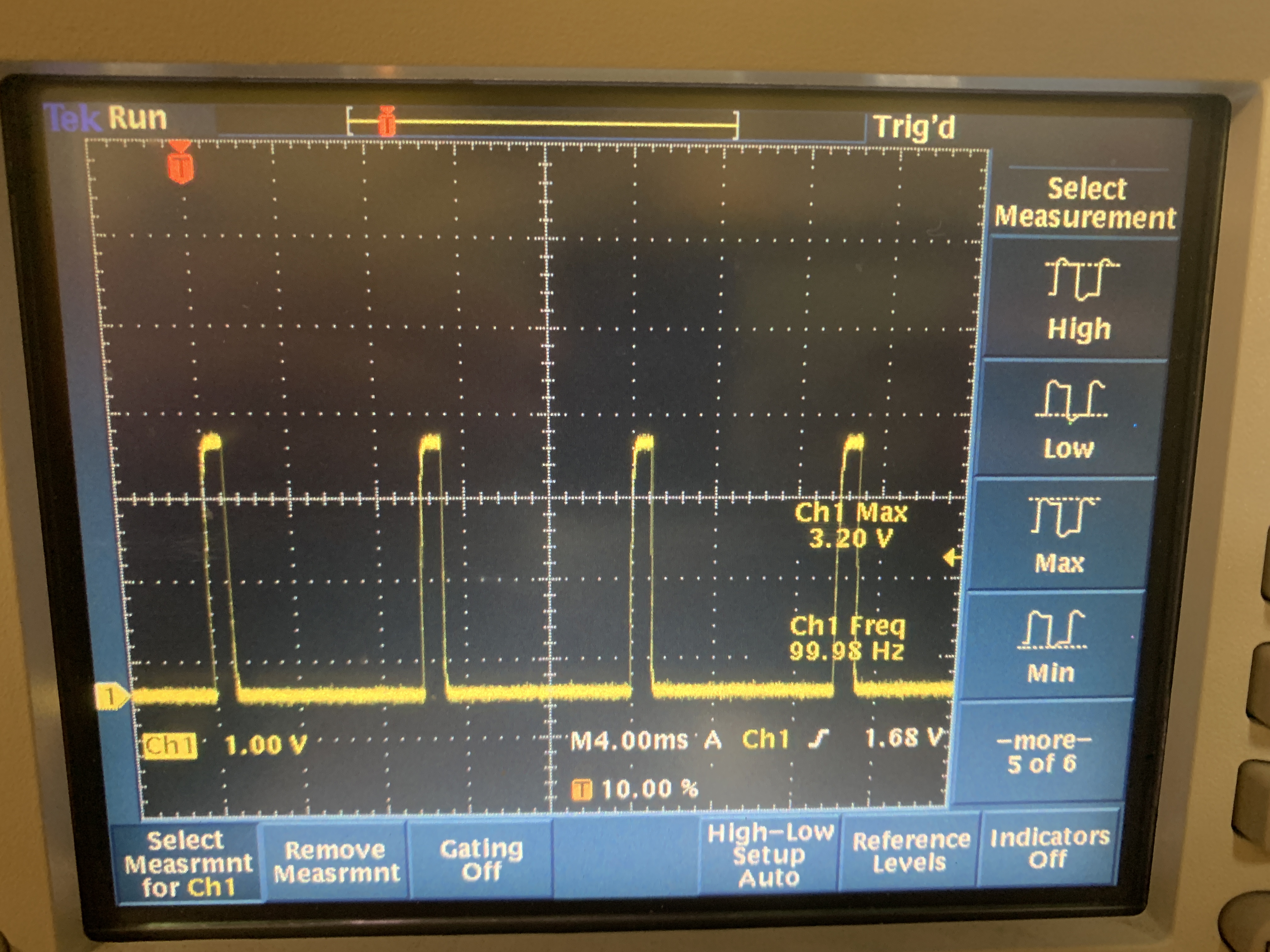
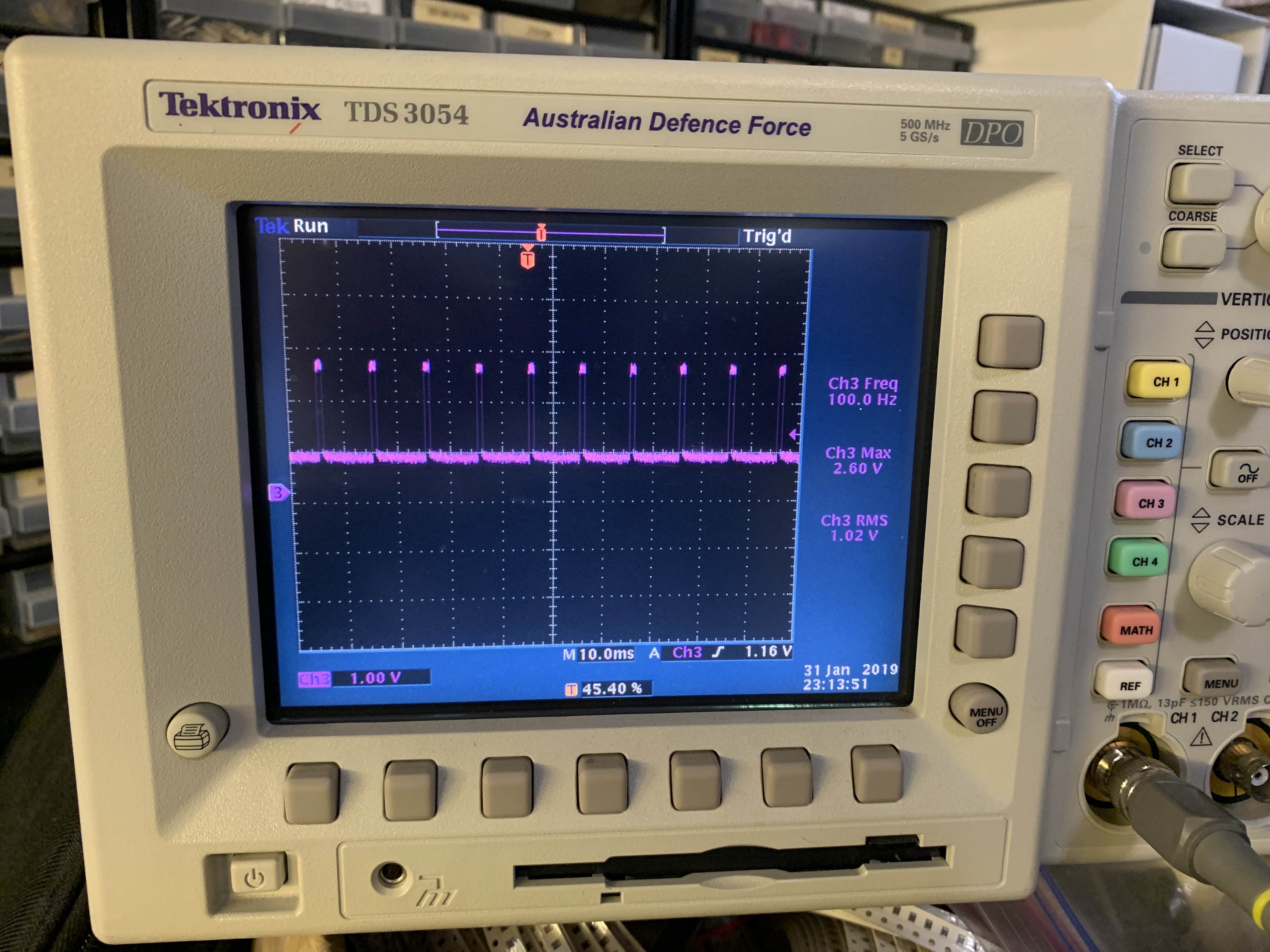
100Hz pulse on SS2 Vacuum TinyG firmware?

Roman Valls

mark maker
Hi Roman,
You're probably the first that really tests this. @Michael Schober said he would test it here...
https://groups.google.com/g/openpnp/c/SpnIfjEoiuI/m/LMgSRJ3uAQAJ
... but if I'm not mistaken, he never actually reported back. I'm
frankly not even sure if I tested it electronically myself. It is
well possible that I made a mistake in the setup, I really just
took the code of Thereza.
At the time I was assuming Micheal would test it immediately.
Then I probably just assumed I would hear back if it didn't work.
Unfortunately, that TinyG ADC discussion thread then got
completely hijacked after that.
Having said that...
> I insist, without anything else connected
Leaving the SS2 pin open will likely give random ADC reads. The
100Hz could easily be a harmonic interference from the 50Hz mains,
and if you probed it with long oscilloscope with multimegaohm
impedance, this is even very likely.
Do you have a potentiometer (10 kOhm or similar) that you could
connect across the 3.3V and then go from the tap to SS2?
You should also connect a cap in parallel, as I documented.
             ______
+3.3V o-----[______]---o GND
           10k ^       |
               |   1uF |
               o---||--o
               |
              SS2
Please stay on it! 😁
_Mark
--
You received this message because you are subscribed to the Google Groups "OpenPnP" group.
To unsubscribe from this group and stop receiving emails from it, send an email to openpnp+u...@googlegroups.com.
To view this discussion on the web visit https://groups.google.com/d/msgid/openpnp/b8e69cf7-e68e-4a0d-a711-e219ba37eadfn%40googlegroups.com.
Roman Valls
photo, but it's there from the beginning, as documented by you ;)
I'll try the 10k resistor and/or pot next Tuesday... if you can think
of any other reason, please do tell in advance since I'm there only
once a week. We revised your TinyG code and the adc_init() & co and it
seems sound, btw... but perhaps there's something somewhere else on
the firmware that could be generating that 100Hz PWM-looking-like
pulse?
> To unsubscribe from this topic, visit https://groups.google.com/d/topic/openpnp/0tcJh1ygayk/unsubscribe.
> To unsubscribe from this group and all its topics, send an email to openpnp+u...@googlegroups.com.
> To view this discussion on the web visit https://groups.google.com/d/msgid/openpnp/1a8aced1-f559-32d7-1301-82b6fe35fb96%40makr.zone.
mark maker
> but perhaps there's something somewhere else on the
firmware that could be generating that 100Hz PWM-looking-like pulse?
Hmmm... naturally, the SS1 pin would normally be a SPI select
line, perhaps I should have done something to relinquish SPI
control? Though I always thought these are just plain software
controlled IOs on these old 8bit MCUs, i.e. not actually
controlled by some built-in SPI hardware.
The only other thing that I can think of, is that I made a mistake when building the later firmware, i.e. the one that also solves the "spindle control plus Z-probe" issue that must be solved for the Liteplacer. Look for "UPDATE 2022-04-24" here:
https://makr.zone/tinyg-new-g-code-commands-for-openpnp-use/577/
Perhaps I zipped the wrong hex? Although the date seems right. The hex is baked right into the corresponding code changes, including ADC (I checked):
https://github.com/synthetos/TinyG/pull/276
To be sure, please try this hex:
I have the quirky AVR build environment on my old computer, i.e.
can't just spin a new version readily...
Any chance you could do that yourself? If would enable you to
actually experiment with the code, if you're only there once in a
week:
https://github.com/synthetos/TinyG/wiki/Project-Setup-For-Atmel-Studio6.2

Ian Arkver
Ian
mark maker
Its a bit embarrassing, but I really just took the code
from Thereza (seems to be deleted now), which reportedly
worked. To be honest: while it all made sense, I did not really
know what I was doing in terms of all the Atmega specifics.
The code was a bit cleaned up, taking only what is needed from
the ATmega SDK, and controlled with different G-code. But unless I
made a mistake, all the original stuff should be there. I was very
careful then.
_Mark
To view this discussion on the web visit https://groups.google.com/d/msgid/openpnp/1c29ac89-90cf-4033-838f-a06bb7d2f53an%40googlegroups.com.
Ian Arkver
But I can't really be sure it will help and I can't test it.
Ian
mark maker
Thanks for your help, Ian, that seems a valid suspicion.
Like I said I cannot currently look into that, maybe Roman can.
But I will keep it in the back of my mind.
_Mark
To view this discussion on the web visit https://groups.google.com/d/msgid/openpnp/41d351bb-0478-4190-bf84-483c7e72ef06n%40googlegroups.com.
Roman Valls
mark maker
Is that on a real oscilloscope? (i.e. not just one of these "signal monitors")
Is it a strong rectangular signal, definitely driven by the MCU? Or could it be interference?
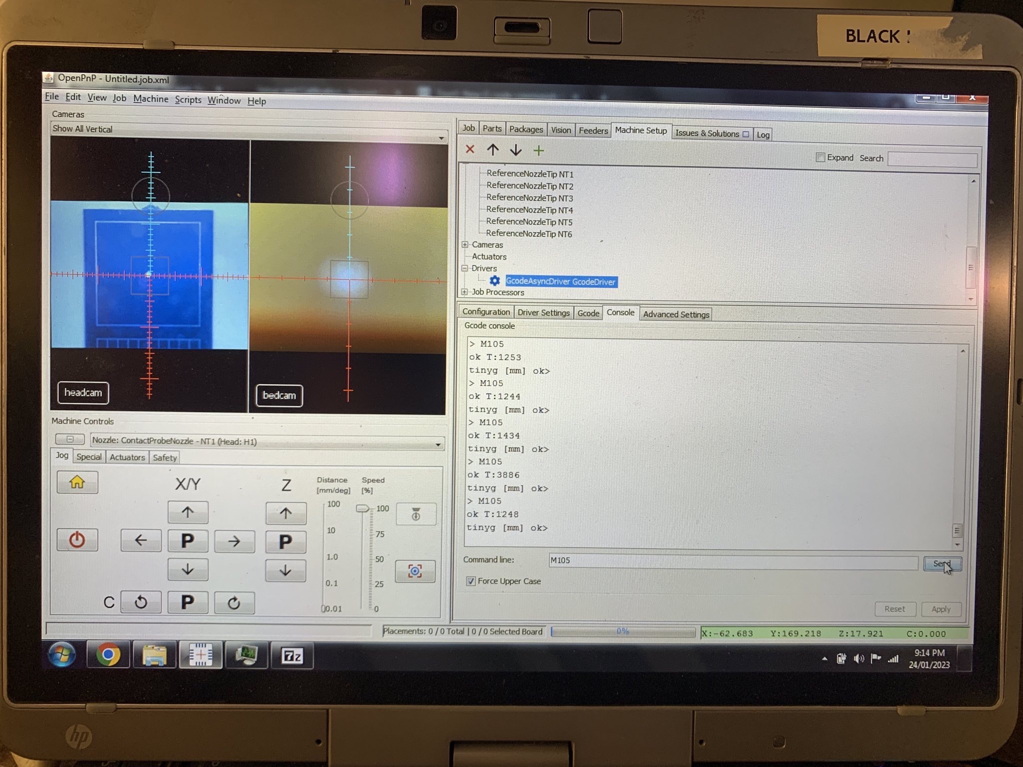
Have you ever just tied the SS2 to GND and +3V3 respectively, using a 10k resistor, and then used M105 to see if you can see the difference?
> @Mark: If I'm the first trying this vacuum sensing method, what are you using yourself for your LitePlacer machine nowadays? :-S
I replaced the controller:
https://makr.zone/choosing-a-motion-controller-the-panucatt-azteeg-x5-gt-32bit/455/
Using this for sensing:
https://makr.zone/vacuum-sensor/192/
But that was at a time when OpenPnP still strongly advised
against using the TinyG. But a lot of Liteplacer users still kept
using it, then hit the obvious problems when they wanted to do
advanced stuff, so I finally added the missing G-code commands:
https://makr.zone/tinyg-new-g-code-commands-for-openpnp-use/577/
_Mark
To view this discussion on the web visit https://groups.google.com/d/msgid/openpnp/3d9753c8-3954-4691-ba7c-307fae89bf5cn%40googlegroups.com.
mark maker
> Have you ever just tied the SS2 to GND and +3V3 respectively, using a 10k resistor, and then used M105 to see if you can see the difference?
Now that I wrote that down, a recollection manifests, that I actually did that when I developed the ADC addition. I'm not 100% positive whether I did it or just thought about it. Actually, the image in my head is about recklessly used a paperclip to short SS2 to GND and +3V3 respectively (my controller test bed is actually in my office, no electronic tools or parts laying around 😁).
A transformer PSU uses a rectifier, which creates a 100Hz
half-waves signal with typical capacitor inrush pulses:
https://electronics.stackexchange.com/a/441961
If it is a phase cutting PSU, it is the same issue:
https://en.wikipedia.org/wiki/Phase-fired_controller
If you leave the SS2 port floating, and attach the high impedance
(typically 10MOhm) leads of the scope to it, it is almost
guaranteed to pick those 100Hz up.
In my shop I had fluorescent tube overhead lights, they were all over my scope signals. I had to replace them with LEDs. Still a lot of noise there. You really have to tie any signal down with 100k or less.
Having said all that: remember, I'm just a hobbyist. What do I know... 😉
_Mark
To view this discussion on the web visit https://groups.google.com/d/msgid/openpnp/307edba8-39ba-3266-269f-06c47c24ade1%40makr.zone.
Ian Arkver
Ian
Roman Valls
Ian Arkver
Ian
mark maker
>OP (Roman?) showed a pic of the scope trace in the first post
Duh, missed that ...
To view this discussion on the web visit https://groups.google.com/d/msgid/openpnp/a2e1bedf-6c41-4756-8766-e6a00c891842n%40googlegroups.com.
mark maker
Cool!
But how does this make sense? Who would setup SPI chip select and a PWM on the same line? And what for?
_Mark
To view this discussion on the web visit https://groups.google.com/d/msgid/openpnp/aaf43586-41a4-48c8-ad6d-a8c0c1d00259n%40googlegroups.com.
mark maker
Anyways, I will integrate it as soon as I get that old AVR IDE
setup running again...
To view this discussion on the web visit https://groups.google.com/d/msgid/openpnp/06f7d6a0-2878-4d34-a51a-262a62a91f79%40makr.zone.
Ian Arkver
IanJ
mark
On 7 Feb 2023, at 12:06, Ian Arkver <ian.ark...@gmail.com> wrote:
To view this discussion on the web visit https://groups.google.com/d/msgid/openpnp/3db23abf-1001-48fe-90df-02bb2656c1b8n%40googlegroups.com.
Roman Valls
mark
To view this discussion on the web visit https://groups.google.com/d/msgid/openpnp/751091b5-d9dd-4cca-92bc-da724afd7f0en%40googlegroups.com.
Roman Valls
Ian Arkver
Roman Valls
mark maker
> Mark, do you want me to cherry pick Roman's one favoured commit into my branch, which is now more of a mop-up branch? Or would you prefer separate PRs?
After having a closer look, I believe the change is not really a fix after all, it just removes the $p1frq setting from the EEPROM settings. 🤔
I guess one could likely just use the command
$p1frq=0
to disable the PWM output. That would also explain, why other
users (including me) were able to use the ADC. See also here:
Removing the p1frq register also changes the layout of the EEPROM, which means users would corrupt their settings on updating to our new firmware. 😨
Furthermore, I'm not sure the pwm.c[PWM_1].frequency
data field would be properly initialized (to zero), if it were no
longer controlled by the p1frq setting.
It could then well contain random garbage, so it would
intermittently work when the garbage is outside frequency range as
checked by pwm_set_freq(), and then
sometimes not. See here:
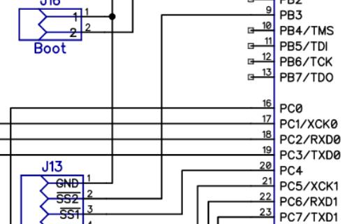
I guess the actual bug is that the inner PWM source is currently mapped to the SS2 output pin for some reason. It would be cool to fix that instead of just disabling PWM altogether. The SS2 is not on the schematic, unfortunately. PWM is on PD5.
I have no idea how that pin mapping stuff works on an AVR, so I hope I can leave it to you, seeing you have a lot of experience with that avr-gcc stuff 😁
_Mark
To view this discussion on the web visit https://groups.google.com/d/msgid/openpnp/7e220cd1-bc96-4bd6-97bf-96c1abac6f1an%40googlegroups.com.
Ian Arkver
IanJ
Ian Arkver
Ian

Philip Kristoffersen
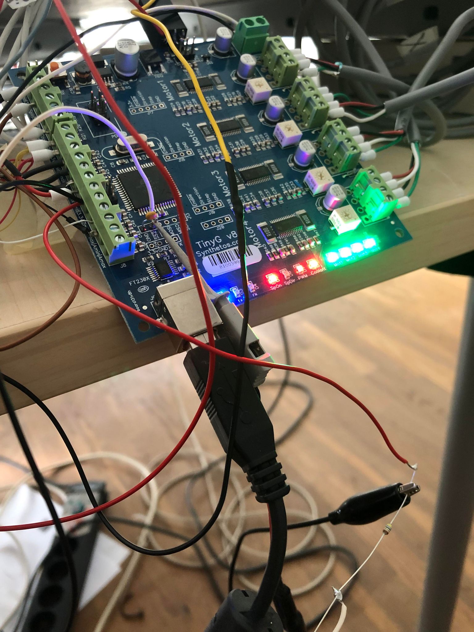
Just adding my stuff for comparison,
Setup of the Oscolioscope:
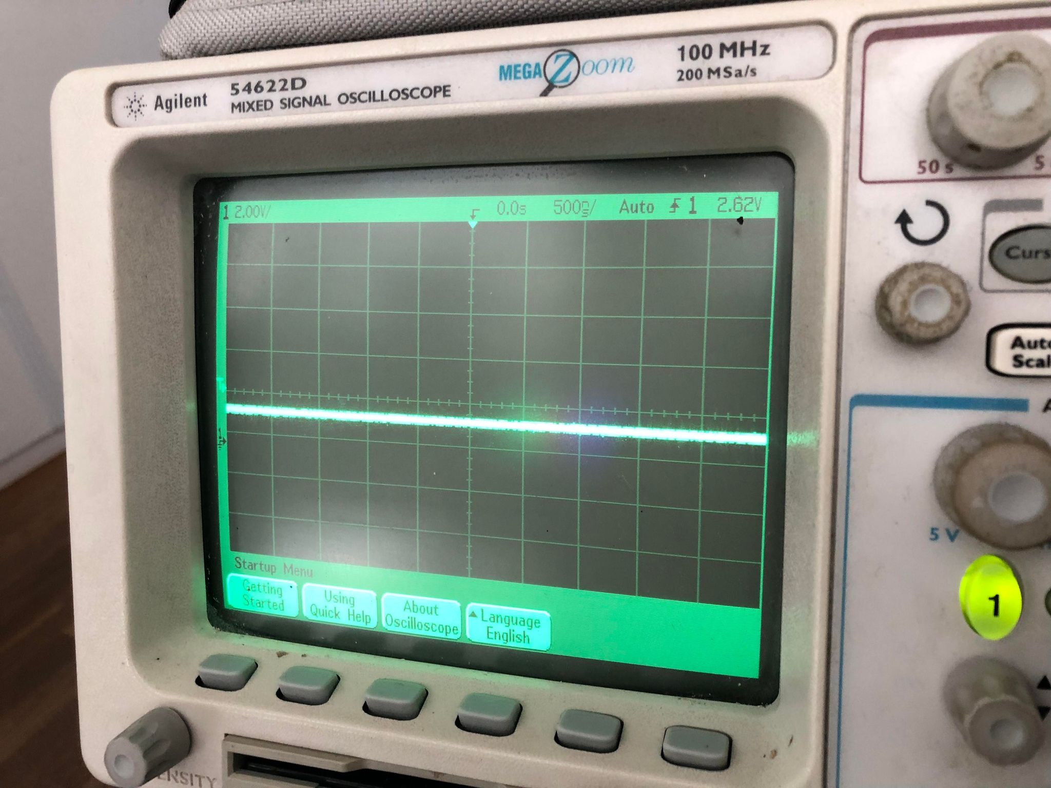
Measurement pump ON:
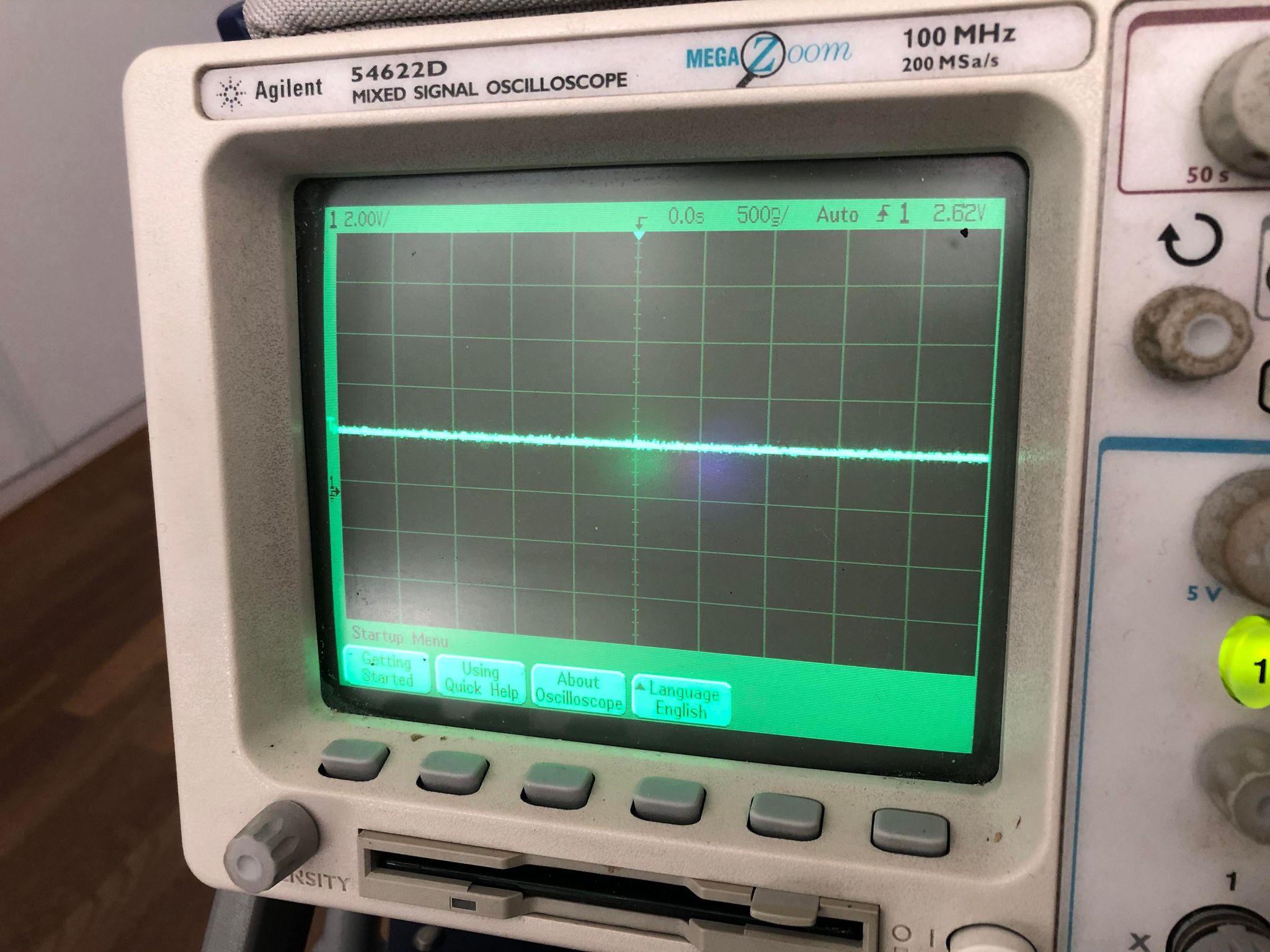
Measurement pump OFF:
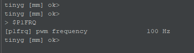
PWM Hz Settings:
My signal is stable, I watched it for a good few minutes and there is no deviation from what would be expected - I am not seeing anything that mimics a PWM signal or spikes to the same voltage range.
My TinyG V8 was first flashed with the official 420.20 firmware from TinyG, afterwards I flashed the 420.21 firmware onto the TinyG and then I have configured TinyG settings from there, but I have not touched anything other than motor settings.
- Philip
mark maker
> Re: SS2 on the schematic - I think it is (on PB3), though it's maybe not a named net...
I must have been blind.😅
> I think ensuring that no digital function is driving the output, and no digital input is reading it, should allow it to work as an analog input, but without a board to try it on I'm guessing.
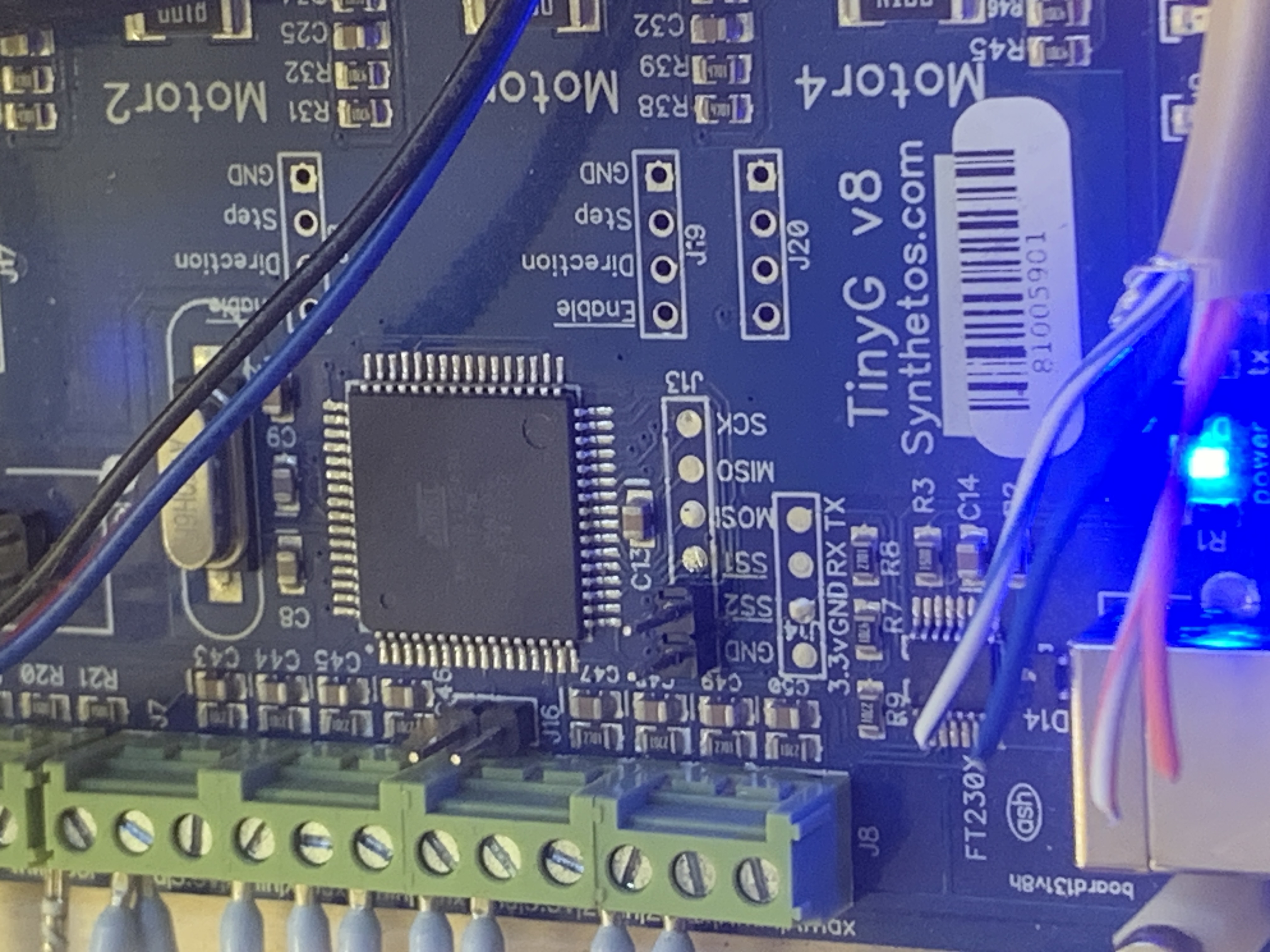
I have a board, but no clue where to look for outputs mapping. I
found this...
https://www.electroschematics.com/avr-pwm/
.. but no OCR1A in the TinyG source.
_Mark
To view this discussion on the web visit https://groups.google.com/d/msgid/openpnp/aea53295-61e9-4f98-96a4-3026288ab42en%40googlegroups.com.
Roman Valls
To view this discussion on the web visit https://groups.google.com/d/msgid/openpnp/555a275c-87d3-677e-5975-66f7fcee406d%40makr.zone.
Ian Arkver
Ian
Roman Valls
Ian Arkver
Ian
markmaker
Yes and be sure to use the right syntax afaik it is case sensitive and you need the = to assign.
_mark
markmaker
Roman Valls
mark maker
> 1.1) Funny side effect of typing P1FRQ command with the "wrong" syntax on the console: the whole OpenPnP java app locks up :shrug:.
Yep, the console is very simple. Until it receives an "ok" it
will simply hang, only to be relieved by the timeout.
> The 100Hz seems to be a stray EEPROM setting, that I couldn't switch to 0 regardless of the correct syntax of the command (thanks Mark).
Maybe it was another option, or maybe multiple options have the effect of enabling the PWM. Do you still have the $$ dump?
Whatever it is: I guess the PWM pin mapping is faulty, i.e. even with PWM enabled the ADC should still work. And unless someone with AVR knowledge comes along, I guess we're stuck.
I haven't forgotten forget Ian's fork,
just no time to test on the board anytime soon (this will likely
be more than a 10 minute endeavor).
_Mark
--
You received this message because you are subscribed to the Google Groups "OpenPnP" group.
To unsubscribe from this group and stop receiving emails from it, send an email to openpnp+u...@googlegroups.com.
To view this discussion on the web visit https://groups.google.com/d/msgid/openpnp/4d5b2f66-7805-4767-8495-02cd4181763fn%40googlegroups.com.
Roman Valls
> 1.1) Funny side effect of typing P1FRQ command with the "wrong" syntax on the console: the whole OpenPnP java app locks up :shrug:.
Yep, the console is very simple. Until it receives an "ok" it will simply hang, only to be relieved by the timeout.
> The 100Hz seems to be a stray EEPROM setting, that I couldn't switch to 0 regardless of the correct syntax of the command (thanks Mark).
Maybe it was another option, or maybe multiple options have the effect of enabling the PWM. Do you still have the $$ dump?
Whatever it is: I guess the PWM pin mapping is faulty, i.e. even with PWM enabled the ADC should still work. And unless someone with AVR knowledge comes along, I guess we're stuck.
I haven't forgotten forget Ian's fork, just no time to test on the board anytime soon (this will likely be more than a 10 minute endeavor).
You received this message because you are subscribed to a topic in the Google Groups "OpenPnP" group.
To unsubscribe from this topic, visit https://groups.google.com/d/topic/openpnp/0tcJh1ygayk/unsubscribe.
To unsubscribe from this group and all its topics, send an email to openpnp+u...@googlegroups.com.
To view this discussion on the web visit https://groups.google.com/d/msgid/openpnp/828b68df-209a-2340-ca7c-ca5169479740%40makr.zone.
mark maker
> Sure, but is it really necessary to lock the whole UI? I'd expect the UI to be running on a separate thread and not lock up?
I guess it is veery old code.
This is just written as blocking ping pong, i.e. only after it sent a command, it expects at least one response and then sends it to the console output. You would have to rewrite it from scratch to constantly monitor responses and just put them into the console whenever (and if ever) they arrive. I.e. add a listener interface on responses in the driver. And it would probably have to carefully add/remove itself as a listener to only be active when the Console tab is on top. Otherwise it would put a performance penalty on the whole driver comms.
_Mark
To view this discussion on the web visit https://groups.google.com/d/msgid/openpnp/CAOpFiqs91khr%3D-QmfKHqCqqtvAB4avKHFnfRxyjZMkjy4fMSgA%40mail.gmail.com.