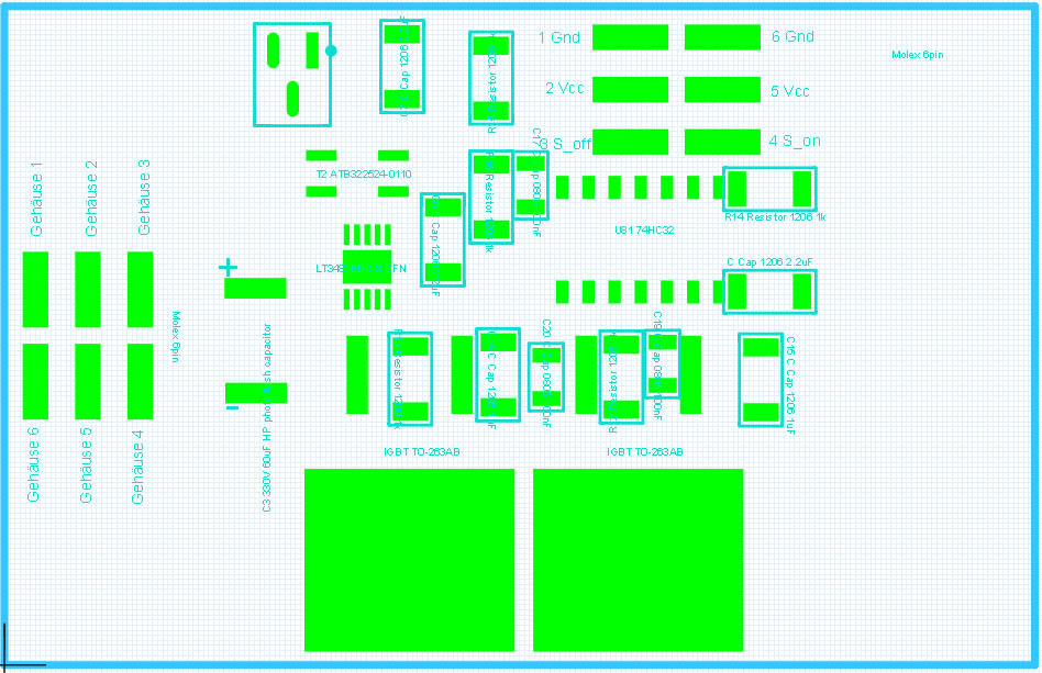
EPM Example Circuit

74 views
Skip to first unread message

Miles Smith

unread,
Aug 1, 2013, 8:18:35 PM8/1/13
to open...@googlegroups.com
Hey everyone,

I finally got my EPM, however I'm having a hard time figuring out how it's supposed to be hooked up. I put 5v on the Vcc pin, and ground to the ground pin. I have S_On hooked up to a DPDT switch, one throw to GND the other to 5v. When I cycle it to 5v (HIGH) for 3s, and then back down, I get no response. I'm not sure if this is the proper way to hook it up, if not could someone shed some light on it?

-- 
Miles 'wedtm' Smith

Kevyn Watkins

unread,
Aug 1, 2013, 8:53:46 PM8/1/13
to open...@googlegroups.com
I've had trouble with this also. I've got it on a breadboard with power and gnd hooked up as 5v and gnd, reading the instructions:

S_off (Pin 3)

Pulling this pin high (1 kohm pull down) causes the magnet to go in the off state if the capacitor is charged, the discharge will automatically stop in 300uS even if kept high. Holding this pin high for 3s charges the capacitor to full and is ready for the next cycle. The relative high self discharge rate of the capacitor should be taken into account, recommended time is <10s.


I am a little confused, do I put a 1k resistor between pin 3 and ground (pull down) and a switch to 5v? if so do I hold the switch on for 3s, then click it for 0.5s? Doing this has had no response, sitting it next to my phone with a magnetometer app running to measure the flux field strength.

I have tried with and without the pull down, pull up, short to ground, short to 5v. I'm really not sure what I've done wrong. I haven't been able to measure any voltage out of the large cap at any stage.


-- 
Miles 'wedtm' Smith

--
You received this message because you are subscribed to the Google Groups "OpenGrab" group.
To unsubscribe from this group and stop receiving emails from it, send an email to opengrab+u...@googlegroups.com.
To post to this group, send email to open...@googlegroups.com.
For more options, visit https://groups.google.com/groups/opt_out.


ctech

unread,
Aug 1, 2013, 8:54:28 PM8/1/13
to open...@googlegroups.com
Pin 3 and Pin 4 have a 1kohm pull down so you can leave them floating when not using

Connect Pin2 or Pin 5 or both to 5V
Connect Pin1 or Pin 6 or both to GND

Connect Pin3 and Pin4 separately to two switches

when you want to switch you have to first charge the capacitor and you do that by holding Pin3 or Pin4 high for 3s
now your ready to switch
Pull Pin3 or Pin4 high to either turn it on or off
keep the pin pulled high for 3s if you want to charge the capacitor up again

(Miles you have version 1.2x so this does not concern you)
If you have version 1.0x i recommend strapping a capacitor between your switch pin and ground, 100nF-1000uF will do, because some switches make a lot of noise, eg they don't switch clean which can cause problems for that version

jeff: wanna write this up for the wiki.....


-- 
Miles 'wedtm' Smith

ctech

unread,
Aug 1, 2013, 8:57:58 PM8/1/13
to open...@googlegroups.com
fixed the wording from "(1 kohm pull down)" to "(it has a 1 kohm pull down)"

>I have tried with and without the pull down, pull up, short to ground, short to 5v. I'm really not sure what I've done wrong. I haven't been able to measure any voltage out of the large cap at any stage.
if you have done this:

ctech

unread,
Aug 1, 2013, 9:00:55 PM8/1/13
to open...@googlegroups.com
oops hit the send button to quickly..


>I have tried with and without the pull down, pull up, short to ground, short to 5v. I'm really not sure what I've done wrong. I haven't been able to measure any voltage out of the large cap at any stage.
if you have done this:

Connect Pin2 or Pin 5 or both to 5V
Connect Pin1 or Pin 6 or both to GND
and pulled Pin3 or Pin4 to 5V you should measure the capacitor voltage change, if you don't chat me up at ctech4285 at gmail dot com to make sure that your unit is not faulty


Miles Smith

unread,
Aug 1, 2013, 9:39:12 PM8/1/13
to open...@googlegroups.com
Kevyn,

I figured my issue out. What you need to do is supply ANY of the 2 GND pins with GND, ANY of the two 5v pins with 5v, and you need to wire a switch to EACH S_Off, and S_On. The switch should pull the pins to 5v when activated.

To activate the magnet, simply hold down ANY button for 3 seconds. Then push the button that corresponds with the action you want to take (S_On to turn it on, S_Off to turn it off). That should activate the magnet.

Hope this helps!

-- 
Miles 'wedtm' Smith

Kevyn Watkins

unread,
Aug 2, 2013, 2:52:49 AM8/2/13
to open...@googlegroups.com
So is this wiring diagram correct/ If so i think I have a dead board :-( i can arrange to send it back to you.
EPM Wiring_bb.jpg

ctech

unread,
Aug 2, 2013, 11:06:33 AM8/2/13
to open...@googlegroups.com
i can't spot anything obviously wrong
can you confirm that you have ~5V between the one of the center pins and one of the outer pins?
and that when you activate the switches that the respected pin go to 5V?


yeab if it's dead we'll send you an other one


Miles Smith

unread,
Aug 2, 2013, 2:53:01 PM8/2/13
to open...@googlegroups.com
Kevyn, I'm not sure your 7805 is getting power. Most of the time, bread boards do not connect across the center gap. Try moving the 7805 to the E row.

-- 
Miles 'wedtm' Smith

ctech

unread,
Aug 2, 2013, 4:58:13 PM8/2/13
to open...@googlegroups.com
ha your right Miles, just checked it on a bread board
good find!

Miles Smith

unread,
Aug 2, 2013, 5:00:29 PM8/2/13
to open...@googlegroups.com
No problem! Glad to help!

-- 
Miles 'wedtm' Smith

Kevyn Watkins

unread,
Aug 2, 2013, 5:57:00 PM8/2/13
to open...@googlegroups.com

Fritzing mighty make it obvious, but there are wire bridges across the center. And a multimeter confirms the pin is going high.

Kevyn Watkins

unread,
Aug 2, 2013, 6:22:20 PM8/2/13
to open...@googlegroups.com
Updated image in case others are looking for how to wire this up. The important part is obviously the right hand side.
EPM Wiring_bb.jpg

ctech

unread,
Aug 2, 2013, 7:51:21 PM8/2/13
to open...@googlegroups.com
looks correct,
so if you have the wires connected up like in the picture:
Inline image 1


and you checked the levels with a volt meter then your unit is defective


Reply all
Reply to author
Forward
0 new messages