OpenEVSE II

624 views
Skip to first unread message

Nicholas Sayer

unread,
Jun 8, 2014, 4:23:40 PM6/8/14
to open...@googlegroups.com
I sat down today and came up with a design for my approach to a single-head OpenEVSE work-alike. I think I've come up with something quite nice.

I am cheekily calling it OpenEVSE II.

It consists of two boards. The first is the HV board. It is 3.8x2.8 inches and has the same two 30A relays as Chris' DIY 30A board, plus a CUI AC/DC adapter and the MID400s for the AC Test functionality. Like the DIY 30A, you connect 10 gauge wire with QD terminals to the tops of the relays for AC line and J1772 load. The board is grounded through the chassis mount screw holes. The only other connection on the HV board is a 4x2 .1" DIP header that connects to...

The second board is the logic/display board. It is 3.15x2.25 inches and has a matching 4x2 DIP header to connect to the HV board, plus screw terminals for the GFI, pilot, and an ammeter coil (which is optional). The board has a 16x2 LCD and clock chip and battery clip mounted on it, plus an FTDI header and a 3 terminal "select" button header, LCD contrast pot and an ISP jack. The logic/display board has two DC-DC converter circuits to generate +5 and -12 volts from the 12 volt supply from the HV board.

As an alternative to the HV/relay board, I also have an alternative board that has the AC power supply, a contactor adapter and AC test circuitry. You'd use that instead to build higher powered OpenEVSEs.

The system is designed so that the logic/display board has no high voltages on it at all, which makes troubleshooting much safer - you can just hook up some other +12 volt power source to work on it.

In principle, the system could be mounted in Chris' enclosure. The logic/display board would mount exactly where the current display board mounts. The HV board would mount on an alternative mounting plate secured to the bottom of the chassis. An 8 wire DIP cable would connect the two boards together.

The whole thing has been designed to be compatible with the existing OpenEVSE firmware. The ammeter circuitry is connected to ADC0, and if desired, firmware changes could be made to add ammeter functionality to at least display consumption.

It's not ready quite yet, though. The DC-DC converter design is untested. When I get the Hydra 3.1 boards, I'll be able to validate and/or adjust them as needed.

Nicholas Sayer

unread,
Jun 9, 2014, 12:29:03 AM6/9/14
to open...@googlegroups.com
Here are some pictures of the board designs as they are today.
i.png
i-1.png

Bruce Meacham

unread,
Jun 17, 2014, 6:43:47 PM6/17/14
to open...@googlegroups.com
Does anyone respond to posts here?

I think it looks cool and a nice clean double (or even single) board build is awesome!  Keep on it.

Nick Sayer

unread,
Jun 17, 2014, 7:02:16 PM6/17/14
to open...@googlegroups.com

On Jun 17, 2014, at 3:43 PM, Bruce Meacham <mea...@gmail.com> wrote:

> Does anyone respond to posts here?
>
> I think it looks cool and a nice clean double (or even single) board build is awesome! Keep on it.

Thanks! I appreciate that more than I can say.

I haven’t yet ordered the display/logic board made yet because a couple aspects of its design are shared with Hydra v3.1. Those boards *just* got mailed out from OSHPark today. Assuming that board works when it arrives, I’ll be able to order the prototype for the display/logic board shortly after. That puts us in early to mid July.

I did already order the HV+Relay board, and an enclosure from Chris to make sure it fits and to show pictures of how to build it. Working with paper mockups, the only question in my mind at the moment is if the HV+Relay board will fit with the fuse block Chris recommends. I *think* it will, but it’s not yet completely clear. If you leave out the fuses, there’s more than enough room. In fact, if you were content to not include fuses, you could make a box about half the size.

I also have a design set for a contactor variant (but I haven’t ordered those boards). If anyone would like to step up to be a guinea pig for that one, let me know. I’m sort of way, way over my quota on J1772 EVSEs at home.

Nicholas Sayer

unread,
Jun 17, 2014, 7:24:46 PM6/17/14
to open...@googlegroups.com
Here's where we are at the moment, by the way.

To recap, the mezzanine cable is an 8 pin ribbon cable that connects the two boards. Like the DIY 30A board, you wire AC and the J1772 hot lines to the two PCB mounted relays. You also run a ground from one of the chassis mount bolts over to the ground bus. The pilot wire from the J1772 cable connects to the display board along with the GFI coil and the optional ammeter coil.

That's it.
i-1.png
i.png

Rick Mann

unread,
Jun 17, 2014, 7:27:55 PM6/17/14
to open...@googlegroups.com
Why not use a FFC/FPC cable instead of IDC/through hole?
> --
> You received this message because you are subscribed to the Google Groups "OpenEVSE" group.
> To unsubscribe from this group and stop receiving emails from it, send an email to openevse+u...@googlegroups.com.
> For more options, visit https://groups.google.com/d/optout.
> <i-1.png><i.png>


--
Rick


Nick Sayer

unread,
Jun 17, 2014, 7:35:00 PM6/17/14
to open...@googlegroups.com
Mostly because I have IDC tools and ribbon cable on-hand. :)

Also, I don’t know how much current the wires of those little flat ones can reasonably pass. The relay outputs on the logic board are open collectors for the relays, so the ground line is going to have to pass the relay current plus the logic board (in retrospect, perhaps that was a tactical error).

That said, it is a prototype. Everything’s up for grabs, in principle.
> You received this message because you are subscribed to a topic in the Google Groups "OpenEVSE" group.
> To unsubscribe from this topic, visit https://groups.google.com/d/topic/openevse/SSf6WloBSVE/unsubscribe.
> To unsubscribe from this group and all its topics, send an email to openevse+u...@googlegroups.com.

Rick Mann

unread,
Jun 17, 2014, 7:54:44 PM6/17/14
to open...@googlegroups.com

On Jun 17, 2014, at 16:34 , 'Nick Sayer' via OpenEVSE <open...@googlegroups.com> wrote:

> Mostly because I have IDC tools and ribbon cable on-hand. :)

What's nice about FFC/FPC is you don't need any tools!

> Also, I don't know how much current the wires of those little flat ones can reasonably pass. The relay outputs on the logic board are open collectors for the relays, so the ground line is going to have to pass the relay current plus the logic board (in retrospect, perhaps that was a tactical error).
>
> That said, it is a prototype. Everything's up for grabs, in principle.

I had some trouble finding FPC cables that I used before, but here's a data sheet that's probably representative.

http://www.samtec.com/documents/webfiles/pdf/FJ.PDF

For 1mm pitch, 300 Ω/km max. For a 200 mm length of cable, that's about 60 mΩ. P=I^2R = 1 A * 0.06 = 60 mW power dissipated. V=IR = 60 mV voltage drop. An FPC connector I looked at had a 1A rating.

How much is the relay current?


--
Rick


Nick Sayer

unread,
Jun 17, 2014, 8:14:33 PM6/17/14
to open...@googlegroups.com
That's mighty respectable.

The 12v PS is only 900mA, so nothing can really be more than that.

The first prototype HV boards are already going to have .1" DIP headers, but I will investigate and consider FPC for the future. Thanks!

Sent from my iPhone

Leigh van der Merwe

unread,
Jun 19, 2014, 7:45:36 PM6/19/14
to open...@googlegroups.com
Nick, i am hanging out for one of these.  I will have a 32A/240V circuit installed, so i am eagerly awaiting your EVSE II,  i am in Australia though, so probably not much use at help you out/guinea pigiging...  I can if you like though...

Nicholas Sayer

unread,
Jun 20, 2014, 10:48:27 AM6/20/14
to open...@googlegroups.com
Thanks!

The Hydra 3.1 boards didn't come today, perhaps tomorrow.

Assuming the Hydra 3.1 design works, then OpenEVSE II will follow.

I'm looking ahead to v3.2 as well. I've taken quite a shine to the idea of FFCs as the mezzanine cable. I'm trying to 'future proof' such a cable design perhaps to try and share it between the Hydra and OpenEVSE II. I'm thinking there will be the 4 digital lines for AC Test input and relay output, plus the i2c bus and ADC6 and ADC7 along with +12 (up) and +5 (down). I'll have to think more about it.

Fishhawk

unread,
Jun 20, 2014, 1:33:23 PM6/20/14
to
FWIW, I used PowerPoint to lay out a baseplate for the OpenEVSE I built. It worked pretty well for letting me arrange the relays, board, fuse block, and ground bar. I printed it to PDF, printed the PDF file, and taped it to the baseplate. Using the printout as the guide, I accurately center-punched the holes for drilling.

I attached the PDF in case it's useful.


On Tuesday, June 17, 2014 6:02:16 PM UTC-5, Nicholas Sayer wrote:
EVSE Baseplate.pdf

Nick Sayer

unread,
Jun 20, 2014, 2:38:27 PM6/20/14
to open...@googlegroups.com
That's not Chris' chassis, though, right?

I'm hoping OpenEVSE II will wind up being able to use that chassis. 

When I get home, however, I will try and manipulate that PDF to show how OpenEVSE II might work. 

Sent from my iPhone

On Jun 20, 2014, at 10:33 AM, Fishhawk <fishha...@gmail.com> wrote:

FWIW, I have PowerPoint to lay out a baseplate for the OpenEVSE I built. It worked pretty well for letting me arrange the relays, board, fuse block, and ground bar. I printed it to PDF, printed the PDF file, and taped it to the baseplate. Using the printout as the guide, I accurately center-punched the holes for drilling.

I attached the PDF in case it's useful.

On Tuesday, June 17, 2014 6:02:16 PM UTC-5, Nicholas Sayer wrote:

I did already order the HV+Relay board, and an enclosure from Chris to make sure it fits and to show pictures of how to build it. Working with paper mockups, the only question in my mind at the moment is if the HV+Relay board will fit with the fuse block Chris recommends. I *think* it will, but it’s not yet completely clear. If you leave out the fuses, there’s more than enough room. In fact, if you were content to not include fuses, you could make a box about half the size.

--
You received this message because you are subscribed to a topic in the Google Groups "OpenEVSE" group.
To unsubscribe from this topic, visit https://groups.google.com/d/topic/openevse/SSf6WloBSVE/unsubscribe.
To unsubscribe from this group and all its topics, send an email to openevse+u...@googlegroups.com.
For more options, visit https://groups.google.com/d/optout.
<EVSE Baseplate.pdf>

Fishhawk

unread,
Jun 20, 2014, 3:14:01 PM6/20/14
to
Not, it's not Chris' chassis. I was going for something cheaper, without flanges, as it's a portable unit. I used the BUD Industries CUR-3283, but I wouldn't recommend it as it's a bit too flimsy for use with heavy cords.

EDIT: I attached a picture of the box stuffed, in case it's useful.


On Friday, June 20, 2014 1:38:27 PM UTC-5, Nicholas Sayer wrote:
20140514_204132.jpg

Nicholas Sayer

unread,
Jun 21, 2014, 4:13:58 AM6/21/14
to open...@googlegroups.com
Wow! That's a tight squeeze!!

I'll attach a PDF of the relay board. You should be able to print it, then cut it out for an "incredible simulation" of what the final board will be like.

You would replace the OpenEVSE board and both relays with this board.

The logic/display board would mount on the lid. If you have a display now, it will likely fit the same way (it's .6" wider than the display on both "short" sides, but otherwise the same size and with the same mounting holes).

On Friday, June 20, 2014 12:14:01 PM UTC-7, Fishhawk wrote:
Not, it's not Chris' chassis. I was going for something cheaper, without flanges, as it's a portable unit. I used the BUD Industries CUR-3283, but I wouldn't recommend it as it's a bit too flimsy for use with heavy cords.

EDIT: I attached a picture of the box stuffed, in case it's useful.

On Friday, June 20, 2014 1:38:27 PM UTC-5, Nicholas Sayer wrote:

Nicholas Sayer

unread,
Jun 21, 2014, 4:14:25 AM6/21/14
to open...@googlegroups.com
Oops. Forgot the PDF.
Relay_Power_0_1.pdf

Nicholas Sayer

unread,
Jun 22, 2014, 3:12:00 PM6/22/14
to open...@googlegroups.com
I did some more designing ahead... As an alternative to the HV+Relay board, I'm readying a HV+Contactor board to be used with the OpenEVSE II logic/display board for higher powered designs.

With it, I believe that someone could make a 40A capable EVSE that would fit in Chris' chassis.

The board is just under 2.5x3 inches. Grainger sells a suitable contactor - I used them to build my MegaHydra and they're great.

You use 8 gauge SOOW on the input side and a NEMA 6-50 or 14-50, and the eMotorWerks beefy J1772 cable. The whole thing would be rated for 50A, meaning you could charge at 40A. It'd be the highest capacity achievable with something that isn't hard-wired.

The only remaining question is whether a PolyCase CG-17 would fit in the holes in Chris' chassis or not. CG-17s are necessary for the larger cables.

Chris

unread,
Jun 22, 2014, 3:42:28 PM6/22/14
to open...@googlegroups.com
40A in the chassis... No problem. This is the new board using a Panasonic SSR IC to drive the relay. It may cost a little more than X - optoisolator and Y - Triac + passives but it only required 1 resistor and much less board space, which makes it cheaper when you consider the cost of board real estate.

Small compact and full integrated board. Sorry, Nick I still do not believe separating HV and low is a problem that needs solving.


Chris

unread,
Jun 22, 2014, 3:54:15 PM6/22/14
to open...@googlegroups.com
Here is the other one coming soon, It has 30A relays and is 3" x 2" (size of a credit card). Both new boards are the same as OpenEVSE PLUS with a few minor improvements and current measurement.


Nicholas Sayer

unread,
Jun 22, 2014, 4:11:45 PM6/22/14
to open...@googlegroups.com
Nicely done on both fronts!

On the separation of HV issue, I'm content to agree to disagree, but having the programming interface on the lid rather than in the bottom of the box is going to make firmware upgrades slightly easier, at least. :)

But I do highly recommend the 4 transistor pilot switching and the MC34063. Even if you stick with a 2-output AC-DC module, and even taking board space into account, I think making -12 out of +12 with the 34063 (which, by the way, isn't THAT much more board space than a 6-SIP module) and the transistor pilot switching can easily save you $4+ on each board. I used to work at Netflix, and they celebrated fractional penny reductions in per-turn cost, and a bit of that mentality probably rubbed off on me - reduction of BOM cost is a thing...

chris1howell .

unread,
Jun 22, 2014, 4:17:09 PM6/22/14
to open...@googlegroups.com

Not sure I follow your pilot savings logic. The current circuit without DC/DC is $0.60 with DC/DC it is $3.35.

My choice to use a modules was safety driven. I chose to use a certified and listed module for anything over 5v.

--
You received this message because you are subscribed to the Google Groups "OpenEVSE" group.
To unsubscribe from this group and stop receiving emails from it, send an email to openevse+u...@googlegroups.com.

Nicholas Sayer

unread,
Jun 22, 2014, 4:35:52 PM6/22/14
to open...@googlegroups.com


On Sunday, June 22, 2014 1:17:09 PM UTC-7, Chris wrote:

Not sure I follow your pilot savings logic. The current circuit without DC/DC is $0.60 with DC/DC it is $3.35.

How many at a time do you have to buy to get that price, though? I'm doing price comparisons with single-unit pricing from DigiKey. Those same modules are more like $6, and an LF353 is $1.20. MMBT3904 and 3906s are 15¢ each, so 4 of those half the cost of an LF353. If you want to talk about quantity pricing, then the savings isn't $4, but it's still significant because you'll be writing a $4900 check instead of a $5000 one.
 

My choice to use a modules was safety driven. I chose to use a certified and listed module for anything over 5v.

Well, my threshold is a bit higher than that, I guess. An inverter that's designed to generate 50 mA @ -12 volts doesn't strike me as a safety issue. Certainly not in comparison to running a whole bunch of logic lines 25 mils away from 120VAC.

Chris

unread,
Jun 22, 2014, 5:54:21 PM6/22/14
to open...@googlegroups.com
I will definitely look into the transistor pilot and maybe the MC34063. The MC chip seems to require a bunch of passives, It may not be worthwhile for me as board space and number of pads add quite a bit of cost to the board and assembly fees. 

What is unsafe about 25 mils spacing for 120v? UL796 Standard for Printed Wiring Boards recommends 40 volts/mil, 25 mills is good for 1000v almost 10x margin. IPC-2221B required 15 mills for 300v, so 25 is plenty of margin. Here is a lot more information and a handy calculator. http://www.smps.us/pcbtracespacing.html

The OpenEVSE PLUS v2 board the closest spacing is 3mm or 118 mills, using the more conservative IPC-2221B that's 1200v exactly 10x margin. Newer boards have even more spacing.

Nick Sayer

unread,
Jun 22, 2014, 6:20:58 PM6/22/14
to open...@googlegroups.com
I will grant I haven't taken assembly costs into account, but that's mostly because my volume hasn't gotten that high. Still, through-hole modules would have a high assembly cost compared to SMT components. You may be doing those yourself, but, of course, your time has value. 

The MC34063 for the -12 volt supply requires fairly standard sized SMT things. I use 0805 resistors (3) and caps (1), but they're not unavailable as 0603 of course. Apart from that there's an SOD123 diode, a 2916 (I think) tantalum cap and a 1206 (again, going from memory here) inductor. And the chip itself is 8-SOIC. 

The +5 one requires a kind of big wire-wound inductor, but you're sticking to your two-output AC module anyway. 

Yes, you can run logic lines that close to AC. But I still personally feel it is imprudent. Why don't we revisit that conversation when my boards come back and I have something to actually show?

Sent from my iPhone
--
You received this message because you are subscribed to a topic in the Google Groups "OpenEVSE" group.
To unsubscribe from this topic, visit https://groups.google.com/d/topic/openevse/SSf6WloBSVE/unsubscribe.
To unsubscribe from this group and all its topics, send an email to openevse+u...@googlegroups.com.

Nicholas Sayer

unread,
Jun 26, 2014, 5:51:27 PM6/26/14
to open...@googlegroups.com
The HV+Relay prototype boards came today. Here's one in its new home:

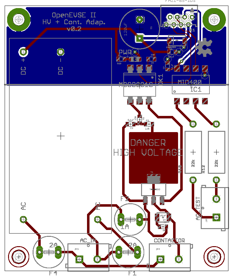
There isn't a lot to do to test it at the moment. I did hook power up to the two LINE terminals and the little green power LED came on. I shorted the two relay control pins on the mezzanine connector to ground and they clicked. Yay, I guess.

The big ugly washer over the spade terminal to ground is mainly because that spade terminal is too large to really work on a #4 screw without help. It's close to that via next to it, but that via is ground anyway.

I don't expect the logic/display boards to arrive in time for the July 4th holiday, unfortunately. So it will probably be the week after when I have something complete to show.

I think the result is going to be nice - it'll have the clean wiring of the DIY 30A board (no extra 22 gauge stuff for AC power and test), but in a smaller footprint. Plus, with the logic stuff going on the lid, it'll be much, much easier to troubleshoot, work on, or what not. And it'll be safer too, since in *principle*, you could put an insulated safety shield over the opening of the box and troubleshoot it with power applied, knowing that all of the stuff on the lid is isolated from the dangerous stuff.


On Sunday, June 8, 2014 1:23:40 PM UTC-7, Nicholas Sayer wrote:

Fishhawk

unread,
Jun 27, 2014, 9:10:24 AM6/27/14
to
That looks pretty good. Looking forward to seeing the display/logic board.

Any idea what the two-board set will eventually cost, compared to OpenEVSE with external relays and displays? I like things that are compact and low cost :)


Nicholas Sayer

unread,
Jun 27, 2014, 1:58:18 PM6/27/14
to open...@googlegroups.com
The power board is more expensive than I expected - partly because of the board, but mostly because of the power supply and relays. It's going to have to sell for around $75 or so. Shocking, I know, given how little there is on it.

The contactor version of the HV board will be much cheaper - probably closer to $40.

The logic/display board will likely be around $75. It has the LCD, and some of the parts on that board are in the $2 range in small quantities. So a combined $150 for the relay variant, or $115 for the contactor style (plus buying a contactor, My favorite from Grainger is $38.50 - $153.50 total). I haven't sat down and thoroughly analyzed it, but then I typically just fly by the seat of my pants on these things anyway.

From where I sit, that's more or less competitive. They both are very close to the same price. The relay version gives you L1 capability, but the contactor version goes all the way up to 50A.

Nicholas Sayer

unread,
Jun 28, 2014, 12:30:31 PM6/28/14
to open...@googlegroups.com
I've been able to save quite a bit of board space on the contactor version of the HV board by switching down to the VSK-S3-12 power supply. It's rated at 250 mA @ 12V. I've measured the 12 volt draw of a Hydra 3.1 logic board, and it's around 60 mA. I would expect that OpenEVSE II's logic board would be around the same - the extra ammeter and pilot generator aren't going to add significantly to that load. The opto-isolated triac only adds around 25 mA total to that, so that's well under half the load capacity of the supply.

Where it gets a bit more interesting is the idea of doing the same for the HV+Relay board. The relay has a coil resistance spec of 144 ohms, +/- 10%. That's 83 mA, but that's not how coils work - they have an inrush and then when the field is established, the steady state current is less. I set up a test with a pair of those relays and - sure enough, the two combined draw 170 mA, leaving 80 mA for the logic board. That's roughly in line with the 144 ohm stated resistance. But my VOM is too slow to show the inrush pulse.

The big question is how much inrush there is for how long, and whether the VSK-S3 can tolerate it. For one thing, running it at 100% rated power requires a temperature derate to 55 °C. I think that's fine, even for an outdoor portable unit (it *is* painted white).

It knocks $1.75 off the price of the board (at quantity 3) and about $2.50 off the price of the supply - quite a compelling savings, but not if the result is going to be unreliable.

Anybody have any thoughts?

chris1howell .

unread,
Jun 28, 2014, 2:05:21 PM6/28/14
to open...@googlegroups.com

I would keep a little margin, I usually shoot for at least 20% extra. I am considering building a similar micro board with a tiny 2w 5v power supply, the opto SSR, and smaller SMT parts.

Up until now I have used the same supply on all boards so I could take advantage of buying in quantity. If you have 4 boards each with a different supply you may pay more overall.

Not sure if you have been following juicebox but they just slashed the price of their board to $69, power supply $15 and relay $15. $99 for everything but enclosure is pretty good. The price is compelling even if it is not quite as flexible, stable or mature as the OpenEVSE design.

I am working very hard to lower cost and am targeting the Combo board for $89 and the standard board for $79. I am also trying to reduce the price of the LCDs as well...There are a lot of EVSE options out there today and it will be increasingly important to reduce cost.

Nick Sayer

unread,
Jun 28, 2014, 2:45:21 PM6/28/14
to open...@googlegroups.com
Yeah, the power LED actually blew the power budget anyway. 

But I am going to switch to the 3W supply for the upcoming Hydra AC board and the OpenEVSE II contactor board. The HV relay board will have to stick with the 5W module. 

(Un)Fortunately, when you sell one board every 90 days volume purchasing considerations are largely moot. 

Sent from my iPhone
--

Nicholas Sayer

unread,
Jul 8, 2014, 2:17:00 AM7/8/14
to open...@googlegroups.com
The prototype boards are back. Here's one built. Powerup testing is next... I'll report back when that's done.
IMG_3898.jpg

Nicholas Sayer

unread,
Jul 8, 2014, 3:33:42 AM7/8/14
to open...@googlegroups.com
I believe the first prototype is well on its way to being proven.

I loaded the RAPI branch of the firmware, which has the ammeter code. I fused and programmed the board and gave it 12 volts and it came right up. Of course, it immediately gave GFI self test and ground-fault errors, but I went into the UI and turned those off for now and the board booted up the rest of the way normally.

I mounted it on the lid. One of the first gotchas was that the LCDs that I buy seem to have #2 size holes and the hardware to attach the LCD to the lid is #4 - I had to ream the display holes out a bit for the screws to pass easily through.

I also used 1/4" standoffs, but I think Chris may use 1/8". I had to scavenge the longer #4 screws from the board to attach the display. I'll either use shorter standoffs to attach the board to its plate or get some more longer #4 screws.

With the logic/display board mounted on the lid, the lid easily fits into the box with almost a quarter inch of play in either horizontal direction, so the "wings" are not an issue. The follow on revision is even slightly narrower.

One of the screws to hold the board into the lid quite nearly touched a part on the board, but I believe this is already something I've checked on the next version. It still works perfectly, so far.

At rest, the board draws less than the Hydra - around 37 mA - which is quite a surprise, since there's very little difference between them when there's no load. With the two relay transistors turned on (but no relay coils connected), the load rises to around 60 mA. That's also somewhat of a surprise, since the transistors themselves shouldn't consume a great deal of power. I can only guess that the controller's CPU might be doing a bit more, since it has to update the charge time and ammeter in the display.

One more picture before bedtime. It's the logic board mounted and hooked up to an EV Sim.
IMG_3899.jpg

Nicholas Sayer

unread,
Jul 8, 2014, 11:14:54 AM7/8/14
to open...@googlegroups.com
More build pictures.

The connections on the logic board: On the bottom left is the pilot and ground screw (the ground can be left disconnected, as it's already connected through the mezzanine cable on two pins). The bottom middle blue screw terminals is the GFI and GFI test terminal. The bottom right is the ammeter CT. Upper right middle is the programming interface for updating the firmware. lower right middle is the FTDI connector. Immediately to the left of that is the DTR_RESET jumper. You can fuse and boot-load the controller with an Arduino bootloader and program over serial if you prefer by shorting that jumper. Upper left is the mezzanine cable.

You can also see the mounting plate mounted in the chassis. The HV board ground wire and the chassis bonding wire are connected to the ground bus.

Still to do:

1. Connect the GFI and CT coils to the logic board
2. Build and connect the mezzanine cable to the HV and logic boards
3. Crimp and connect the power cable to the LINE terminals on the relays and the ground bar
4. Crimp and connect a J1772 cable to the LOAD terminals on the relays and ground bar, passing the hots through the appropriate CTs.
5. Close the box and test.
IMG_3901.jpg
IMG_3900.jpg

Nicholas Sayer

unread,
Jul 8, 2014, 10:24:39 PM7/8/14
to open...@googlegroups.com
It's finished.

Ironically, the first time I powered it up, nothing happened. I was confused until I realized I had forgotten to build and connect the mezzanine cable. :)

There were a couple of minor firmware bugs, but I've submitted a pull request with fixes. There are no apparent hardware incompatibilities with the firmware as it is today. The hardware issue that caused the -12V power supply to short during program upload has been fixed successfully in the OpenEVSE prototype, so the design is, from a correctness perspective good to go (so far as I can tell).
IMG_3904.jpg
IMG_3906.jpg
IMG_3905.jpg

Fishhawk

unread,
Jul 9, 2014, 8:39:57 AM7/9/14
to open...@googlegroups.com
Looks nice! The display (mezzanine?) board looks like it doesn't fit in the case; must be the camera perspective (I think you mentioned above it fits, but it's tight). It's great that you are pursuing alternatives and expanding the options for the community; I wish I had the knowledge, desire, and time to do the same.

I understand the desire to separate the high voltage from low voltage, ability to swap out relay/contactor boards, etc. Still, from my limited experience (built two of them), the biggest issue for end builders like me is the number of wires that have to be connected. In my naïve perfect world, I would see a single board with the power supply, display, relays, and current transformer mounted, and some heavy-duty screw terminals for line power in and J1772 out. No other wires. I'd imagine that's quite an issue for handling the power in board traces, but I can dream. Yes, I know that would be a single (30amp-ish) current solution, but maybe there are some other options.

Are you using two current transformers? I hadn't seen that approach before. Could you explain why, or point me to a discussion why it would be good to use two?

Nick Sayer

unread,
Jul 9, 2014, 9:50:18 AM7/9/14
to open...@googlegroups.com

> On Jul 9, 2014, at 5:39 AM, Fishhawk <fishha...@gmail.com> wrote:
>
> Looks nice! The display (mezzanine?) board looks like it doesn't fit in the case; must be the camera perspective (I think you mentioned above it fits, but it's tight).

No, there’s a good quarter inch of lateral play when I set the lid on the carcass. It’s not a problem - and the follow on version is narrower still.

> It's great that you are pursuing alternatives and expanding the options for the community; I wish I had the knowledge, desire, and time to do the same.
>
> I understand the desire to separate the high voltage from low voltage, ability to swap out relay/contactor boards, etc. Still, from my limited experience (built two of them), the biggest issue for end builders like me is the number of wires that have to be connected.

I feel your pain - I build them too, and you’re right - it’s a lot of connections.

Board traces to handle 30A of current would need to be nearly an inch and a half wide. It’s not an effective use of board space, which is one of the most expensive “parts” of the build (my price is $1.66 per square inch).

I do think that this build helps to reduce the number of connections, because you don’t separately wire the AC supply and test functions or relay coils - board traces from the relays take care of that (that aspect of the design was stolen from Chris’ DIY 30A board). And moving forward, there won’t be any relay load-side connections anymore (no relay testing) since the new ground / voltage testing all happens on the AC input terminals.

> In my naïve perfect world, I would see a single board with the power supply, display, relays, and current transformer mounted, and some heavy-duty screw terminals for line power in and J1772 out. No other wires. I'd imagine that's quite an issue for handling the power in board traces, but I can dream. Yes, I know that would be a single (30amp-ish) current solution, but maybe there are some other options.
>

The CTs could be board-mounted, but the issue with that is that they would then be held rigidly in place. Depending on how the builder arranges things, that may put mechanical stresses on them, which would not be good for reliability.

When using a contactor, you generally want the high-current path to go directly through the contactor’s own terminals. They’re designed for high current. A contactor build would have only the two high current connections extra compared to this one. The contactor board would have 4 22 gauge wires to the contactor - two to siphon off AC power and two for the coil. Everything else would be the same.

> Are you using two current transformers? I hadn't seen that approach before. Could you explain why, or point me to a discussion why it would be good to use two?

One is an ammeter, the other is the GFI detector. You need two because they measure different things. The ammeter measures current passing through the vehicle, the GFI measures the difference between the current leaving on one hot line and the current returning on the other. Both hot lines pass through the GFI coil, but only one of them passes through the ammeter coil.

Nick Sayer

unread,
Jul 9, 2014, 10:05:24 AM7/9/14
to open...@googlegroups.com
Of course, now the issue I personally have is that I’m building up a collection of charging stations. I’ve got a Hydra, the MegaHydra, an OpenEVSE and an OpenEVSE II. Not to mention my old Versicharge.

I’m positively drowning in J1772 cables. :/

Anybody want to buy one? :)

Leigh van der Merwe

unread,
Aug 19, 2014, 10:00:16 PM8/19/14
to open...@googlegroups.com
Right!

Is the OpenEVSE II up fro sale yet?  i want to go for 240VAC 32A Continuous at my home, and this is the option that i want to go.

Any ideas when it will be up?

ta,

chris1howell .

unread,
Aug 19, 2014, 10:06:57 PM8/19/14
to open...@googlegroups.com

"OpenEVSE II" is a clone or as Nick (the designer) calls it a work alike. It will not be sold as an Official OpenEVSE product. Nick may sell boards on his site.

A new official board OpenEVSE v3 will be released next week that is designed for high current contactors. It also adds current measurement and "IEC Proximity Pilot" and cable lock/unlock for European users.

You received this message because you are subscribed to the Google Groups "OpenEVSE" group.
To unsubscribe from this group and stop receiving emails from it, send an email to openevse+u...@googlegroups.com.

Leigh van der Merwe

unread,
Aug 19, 2014, 10:08:55 PM8/19/14
to open...@googlegroups.com
Excellent!

that is the news i was after :)  Will it be sold as a kit?

thanks

chris1howell .

unread,
Aug 19, 2014, 10:11:07 PM8/19/14
to open...@googlegroups.com

Sure will....

--

Leigh van der Merwe

unread,
Aug 19, 2014, 10:11:50 PM8/19/14
to open...@googlegroups.com
yay!


--
You received this message because you are subscribed to a topic in the Google Groups "OpenEVSE" group.
To unsubscribe from this topic, visit https://groups.google.com/d/topic/openevse/SSf6WloBSVE/unsubscribe.
To unsubscribe from this group and all its topics, send an email to openevse+u...@googlegroups.com.

Nick Sayer

unread,
Aug 19, 2014, 10:49:45 PM8/19/14
to open...@googlegroups.com
I've been behind on other projects. The final prototype boards are in and just need to be built, and then I'll have them up for sale.

If you're in a hurry, though, you can buy a contactor adapter and use that with Chris' original OpenEVSE board. That would let you use a contactor as beefy as you like.

Leigh van der Merwe

unread,
Aug 19, 2014, 10:54:12 PM8/19/14
to open...@googlegroups.com
no no, it has been an expensive month for me, so i am happy to wait a little bit longer, not to mention that the DC drive controller in my car has popped a cap and needs to be sent to the US for repair (Zilla 1K).

I will wait, as i like the ideas of external interfaces that i can program my self.  You may recall that i wanted to build something that will allow me to charge at the same rate as my solar panels produce, to further reduce the costs/sustainability of the car.

ie, charge full pelt to 80%, then slow down to what ever the panels are producing to top it up.

cheers,

alansni...@gmail.com

unread,
Sep 11, 2014, 10:27:05 PM9/11/14
to
Is the new board almost ready?  I could use a new project.

Nick Sayer

unread,
Sep 11, 2014, 10:29:21 PM9/11/14
to open...@googlegroups.com
The boards have been sitting on my workbench for almost a month waiting for me to populate and test them. :(

I'm a bad maker. :(

I've been making crazy clocks and raspberry pi power supplies and battery boost iPhone charger gizmos and stuff like that.

I'll do it this weekend for sure - no more delays. :)

On Sep 11, 2014, at 7:27 PM, alansni...@gmail.com wrote:

Is the new board almost ready?  I could use a new project.

chris1howell .

unread,
Sep 12, 2014, 12:43:38 AM9/12/14
to open...@googlegroups.com

Danny ter Haar

unread,
Sep 12, 2014, 11:30:22 PM9/12/14
to open...@googlegroups.com
In the features I read:
-Current measurement with optional CT
Is that the same CT that is being used for CFGI ?

Is the software ready for current reading ?

chris1howell .

unread,
Sep 13, 2014, 12:07:08 AM9/13/14
to open...@googlegroups.com
The CT is different, it is the CR8450-1000. I will have some in stock next week. If you want one sooner here is the digikey link...

Yes the firmware is ready, version 3.2.2 has a compile time option for current measurement. If you need a HEX file I can send you one.

Chris

--

James Klafehn

unread,
Sep 13, 2014, 7:56:49 PM9/13/14
to open...@googlegroups.com

Great job on the new boards!

Just to let you know, the link you provided isn't working.

Danny ter Haar

unread,
Sep 14, 2014, 12:17:34 AM9/14/14
to open...@googlegroups.com
putting CR8450-1000 in the search fielded yielded:

http://www.digikey.com/product-search/en?x=27&y=19&lang=en&site=us&keywords=CR8450-100

Does that work for you ?

James Klafehn

unread,
Sep 14, 2014, 8:23:02 AM9/14/14
to open...@googlegroups.com

I didn't need it. I just wanted to let him know that the link wasn't working  but good job.

--

bpm...@gmail.com

unread,
Sep 30, 2014, 1:24:37 PM9/30/14
to
If you do decide to use the new current measurement on the v3, where do you connect the additional CT on the board?

Craig Kirkpatrick

unread,
Oct 17, 2014, 7:51:49 PM10/17/14
to open...@googlegroups.com
The V3 board has a 2-pin header just for the Amperage measuring CT. The same 3-pin still is there for the GFCI CT.
Reply all
Reply to author
Forward
0 new messages