Harwell Decatron Kit

Richard Scales
I had been interested in the idea of building a decatron based clock for quite some time when I learnt of the development of a 6 tube device which did exactly that.
I immediately registered my interest and watched as the project developed until it became available as a complete kit.
Subsequently, I had the opportunity of building one, and so I ordered up the ‘Harwell’ six tube decatron clock kit from sgitheach.org.uk.
It is a completely open-source project (hardware, software and case) and is available as a set of bare boards or as a kit with all the SMD components pre-loaded (which is what I chose).
Upon opening the box it was easy to see that the kit had been put together with considerable care and attention to detail. There are several major modules that make up the completed clock. Each module had its own set of components bagged separately. Within each bag, each component was individually bagged and labelled. This saves a lot of effort when working out which parts pertain to which module.
Similarly, the construction guide has been written with the same level of care and clarity. The instructions are clear and well supported by drawings and pictures which make the whole construction process an absolute pleasure.
The clock consists of a power supply, main board, tube board and front panel board.
Firstly, the power supply board has to supply not only 5V for the logic etc but also 170V and 500V – considerable care must be taken when handling these voltages. There are tests to be performed at every stage of the construction process – do not proceed until each test has been passed!
Next, there is the main board, this has the main control logic and also accommodates plug in modules for GPS or Wi-Fi (for time sync) as well as the main processor which comes pre-built on its own board.
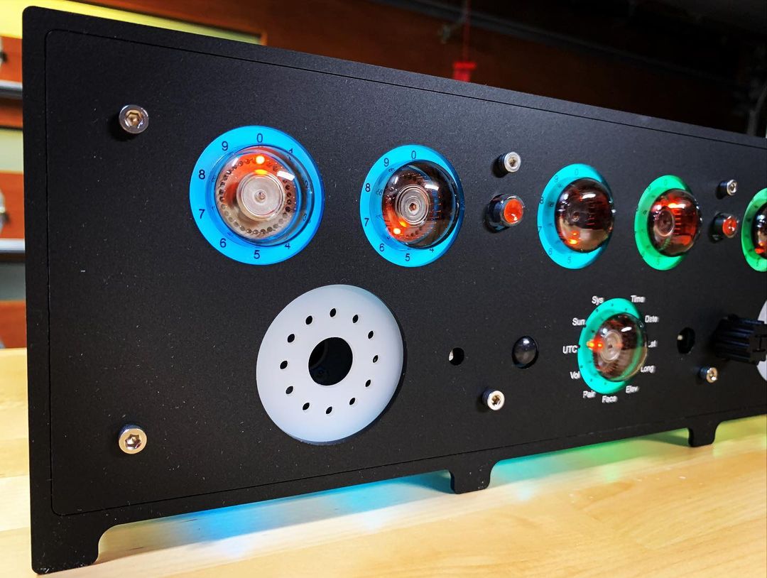
The tube board is next, this holds six GC10B type decatrons as well as a single GC12/4B decatron which is used to indicate what is being set by the rotary encoder on the front panel.
Finally, there is the ‘Bling’ board which provides tube back lighting as well as holding two small loudspeakers which are used for chimes and clock ticks.
As all the SMD (and there is a lot of it – 0603 being the smallest) had been pre-loaded – construction centred around the Through Hole components, board interconnections and the various mounting components. There are a lot of cleverly designed 3D printed parts which make this a lot easier.
Inter board connections are by both ribbon cable with IDC connectors and Dupont style crimped connections. No special tools are required and whilst I did already have the crimp tool – these can also be soldered to the various wires (supplied). The ribbon cable assemblies are easily completed using a vice.
I also got the kit for the housing which is as comprehensive as the electronics kit and equally well documented. It uses 3D printed parts to link the various laser cut acrylic parts which are ¼” thick making the completed case quite robust. A lot of the 3D printed parts are used to hold M4 nuts in place and whilst these are held quite firmly– I used a tiny spot of glue to make sure that they did not fall out whilst putting a screw in to place – otherwise it could be a lengthy disassemble/reassemble job just to get the missing nut back in to position!
Clever use of acrylic tubing as light guides makes the front panel illumination very even. The front panel itself appears to be screen printed in some way giving the completed unit an extremely professional finish. M4 and M3 fixings with Hex socket heads are used throughout.
The kit comes with a programmer board which is used not only for programming the various micros (there are three: The clock main processor, the tube board slave processor and the WiFi ESP8266 module) but also for monitoring the main controller during testing. It is possible to have the kit delivered with the two micros pre-loaded with the latest firmware.
Also included is a kit to make a nice 12V power supply - not the usual wall-wart variety but the sort that requires a ‘kettle’ lead (not included in the kit). The stand-alone power supply also has an optional laser cut acrylic case that follows similar styling and construction to the clock housing.
The tube board holds the individual sockets for each tube which have their mounting screws in slots. This allows sufficient rotation of each tube so that the ‘top’ position can point precisely to the ‘top’ – these tubes are specified to have the top in exactly the right place +/- 12 degrees – so it’s a necessary feature.
The ‘Bling’ board uses neopixels to provide lighting around each tube as well as various other strategic locations and under the case. 3D printed light guides are used extensively to ensure that light only goes where it is wanted.
The clock allows full customisation via its own programming language ‘Nuggle’ which I have not looked at yet though it looks very capable and seems to provide control over every aspect of the clock. All settings and programs are stored on an SD card which can be accessed by plugging it into another device or via a USB connection. Sets of settings are stored in ‘Faces’ and the supplied firmware comes pre-loaded with a number of pre-defined faces. More can be created and/or edited allowing extensive customisation and control to suit individual taste.
As well as a rotary encoder, a remote control is also provided. The clock also supports automatic dimming to suit the ambient light as well as a PIR detector for motion control activation.
The case kit includes everything needed to complete a really nice looking housing for the clock and consists mostly of cleverly designed 3D parts and laser cut (and engraved) ¼” acrylic panels.
It is important to follow the build sequence in order as each new part depends a lot on the previously constructed parts. Everything fits together nicely, and the completed unit is well proportioned and looks extremely professional in my humble opinion.
I mentioned that the entire project is ‘open source’, full details and documentation are available in a dropbox.
The entire build process was a joy from start to finish and the completed item exceeded all my expectations, and now I have my own little reminder of the “Wolverhampton Instrument for Teaching Computing from Harwell” – or “WITCH”. Details available here: https://en.wikipedia.org/wiki/Harwell_computer
There is an operational WITCH at the National Museum of Computing in the UK which is well worth a visit. https://www.tnmoc.org/