Coin cell nixie power supply
73 views
Skip to first unread message

Paul Andrews
Jun 1, 2017, 11:29:06 PM6/1/17
to neonixie-l
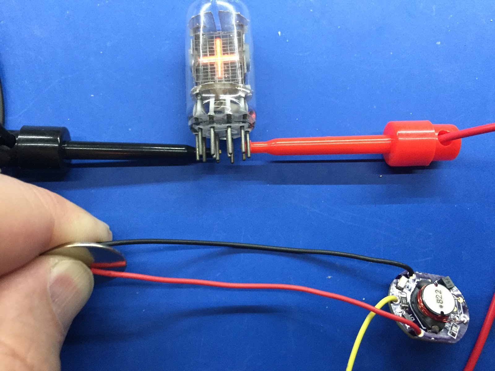
I thought I would share this little project (not mine, I just stumbled across it).The video is really well made and there is a link to the author's web site. So I ordered the parts so I could build it. In the meantime I simulated it in LTSpice. The simulation showed an unloaded voltage of around 130V and a loaded voltage of about 70V. The real thing seems to produce an unloaded voltage of around 200V. The loaded voltage (driving the tube you see in the picture) was around 140V.
BTW the design called for a 10K anode resistor, which always seemed optimistic to me, and did indeed turn out to be. I dropped it to 1K, (I had a choice of 10K or 1K given the SMD resistors I had). It worked much better, still the loaded current was only 0.15mA! I'm amazed the tube glows at all with that!
Here is a picture:
Paul Andrews
Jun 2, 2017, 11:13:56 PM6/2/17
to neonixie-l
I did some measurements. The coin cell is pumping out about 40mA at around 2V, i.e. 0.08 watts. Measurements on the other end are about 0.15mA x 140V, i.e. 0.21 watts. So about 25% efficiency..
The low voltage is because the current draw is excessive for this type of battery, which is rated at about 3mA continuous and about 30mA peak. The voltage drops rapidly over time.
Reply all
Reply to author
Forward
0 new messages