VFD Filament Current
982 views
Skip to first unread message

gregebert
Sep 13, 2019, 4:56:48 PM9/13/19
to neonixie-l
I thought this was worthy of a separate discussion.
Small VFDs, and even NIMO tubes, use the filament as the cathode and in doing so the filament is the sole source of electrons to produce the glowing segments. So, some of the filament current is going towards heating of the filament and some of it is going to the segments. For NIMO tubes, this is negligible because it's on the order of 30uA; for small VFDs it's probably a few mA.
But with big VFDs, like the ILC1-1/8, the segment currents are fairly large like 30-40mA each and on top of that there is the grid which basically amplifies the electron stream for brighter operation. All of those will add several hundred mA of current to the filament in addition to what is required for heating. So I'm a little confused about what the overall specs are for filament current on these big VFDs.
I'm fairly certain that driving the filament with an AC source results in a net cancellation of this "extra" current, and if you measured the filament current with an AC ammeter you would not detect it (only the current to heat the filament is measurable). However, when you measure the current from the center-tap of the AC source to GND, you will definitely detect it. In fact, if the filament was driven by a floating AC source, there would be no glowing segments. Another reason why you dont want to use DC on the filament is that it sets up a small voltage difference across the display and it would contribute to non-uniform illumination; with AC, this is averaged over time and not visible to your eyes. I recall this being discussed awhile back.
Has anyone here built their own jumbo VFD clock and had it running for a few years ?
The other thing to know is that driving the grid on these large tubes with AC vs DC will likely affect the lifetime. When the grid and filaments are DC, there is a static electric field in the tube, and you can see darker vs lighter bands on the segments due to the electric field as it gets warped between the grid and filament. Over time, this will likely cause uneven wearout on the phosphor. When the grid is driven by AC or varying DC, the electric field changes, and the segment glow looks uniform. I dont yet have any observations for AC-filament drive.
The VFD on my kitchen stove is 13 years old, and it clearly has darker bands closest to the filaments where the phosphor has been bombarded-away by the electrons.

David Eustace
Sep 13, 2019, 5:22:59 PM9/13/19
to neoni...@googlegroups.com
This is certainly a timely discussion for me. I'm working on a clock with DG12B tubes and am starting to see the influence of this.
While at the protyping stage I've just been running the filaments, which need 0.8V, off a buck converter running down the 5V output from the arduino nano. This has worked perfectly well for driving the tubes statically, i.e. just displaying 1-9 on all tubes simultaneously. I've also seen plenty of projects online, including one with ILC1-1/8 tubes, which, after looking at incorporating AC into the circuit, have simply given up and driven from DC and not seen adverse effects in the quality of the display, in theory becuase the multiplexing nature of the final design negated the impact.
I had been hoping, since the DG12B tubes are fairly small, to take a similar approach and keep things simple. But I'm working with someone on the coding and have found that with the multiplexing set-up I'm seeing the variance you're talking about. I've attached a picture. The central sgements are clearly brighter than the rest. It seems pretty clear that the multiplexing aspect has a big impact on the uniformity.
It's worth saying though that at this prototyping stage, the segment brightness also varies pretty dramatically with the quality of the wired connections. A wee wiggle of a wire here and there can have an impact.
When all is said and done, I know in my heart I'm going to have to build in an AC supply. Does anyone have any recommmendations for the absolute easiest way to do this? John S has recommended the LM9022 /LM4871 but is there anything simpler,?
--
You received this message because you are subscribed to the Google Groups "neonixie-l" group.
To unsubscribe from this group and stop receiving emails from it, send an email to neonixie-l+...@googlegroups.com.
To view this discussion on the web, visit https://groups.google.com/d/msgid/neonixie-l/95bf90b1-6754-4c12-ac07-a685dc7fc37b%40googlegroups.com.
gregebert
Sep 13, 2019, 6:26:01 PM9/13/19
to neonixie-l
Those are very cool-looking tubes !!
Are you connecting filaments in-series ? If so, when you run them on DC there will n=be a net bias and that will cause non-uniform brightness
Even if the filaments are in-parallel, there will be some DC bias that makes some segments dimmer.
A center-tapped AC filament transformer with the center tap tied to circuit GND should work nicely. If you need dropping resistors, be sure to put equal-valued on each side of the transformer. Dont use a single resistor because it will produce an offset that affects brightness.
David Eustace
Sep 13, 2019, 6:42:28 PM9/13/19
to neoni...@googlegroups.com
I'm running the filaments in series but even then the first one is brightest and the subsequent ones a little dimmer one after the other. I don't think that's an ac/dc problem though (or could it be?). I need to think a little more about the circuit.
Thanks for the transformer tip, I'll go down that route.
--
You received this message because you are subscribed to the Google Groups "neonixie-l" group.
To unsubscribe from this group and stop receiving emails from it, send an email to neonixie-l+...@googlegroups.com.
To view this discussion on the web, visit https://groups.google.com/d/msgid/neonixie-l/9d290194-83e8-4eed-a5d3-03e114bf80b2%40googlegroups.com.

ZY
Sep 13, 2019, 8:42:49 PM9/13/19
to neonixie-l
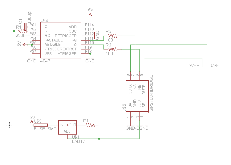
I took a look at the LM9022 datasheet and it's drive method seems similar to my H-bridge + oscillator. I've built and tested it but haven't ran it long term with my ILC1-1/7s. I'm still looking for anything to improve on before I finalize the driver for my clock.
gregebert
Sep 13, 2019, 9:58:52 PM9/13/19
to neonixie-l
I'm pretty sure the the reason for progressive dimness is because of the DC bias is different on each tube. The brightest one is closest to GND; as the tubes get closer to the + filament supply, they get dimmer. I suggest running them in-parallel from an AC source, or a +/- square-wave that 'ZY' mentions below.

Alex
Sep 14, 2019, 7:46:50 AM9/14/19
to neonixie-l
I agree with Greg, the voltage WRT Gnd is important for brightness (as its what gives the electrons the incentive to move in the first place). Series connected filaments on individual tube VFDs will give you a nice demonstration of the same aformentioned problems with linearity of brightness as DC driven filaments for long VFD displays.
By far the most used commercial approach I see (e.g. Nortake / Futaba VFD panels that run on 5vdc) is to have a small PCB mounted coupled inductor (fancy name for a smal high frequency transformer really) driven by a half or full H-Bridge arrangement. Secondary winding driving the filament with a center tap to main Ground.
Other lazy way applcable here is to just use a small 50hz mains transformer as a PSU, with a center tapped secondary, center tied to ground - like virtually every VFD bedside alarm clock ever made... I doubt it would affect it if you also rectified each end of the winding with a diode and used it for your electronics (I think the last VFD alarm clock I killed for parts only had one center tapped winding on its transformer. They also tap off one side pre-rectification and square it up for timekeeping...
As an aside, those DG12B tubes are beautiful!

Paul Andrews
Sep 14, 2019, 8:22:36 AM9/14/19
to neonixie-l
Papers I have read also emphasize the need to bias the filament above the cutoff voltage of the grid or anode, so I assume if the center tap is attached to ground, that the cutoff voltage of the anode or grid is significantly below that? In fact it would have to be below the negative swing of the AC. It might be easier to connect the center tap to a positive voltage? See the diagram in the "Cutoff bias voltage" section here: https://www.futaba.co.jp/en/display/vfdinfo/vinfo_kudo_1.html

5-ht
Sep 14, 2019, 8:55:13 PM9/14/19
to neonixie-l
FYI, Noritake has some good information regarding VFD driving and filament bias:
Mark
Alex
Sep 15, 2019, 6:03:08 AM9/15/19
to neonixie-l
I am trying to get my head around that, but I see the diagram you mention:
"If the filament potential is lower than the anode and grid cut off
voltage, thermionic electrons can reach the anode and cause illumination
of the phosphor. The filament
bias voltage should be increased to prevent this problem. Generally, a zener diode is used to obtain the bias voltage."
bias voltage should be increased to prevent this problem. Generally, a zener diode is used to obtain the bias voltage."
I guess it could be summarised as advantagous to put the center tap of the filament supply a diode drop or two above ground, such that when the grids or anodes are pulled to ground (to turn them off) they then appear slightly negative to the filament and thus are fully disuaded from illuminating. Mind you, I would think that any raising of the filament center point would also require a slightly higher anode potential to give the same brightness?
Another interesting point on that page is that VFD displays designed for DC applications (e.g. pocket calculators (!)) can have sloped filaments to mitigate the brightness gradient...
Paul Andrews
Sep 15, 2019, 7:25:25 AM9/15/19
to neoni...@googlegroups.com
That would be what I would infer too (that the anode voltage would have to be suitably higher to maintain the same brightness).
This reference design shows an interesting way to produce an oscillating filament voltage - basically using an additional secondary winding of the transformer used in the boost converter for the anode voltage: https://pdfserv.maximintegrated.com/en/an/AN4363.pdf. The transformer doesn’t seem to be made any more, which seems to be an issue with this approach as VFDs become increasingly obsolete.
--
You received this message because you are subscribed to a topic in the Google Groups "neonixie-l" group.
To unsubscribe from this topic, visit https://groups.google.com/d/topic/neonixie-l/R89iFm3Ndhg/unsubscribe.
To unsubscribe from this group and all its topics, send an email to neonixie-l+...@googlegroups.com.
To view this discussion on the web, visit https://groups.google.com/d/msgid/neonixie-l/794103de-d808-477d-9a26-161d15d9f3cc%40googlegroups.com.
gregebert
Sep 15, 2019, 12:32:55 PM9/15/19
to neonixie-l
NIMO tubes operate similarly to VFD's that have a grid; I drive the center-tap of the filament transformer from a DAC ( + amplifier) to give me software control. You can clearly see that if the grid is not sufficiently negative (ie, grid=0 volts with filament biased positively), other numerals start illuminating. I'll try to post a video.

Tomasz Kowalczyk
Sep 16, 2019, 4:35:34 PM9/16/19
to neonixie-l
VFDs are basically directly heated triodes. To reach cutoff, the grid has to be at some negative potential in respect to the cathode. It is just easier to elevate the cathode above ground and swing the grids to ground than creating yet another voltage rail.
The question is - if the filaments were heated by a transformer with center tap connected to, let's say, 5V, would there be any current flow from or into the 5V rail? The grid + anode current has to go somewhere, after all. It might mean that the elevated voltage has to be low impedance, and most likely - it has to be able to sink current, which standard linear regulators can't do. This is something that concerns me, as I own four ILC1-1/7 and plan to make a clock out of them. Their anode and grid currents are dominant compared to any other circuitry.
The question is - if the filaments were heated by a transformer with center tap connected to, let's say, 5V, would there be any current flow from or into the 5V rail? The grid + anode current has to go somewhere, after all. It might mean that the elevated voltage has to be low impedance, and most likely - it has to be able to sink current, which standard linear regulators can't do. This is something that concerns me, as I own four ILC1-1/7 and plan to make a clock out of them. Their anode and grid currents are dominant compared to any other circuitry.
gregebert
Sep 16, 2019, 5:23:47 PM9/16/19
to neonixie-l
Yes! That's exactly what happens. The current through the center-tap is the sum of the anode (segment) current and the grid current. And the peak current through the filament wires is actually greater than just the current to heat the filaments.
Tomasz - As you found out, those VFDs draw a lot of current. I have a future design for a 6-tube ILC1-1/8 (smaller tubes than the ILC1-1/7) and I'm just going to use a high-current filament transformer with the center-tap at GND. Grids will NOT be pure DC; closer to full-wave rectified around 15-16V. Segment anodes will be pure DC around 36-40V with current-regulators and non-multiplexed.
I actually have an Op-amp summer+ADC+Software to monitor the current thru the center-rap on my NIMO clock to determine the tube health, though it's orders of magnitude smaller (30uA per tube).

Richard Scales
Sep 14, 2022, 4:02:24 AM9/14/22
to neonixie-l
Hello everyone,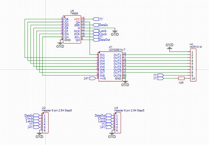
I have just managed to acquire a set of these and would ideally like to drive them the best possible way.
I had initially though about a 5V for the filament and then 24V for the cathodes and grid.
I had initially though about a 5V for the filament and then 24V for the cathodes and grid.
The clock would only have segments activated when someone is nearby - the segments will not be left on all of the time.
Now I read about A/C supply to the filaments and wonder if I should be going that way.
Would anyone be able to post their findings and/or suggest the right way forward?
Would anyone be able to post their findings and/or suggest the right way forward?
I just noted that the picture above shows the connection for the grid (pin 9 on H1) connected to 5V and not the 24V as used on the cathodes.
The more I think about it - the less clear this all becomes!
I need to get it right in my head before I go breaking something and then I would like to get the best possible result via reasonably straight forward means.
Would anyone be able to point me in the right direction and/or share proven drive methods?
- Richard
Richard Scales
Sep 14, 2022, 4:16:12 AM9/14/22
to neonixie-l
I think I already see blunders in my original post - the filament is the cathode (I think) at 5V, the segments (individual anodes) at 25V giving a 19V difference over the grid which is at 5V.
I am unsure as to the correct value of the series resistor for the heaters- 10R has been used by others though I would prefer to know how that was calculated and indeed whether there are significant gains to be made by moving to an A/C drive for the filaments.
I am unsure as to the correct value of the series resistor for the heaters- 10R has been used by others though I would prefer to know how that was calculated and indeed whether there are significant gains to be made by moving to an A/C drive for the filaments.
- Richard

Adrian Godwin
Sep 14, 2022, 5:42:49 AM9/14/22
to neoni...@googlegroups.com
Using DC for the filament means there is more accelerating voltage at one end than the other and results in a noticeable difference in brightness.
I have wondered if it could be solved without a transformer by driving the filament with a h-bridge.
--
You received this message because you are subscribed to the Google Groups "neonixie-l" group.
To unsubscribe from this group and stop receiving emails from it, send an email to neonixie-l+...@googlegroups.com.
To view this discussion on the web, visit https://groups.google.com/d/msgid/neonixie-l/88406a7a-3854-4dc2-bf24-8a33f769811en%40googlegroups.com.

David Pye
Sep 14, 2022, 6:26:28 AM9/14/22
to neoni...@googlegroups.com
It can indeed.....
For single digit tubes the brightness gradient isn't usually noticeable but for the multidigit ones eg the one from the adafruit iceclock, it certainly is.
David
To view this discussion on the web, visit https://groups.google.com/d/msgid/neonixie-l/CALiMYruQ0Qbm741UYeurekUGAPWVPU_GnTYCHurMpfO1odi0_g%40mail.gmail.com.
Paul Andrews
Sep 14, 2022, 9:20:24 AM9/14/22
to neonixie-l
I spent a long time trying to figure out if an AC filament drive was worth it. I tried multiple AC circuits. In the end, they all suffered from the same problem - the voltage varied with the load. This was a killer for me, as I wanted the circuit to work for multiple VFD types. In the end it just wasn't worth trying to develop a regulated AC driver for several reasons.
- I was driving single-digit VFDs and I wanted to drive them in parallel so that if one failed, the others stayed lit.
- If one failed, the voltage across the filaments of the others had to stay the same (so no circuit whose voltage varied because of the load).
- The filament length was relatively short (small tubes), so the voltage gradient was small enough that there was no detectable difference in brightness across the length of the filament.
Paul Andrews
Sep 14, 2022, 9:25:57 AM9/14/22
to neonixie-l
I don't know the specs for these specific tubes, but a resistor in series with the filament servers a couple of purposes:
- It reduces the inrush current (i.e. when the filaments are cold). The resistance of the filaments is low when they are cold, so if you put the steady-state voltage across them in that state, there will be a much greater current. For this purpose the series resistor value should be high enough to drop that current within the specified limits of the filament.
- Putting a resistor between 0V and the filament raises the base voltage of the filament above 0V. If the tube has a grid, it is typically specified to be at a negative voltage with respect to the filament so that it can be guaranteed to cut off the current when pulled to that voltage. An easy way to achieve this negative bias is to raise the filament voltage above 0V and keep the grid at 0V.
Paul Andrews
Sep 14, 2022, 9:35:29 AM9/14/22
to neonixie-l
Arghh - I accidentally hit send on that last one. So anyway, if you don't plan to use the grid to turn the tube off, you can wire it to the segment positive voltage and ignore the need for a bias. You still might want to put the series resistor in though. The exact value you use is going to depend on the cold and hot resistance of the filament. Oh, also if it wasn't clear from my second point, the series resistor acts as a voltage divider, so you have to figure out what the total total voltage across that resistor and filament should be.
In my VFD clock I needed two different filament voltages, so I use a buck converter to get the larger of the two and used a series resistor to produce the lower. In retrospect it might have been better to use series resistors for both and have a higher regulated voltage - the resistances are all very small and it would help smooth over any variations in individual tubes and resistors.
So the easiest way to figure out these values is to measure the filament resistance when cold to get an initial value for the series resistor, then start experimenting and measuring.
gregebert
Sep 14, 2022, 11:26:23 AM9/14/22
to neonixie-l
Another thing to consider is when to turn filaments on and off. Having a PIR motion sensor to turn-off the segment supply is important, because long-term you will see dark regions on the phosphor closest to the filament.
Turning filaments on and off too many times will wear them out from thermal cycling. Having series resistance to reduce the peak inrush current will help a lot to extend their life. But leaving them on 24/7 might lead to wearout as well.
I have the same issue with my NIMO tube clock (I expect to post more details and a video in a few weeks). NIMO tubes are basically irreplaceable, so burning-out a filament is a death sentence for the tube. For now, I have programable timers for 3 states:
cold (filaments off)
warm (filaments on, high voltage off)
on (filaments and HV on) - Tubes are readable
To go from cold-to-warm, the software requires a few seconds of PIR activity so that peeking into the room wont trigger it.
Warm-to-on will happen with any PIR activity.
What I dont yet know is how long I should keep the clock in the warm state. Too short, and there will be excessive filament cycling. Too long, and it leads to wearout. For now, the warm timeout is 100 seconds, and the cold timeout is 24 hours. After the novelty of this clock wears off, it will be put in standby mode where it's just keeping time and the display is disabled.
Richard Scales
Sep 15, 2022, 11:33:25 PM9/15/22
to neonixie-l
Thank you all for your input.
Currently (!) I am looking at a small A/C driver - one per display - I should be able to report back once tests have been performed - waiting on board fabrication - I would also only have the whole thing 'on' once triggered (that includes both filament and segment supplies) so most of the time - the device will be 'cold'.
As for the segments - the plan is to use a 74595 coupled to a TD62783 for switching the 24V - each tube will attach to an individual PCB - the PCB's can then be chained together - 6 planned for this clock plus a couple of colons using IV-26's (multiple dot action is planned).
Reply all
Reply to author
Forward
0 new messages