Problem with Wi-node 2.0 and digital Pin 4

Philomenale
Hello,
I have a Wi-Node 2 with a strange behavior. It's seems to be impossible to use RFM12 and motor driver at same times.

When digital pin 4 is configured as output, the "rf12_recvDone()" don't work.
For example with the "timedsend" from jeelib available at following adress
https://github.com/jcw/jeelib/tree/master/examples/RF12/timedSend
When I had the line pinMode( 4 , OUTPUT); in the setup function, the test rf12_recvDone() always fail.
/// @dir timedSend
/// Experiment with time-controlled periodic transmission.
// 2011-06-24 <jc@wippler.nl> http://opensource.org/licenses/mit-license.php
#include "../../LibRF12/JeeLib.h"
MilliTimer sendTimer;
byte pending;
word seqnum;
void setup () {
Serial.begin(57600);
Serial.println("\n[timedSend]");
rf12_initialize(25, RF12_868MHZ, 4);
pinMode( 4 , OUTPUT); // <-- This line causes the failure
}
void loop () {
if (rf12_recvDone() && rf12_crc == 0 && rf12_len == 2) {
sendTimer.set(0);
Serial.print(" #");
Serial.print(seqnum);
Serial.print(" start: ");
Serial.print(rf12_data[0], DEC);
Serial.print(" recvd: ");
Serial.println(rf12_data[1], DEC);
}
if (sendTimer.poll(2096))
pending = 1;
if (pending && rf12_canSend()) {
pending = 0;
rf12_sendStart(RF12_HDR_ACK, "hello!", 6);
++seqnum;
}
}
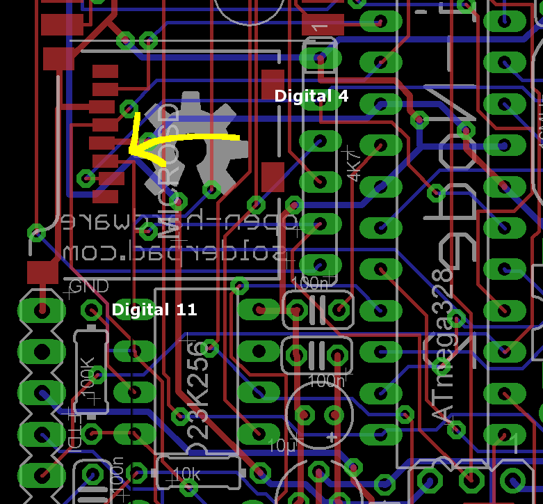
I didn't see anything in the solders...

Have you got any idea ?
Thanks for your help !
Philomenale (french nanode passionate).

SomeRandomBloke
Philomenale