Nano DLP Setup/Config/Stuff :) and first print
3,874 views
Skip to first unread message

Ryan LaBarre
Jan 15, 2016, 5:19:29 PM1/15/16
to mUVe 3D Support Group
So im not sure how Muve3d support wants things handled, but i figure at some point that main thread will be cleaned up , as I dont think it was ever intended to be a troubleshooting thread.
So id like to talk about a few things im experiencing now.
Just so you know, I AM PRINTING> it is working.
1. Servo works , but is slow... can i speed it up?
2. Projector control works - for me it was ttyusb2
3. Peel mechanism seems strange :) Im used to straight up and straight down. THis is set to raise left, then right, then down. I assume this is to help with the forces.
4. Peel speeds seem fairly slow, compared to what I used before. I will play with those.
5. I wish nanodlp had a built in slicer. Having to use three programs if we want support is pretty brutal :). However now having the option in slicer to calculate infill is nice. CW didnt give that. BTW 15% is a REALLY good infill for DLP
6. Im exhausted from this project.
7. Im not sure exactly where to hook up a 12v? or 24v? fan to this ramps. I tried D9 but that didnt work. I want an always on fan for the side of the unit to cool the ramps. I did not need cooling on my smoothie, because it never got hot.
8. Ok, it just kicked in to the higher layer peel speeds now that rocks. Much better, and its still detaching, i can look under it and see the FEP pop. Nice speeds there.
9. Im exhausted from this project.
10. I am going to try the camera module next. I think in the mail today i should have my HDMI housing + extension dealy. My plan is to print replacement acrylic (i have a PLA wall now in my vat) for my 2nd vat, make a square cutout in the wall, incorporate the camera inside the vat and record timelapse from inside the vat through the Rapsberry pi. This excites me :)
11. Im still exhaused from this project.
Ryan LaBarre
Jan 15, 2016, 8:19:59 PM1/15/16
to mUVe 3D Support Group
So, my first print turned out great... Quality was as expected the ONLY difference is its narrower then previously printed.
Its the same height, so i know the layer height and steps are good, but its noticeably narrower, skinnier.
what would cause this?
thanks
Message has been deleted
Ryan LaBarre
Jan 15, 2016, 8:22:46 PM1/15/16
to mUVe 3D Support Group
XY is 62.5 as the math works out for me, so that should be ok. Slicers metrics are just for the visible build area, not the part itself. its confusing

mUVe 3D Admin
Jan 16, 2016, 10:47:48 AM1/16/16
to mUVe 3D Support Group
Ryan,
Your measurements from the projector need to be exact, you also need to enter those measurements into Slic3r before slicing any SVGs. Before you load the slices to the printer, the printing profile must have the correct X/Y micron settings entered, it cannot be entered or changed after the upload.
If all of those pieces are correct then it should come out in the proper dimensions. If it's not then something isn't correct in one of those locations, or we have a bug somewhere.
mUVe 3D Support
Ryan LaBarre
Jan 16, 2016, 10:55:22 AM1/16/16
to mUVe 3D Support Group
Yep.. after i posted this i thought to myself if im making "plates" in slicer, then its not just exporting the object, but instead the entire plate, which means those measurements need to be right in there, not just generic :)
so we will see how it looks
Ryan LaBarre
Jan 17, 2016, 1:07:38 PM1/17/16
to mUVe 3D Support Group
so measurements are good. i can change the peel, but now, literally just since the nanodlp upgrade my parts dont stick, LIKE AT ALL :)
my bed is tight to the FEP, everything looks good. sounds good, but it is totally peeling away. like nothing on the plate at all.
ive tried 20 s cure base layers (10) and 40 seconds,20 was my setting before the change.
The ONLY things that have changed are the Software, and the Peel mechanism. Before I had it come straight up 6mm.
any ideas?
Ryan LaBarre
Jan 17, 2016, 11:06:49 PM1/17/16
to mUVe 3D Support Group
Trying a larger print with 60 second base cure time, which would be 3X more than ive ever had to use on this MJ black, but i guess we will see.
mUVe 3D Admin
Jan 18, 2016, 8:58:25 AM1/18/16
to mUVe 3D Support Group
Ryan.
All of the default profiles that we sent with the nanoDLP system are for a 50 second base layer. That's a good start point.
mUVe 3D Support
Ryan LaBarre
Jan 18, 2016, 10:11:25 AM1/18/16
to mUVe 3D Support Group
60 seconds still didnt work... I do think the base layers seemed somewhat ok though. Ill keep working at it.
So that begs the question. What the heck changed that would up the cure time by 3x by just changing software? it doesnt make any sense. Its the same beam of light shining on the same resin.

Hellenicopter
Jan 18, 2016, 10:28:45 AM1/18/16
to mUVe 3D Support Group
Ryan,
Don't forget that what has changed is the HDMI output. Not all outputs are the same and they don't carry the same picture information as far as I know.
Maybe you should check the HDMI format of the Pi w.r.t. your previous setup. I have had issues like that even at the projector level (full color range HDMI w.r.t. normal range).
Cheers

Matthew Caron
Jan 18, 2016, 10:36:50 AM1/18/16
to mUVe 3D Support Group
Ryan,
The peel mechanism you describe is the "standard" mUVe peel move.
The way I'm avoiding getting exhausted is by spreding things out.
There is no technical reason why NanoDLP can't do the slicing itself, but the more I think about this, the more I'm kind of "meh" on it. At the very least, you want software on a real computer to do a plate layout (unless someone does some wiz SVG stuf on the web UI to do it, which may be a cool roadmap item but isn't super necessary). At that point, you're already using 2 pieces of software. So, what's the difference if you slice it in software 1 vs, software 2?
As for eliminating the third piece, I think that having Slic3r do the top features that Meshmixer currently does would definitely be an improvement (I'm thinking support generation, part orientation and hollowing). Since Slic3r is open source, adding this is possible for those of us on the outside. Further, since, IIRC, it's mostly Perl.. well, I speak Perl. :-) I'm not saying I'll definitely have the time to start hacking on it, but it's at least a possibility, and is something in which I'm interested.
Ryan LaBarre
Jan 18, 2016, 10:44:57 AM1/18/16
to mUVe 3D Support Group
well, i will say that If I have to triple my cure times because of nanodlp, ill be going back to the old way with my smoothie haha.
I will just try to cure the crap out of this stuff and see what happens haha
mUVe 3D Admin
Jan 18, 2016, 3:30:29 PM1/18/16
to mUVe 3D Support Group
Ryan,
Your issues definitely sound related to the Z axis 0 point, resin not being mixed enough, settled resin pigment, or too low a cure time for your standard layers.
We've been testing nanoDLP extensively and have had no issues with initial adhesion or layer cure times when compared to the desktop software. It's identical.
mUVe 3D Support
Ryan LaBarre
Jan 18, 2016, 3:34:32 PM1/18/16
to mUVe 3D Support Group
Thats really strange...
So I think a BIG part of my problem was in slicer, i didnt realize you had to save EACH page separately, so the layers defaulted back to 3mm, so im sure that plays a role in how its sliced up.
.3mm and .05mm big difference. However in my first print since making the changes, we had what i think was cure issues.
So im trying 3x previous cure base layers, and 2x previous cure main layers.
Pigment settling shouldnt be an issue, i mix it up well before each print. Z height is good. when i home, i see all four screws well and the entire plate. .
mUVe 3D Admin
Jan 18, 2016, 3:38:08 PM1/18/16
to mUVe 3D Support Group
Matthew,
We kind of agree with you on that. A desktop is leaps and bounds more useful in terms of accessing your data, setting up prints, overall general CAD usage hitting points. Things that aren't really going to come through if we move to a full nanoDLP based solution.
However I see some opportunities still in there. Auto-plating is a genuine possibility, and it's not impossible to get a CAD preview window in a web browser either. There's probably even some free code out there already on GitHub. There's no reason it can't be done outside of nanoDLP either. We can run more processes in the background, so long as we can dump an SVG to a good location, at the proper scale. I'm sure we can get the folks at nanoDLP to add a local file import area for SVGs.
mUVe 3D Admin
Jan 18, 2016, 3:40:17 PM1/18/16
to mUVe 3D Support Group
Ryan,
Yep, that's definitely it. The output of the machine from the 2 different softwares should be identical. So long as the settings are in order.
Happy printing!
Oh, I think we're getting the custom version with a proper homing button, Z control, build plate tilting, etc in the next day or so. Keep on the look out for the new release, we'll definitely have blog post about it.
mUVe 3D Support
Matthew Caron
Jan 18, 2016, 3:40:57 PM1/18/16
to mUVe 3D Support Group
If you can batch upload a pile of .STL files and it auto plates, orients and supports them (ideally hollowing them too), with previews, etc. then that would be brilliant. I'm not saying that it's *impossible* - everything is possible. I'm merely saying that, for now, this workflow makes sense, because the other setup is a lot of work, so will likely take some time to get done. But, if the NanoDLP guys want to work on it, I'm sure we can find folks here to try it.
Ryan LaBarre
Jan 18, 2016, 3:53:14 PM1/18/16
to mUVe 3D Support Group
Muve3d should just buy a couple VMs on the AWS cloud portal that we can remote in to and run instances of Slicer in the cloud (shit maybe ill just do that anyway). Then we can make chances to the plates and upload them without needing to be at "Our" pc
Ryan LaBarre
Jan 18, 2016, 5:15:54 PM1/18/16
to mUVe 3D Support Group
btw, the last print with 60 sec base + 10 second other layers finished. it looks ok. not great... maybe overcure.
So im running it at 40 sec base, and 8 second other layers which is close to where i had it before.
However, the part came out narrow again, same height as it should, but narrow, like the resolution is still off.. so i measured again before this print... i guess we will see :). my setting in my print profile was off slightly, like 4 microns, which shouldnt make that big of a difference i wouldnt think. ive adjusted it, we will see.
Ryan LaBarre
Jan 19, 2016, 9:41:15 AM1/19/16
to mUVe 3D Support Group
ok. so extending my cure time to 10 seconds per layer seems to have done the trick.. However 6 seconds - 10 seconds is a BIG difference in time over the course of 1000 layers.
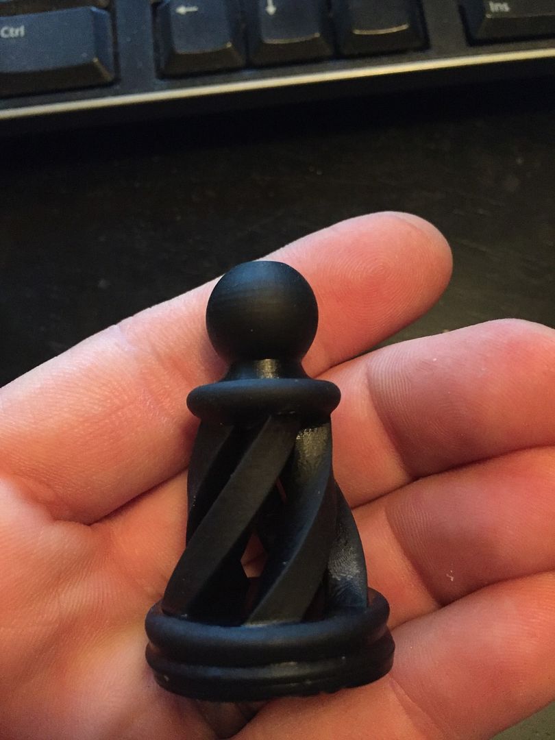
This is super bizarre too... So im testing with chess piece pawns like i always do.
I do 50% scale so it doesnt take forever. well last night i printed a piece, it worked.
I powered off the PI, hooked up the new camera vat, plugged it back in and went to the plates tab and started printing.
Low and behold the scale was set back to 100%, however the part still printed at the scaled height. so it was super smooshed down.
Really strange. Moral of the story. After a reboot, toss out your plates and re make them to be safe.
Hellenicopter
Jan 19, 2016, 10:47:00 AM1/19/16
to mUVe 3D Support Group
Hi Ryan,
As I have already written in a previous post, I think that your HDMI from the Pi doesn't put out the full color range and this extends your exposure times.
Check the config of your Pi w.r.t. HDMI (e.g. here).
I have had a similar problem with my projector. Its setting was not allowing the full color range from HDMI and this had made the exposure times go through the roof...
Cheers
Ryan LaBarre
Jan 19, 2016, 11:07:39 AM1/19/16
to mUVe 3D Support Group
Gotcha. i must have missed that one.
So im in the config.txt and it looks like the resolution defaults to 640x480 unless you change it to hdmi_mode = 16 which is 1080p. I know you are broadcasting a different spectrum of light at vga rather than HDMI
is that the setting im looking for.
the only WRT i know (that you mentioned above) has to do with networking haha :)
thanks.
Hellenicopter
Jan 19, 2016, 11:19:58 AM1/19/16
to mUVe 3D Support Group
I would check the setting "hdmi_pixel_encoding" and I would set it to 2 to force the RGB full. I suspect that this will output the full color range.
You may have to double-check the projector too if there is somewhere any setting for the HDMI color range that it is allowed.
I hope that this will help.
You may have to double-check the projector too if there is somewhere any setting for the HDMI color range that it is allowed.
I hope that this will help.
Ryan LaBarre
Jan 19, 2016, 11:49:37 AM1/19/16
to mUVe 3D Support Group
So that line wasnt in my config.txt so i added it.. it booted and im printing now with lowered cure times.
Ryan LaBarre
Jan 19, 2016, 11:57:59 AM1/19/16
to mUVe 3D Support Group
Another question.
Is there any way inside slicer to move your part... every time i move it, it snaps back to center.
Reason i ask, is that i like to avoid the drain holes on the build plate :)
Matthew Caron
Jan 19, 2016, 1:16:39 PM1/19/16
to mUVe 3D Support Group
Try:
File -> preferences
Untick "Auto center parts"
Seems like it might work, haven't tried it extensively.
Ryan LaBarre
Jan 19, 2016, 1:20:22 PM1/19/16
to mUVe 3D Support Group
boom, that did it matthew. thanks
Ryan LaBarre
Jan 19, 2016, 1:33:14 PM1/19/16
to mUVe 3D Support Group
So i added that line to my config.txt but it didnt seem to make any difference. part still failed exactly the same..
so i guess i need to change something else as well :)
Ryan LaBarre
Jan 19, 2016, 5:51:37 PM1/19/16
to mUVe 3D Support Group
so made the following changes with no resolution to the issue.. still shatty cure times
# uncomment to force a specific HDMI mode (this will force VGA)
hdmi_pixel_encoding=2
hdmi_group=1
hdmi_mode=16
Ryan LaBarre
Jan 20, 2016, 12:27:50 PM1/20/16
to mUVe 3D Support Group
ran a couple more prints. cure times around 12 s is what it needs/likes
which is double... Those settings above made no difference, which is strange.
getting kinda fed up haha. : again :)
mUVe 3D Admin
Jan 20, 2016, 9:12:56 PM1/20/16
to mUVe 3D Support Group
Ryan,
It's worth noting that the software makes no difference on cure times. Black and white is still black and white. A setting has changed between what your original PC being used was, and what the Raspberry Pi 2 is doing in relation to the output of light on the projector. You should look at all your projector settings and all your Raspberry Pi settings. If need be, go back to the old setup and make note of every display related setting you have available.
With 3 printers currently testing nanoDLP, we didn't change a single thing on our cure times, on any of them. We also haven't had any other users report the same issue. Something on your setup has to have changed to cause the difference in cure times.
mUVe 3D Support
Ryan LaBarre
Jan 20, 2016, 9:19:21 PM1/20/16
to mUVe 3D Support Group
Oh im certain you are right dean. I dont know what it is, but something is drastically killing cure times on my raspberry pi... I tried to do a few things hellinicopter suggested, but either couldnt figure it out, or didnt work in some instances.
I know it works, it just seems like the perfect storm stacked against me. I mean i re wired my steppers, my end stops, changed steps, redid a million things just to get to this point, and of course im at a standstill, sort of haha.
Matthew Caron
Jan 21, 2016, 8:33:22 AM1/21/16
to mUVe 3D Support Group
Dumb question - is your print area the same?
Ryan LaBarre
Jan 21, 2016, 9:37:28 AM1/21/16
to mUVe 3D Support Group
come on man, you know me better than that...
oh wait, you do know me better than that.. yes its totally possible. In this case though it isnt.
I was printing at 55 micron in the XY at 6 seconds, but 8 seconds at slightly larger. So its more in line with my times, but still off by a significant factor.
Matthew Caron
Jan 21, 2016, 9:56:56 AM1/21/16
to mUVe 3D Support Group
I'm just trying to eliminate variables. Basically, we're playing "what changed", and none of the above things you've stated should have made a difference, except maybe going from VGA to HDMI (which I'm not clear if you did or not) when changing to RPi. If so, and the HDMI is darker, is the solution simply "brightness up"?
Ryan LaBarre
Jan 21, 2016, 10:03:59 AM1/21/16
to mUVe 3D Support Group
So yeah, what changed was EVERYTHING...
But everything wont impact cure times.
well like i mentioned, i made the change to to promote or force 1920 x 1080 but who knows if it is taking effect. The projector should hold its settings regardless of what its inputting to. Is there a way to change the output brightness on the pi? im sure there is from the gUI, but since we launch in to command line, and never enter the gui, perhaps not
Matthew Caron
Jan 21, 2016, 10:10:45 AM1/21/16
to mUVe 3D Support Group
The projector should hold its settings, but if the resolution is not one of those settings. That is determined by the input. Also, I've found brightness levels to sometimes be radically different between signal sources (different video cards, etc.). Hence, you can adjust the brightness on the monitor/projector.
If you have an HDMI monitor handy, you can use it to check the resolution on the PI (plug in to it and then ask the monitor. Most have an info button of some type). As for brightness, that's by eyeball unless you get one of those monitor calibration doodads.
Matthew Caron
Jan 21, 2016, 10:11:36 AM1/21/16
to mUVe 3D Support Group
Also, if you crank the brightness too much, it can sometimes wash out the black and make it sort of grey, which, in this application, might start curing the resin.
Ryan LaBarre
Jan 21, 2016, 10:15:29 AM1/21/16
to mUVe 3D Support Group
yeah i can definitely see that happening..
i have monitors all over the place. ill plug the pi in and see where the settings are.
ill check the projector too.
Hellenicopter
Jan 21, 2016, 10:48:04 AM1/21/16
to mUVe 3D Support Group
Hi Ryan,
With respect to the brightness/contrast settings. My experience so far tells me the following:
If you can find a value for the contrast between 0-100 with which you can print having the brightness set to 0 (zero) then this is good enough.
Brightness >0 raises the level of the signal as a whole so black gets less black and white gets whiter.
With my setup I can cure FTD with brightness=0 and contrast =75 (t=1.8s) and MJ G+ with brightness=0 and contrast=90 (t=4.0s).
So if you can print with brightness=0 then keep it to zero.
I still think that the HDMI signal is the problem with the extended cure times that you observe.
Check again your projector and look for the color range setting for HDMI. BTW, which projector do you use?
Cheers
Ryan LaBarre
Jan 21, 2016, 11:16:49 AM1/21/16
to mUVe 3D Support Group
In your example is your t=cure time?
so with higher constrast you get slower cure time?
I will try that setting in a moment.
So when i find that setting for color range. What am I wanting to see.?
Projector is an Acer P1500 :)
Hellenicopter
Jan 21, 2016, 11:35:16 AM1/21/16
to mUVe 3D Support Group
No, for the same resin if I raise the contrast the cure time is reduced. MJ G+ is ~3-4x less reactive than FTD.
For the HDMI color range check the Image setting p.37 of the manual. Use "full color range". This made a huge difference for my Acer 1510.
I hope that helps.
Best regards,
Dimitris
For the HDMI color range check the Image setting p.37 of the manual. Use "full color range". This made a huge difference for my Acer 1510.
I hope that helps.
Best regards,
Dimitris
Ryan LaBarre
Jan 21, 2016, 11:59:46 AM1/21/16
to mUVe 3D Support Group
ok, i set the HDMI COlor range from auto to full, set the brightness to 0 and constrast to 75.
changed cure time for normal layers to 8s from 12-15, we will see how it goes.
Hellenicopter
Jan 21, 2016, 12:02:04 PM1/21/16
to mUVe 3D Support Group
Ryan,
To avoid changing more than one parameter at the time, just keep your brightness/contrast settings as you had them before migrating to Pi.
Just change the HDMI setting on the projector.
To avoid changing more than one parameter at the time, just keep your brightness/contrast settings as you had them before migrating to Pi.
Just change the HDMI setting on the projector.
Ryan LaBarre
Jan 21, 2016, 12:08:05 PM1/21/16
to mUVe 3D Support Group
too late :) at least for this print. depending on what happens with this result, i may switch that parameter back and see what happens.
Ryan LaBarre
Jan 21, 2016, 2:09:04 PM1/21/16
to mUVe 3D Support Group
so upped it to 10s and trying again. also changed to .1mm layer height, so i can print test [pieces faster haha
Ryan LaBarre
Jan 21, 2016, 3:30:45 PM1/21/16
to mUVe 3D Support Group
so 10 seconds worked. strange though it does still seem slightly elongated vs the other test prints from days past. and a look at all my chess pieces.
The three spots you have to set the layer height are
Slicer print settings
Nanodlp Profile Settings
Nanodlp before each layer in that Z code.
am i missing anything?
Its strange. I cant tell the difference between 50 micron Z and 100 micron Z... its pretty crazy
Hellenicopter
Jan 21, 2016, 3:36:04 PM1/21/16
to mUVe 3D Support Group
So your setup now is brightness/contrast as before when you were using the smoothieboard and layer thickness at 100 microns?
Did you manage to get the old exposure times for 50 microns? It's a bit hard to say now if the HDMI trick worked or not... isn't it?
Did you manage to get the old exposure times for 50 microns? It's a bit hard to say now if the HDMI trick worked or not... isn't it?
Ryan LaBarre
Jan 21, 2016, 3:44:29 PM1/21/16
to mUVe 3D Support Group
The difference in layer height was solely to speed up how long it took to print a part overall. 1/2 the layers 1/2 the time.
So right now the contrast is at 75, brightness at 0, and HDMI Full instead of auto.
With the build area, it shouldnt much matter if its .05 or .1 right? or do different layer heights in this world require different times. Ive only printed at .05, never .1 so that part i dont know.
I just want to establish a few working prints,and they I can work backwards to find what did or didnt work. Its a bit backwards, but im down that path.
So if 8 seconds works this time around ill change brightness back to 50, and constrast to around 60 where it was and try again.
If that works, then we can assume it was the setting of HDMI color to FULL vs auto. If it doesnt work then it was likely the brightness/contrast change.
Hellenicopter
Jan 21, 2016, 3:53:21 PM1/21/16
to mUVe 3D Support Group
Thicker layers need longer times.
If one assumes that absorption rate is proportional to the thickness then the dependence (time vs. thickness) is exponential (see another thread on that here).
I would say that 10s for 100 microns is not so bad. You can reduce it more if you raise the contrast to go somewhere near 5s.
If the maximum contrast is not enough to reach your exposure time target you have set then you can start increasing the brightness.
But I think that if you set the contrast at ~90 then your exposure time will be around 6-7s for 100 microns.
Ryan LaBarre
Jan 21, 2016, 4:01:50 PM1/21/16
to mUVe 3D Support Group
So that is MORE than ok...
A couple other factors that I just recalled.
1. The FTD I received with the printer we had set at 3-4s per layer and that worked.
2. The Original Makerjuice SF black that I used I believe we had at 6 or so seconds.
However i just realized that the stuff im running now is not technically the same. Its unpigmented Makerjuice SF for muve3d (the other stuff was technically formlabs created resin which is largely the same, just more accurate pigmentation).
Plus the new formula doesnt settle NEARLY as much as the old SF, so that could play a role too.
So give we just succeeded 100 micron at 10 seconds (and the quality actually seems BETTER than .05 at least to my eye) with 75 constrast. If i run that up to 90 ish and can get this same resin in the 6-8 second range ill be happy. If i can up to brightness to 20 while maintaining 90 contrast and reach 6 seconds , than ill be tickled pink. Regardless I certainly think things are improving, and the different in times could certainly be accounted for due to the actual slight difference in MJs recipe.
Ill keep the thread updated as I move along. Now i just need to figure out this slight elongation.
Ryan LaBarre
Jan 21, 2016, 5:33:05 PM1/21/16
to mUVe 3D Support Group
so 8 seconds didnt fly, so i upped the brightness to around 20 and contrast up to 90 or so. running now
Ryan LaBarre
Jan 21, 2016, 6:24:25 PM1/21/16
to mUVe 3D Support Group
8 seconds at 90% constrast and 20 or so brightness worked great.
Ryan LaBarre
Jan 21, 2016, 9:21:08 PM1/21/16
to mUVe 3D Support Group
Just finished a larger test pawn piece at 8 seconds and 90% contrast, 20 or so brightness and it looks staggeringly good. Better than ANY pawn i printed at 50 micron before going to nanodlp.
Perhaps thats from switching HDMI to full, or turning down brightness and upping the constrast.
Whatever the reason. Wow.
EXCEPT. there is a SLIGHT lean, as in the right side (away from center) seems to be thicker at the base than the side closest center. would that just be the right lead screw needs to be brought a little lower?
I cant thank you guys and gals enough.
Hellinicopter, Dean, Matt Caron, etc... You guys make this google group work.
Hopefully now that ive essentially rebuilt my muve3d from the ground up with, rebuilt 2 vats, etc I can start being of assistance to others as well.
thanks again. everyone.
Next up is really giving this camera vat a go. I need to refine the lighting and camera placement (if i can). i dont like not seeing the first 100 layers because the camera is 3/4 of the way up the vat wall.
Hellenicopter
Jan 22, 2016, 1:06:18 AM1/22/16
to mUVe 3D Support Group
You are welcome, Ryan, it's a pleasure for me to share my knowledge.
I am happy that it worked for you, but I still have some doubt about the HDMI. Maybe there's something more to change on the Pi.
The pawn looks really good... and what is astonishing is that the stratification is not obvious on the surface (at least not on the photo).
I learn every day for the last 1 year or so and I keep learning of course.
That's what I like most on the muve platform, it pushes you to search more and experiment.
Now I have to migrate to Pi myself, haha!
Happy printings!
Cheers
Ryan LaBarre
Jan 22, 2016, 1:21:07 AM1/22/16
to mUVe 3D Support Group
Hellenicopter. THere is no stratification at all. Im amazed by that too.. Its almost as if we hit the perfect cure, the perfect settings etc. It absolutely looks better than the 20 other pawns that are part of my chess set, and they were at 50 micron.
Only thing im seeing now (and i just made some adjustments) is when im printing my benchy boat, the bottom layers seem very smooshed.
I tried lowering base layer cure from 40 to 20, but didnt get the part to stick. So i ended up releveling my build plate, and not pressing it as firmly to the FEP at the home location.
we will see how that looks in the morning.
Id LOVE to be able to print these stunning things at 100 micron Z (and about 75 micron XY). If every part looks as good as this, holy poo.

João Maia e Silva
Jan 22, 2016, 11:10:38 AM1/22/16
to mUVe 3D Support Group
Hi there,
my time for advice! I've been following Ryan's adventure, but I don't remember reading anything related to the projector not being recognized or at least that it doesn't to react to the NanoDLP.
I've followed the instructions all the way till the end and I've managed to get everything working. I'm really impressed with this solution for the printer
However, the projector doesn't seem to be connected. I've checked the ports, HDMI is selected, could it be something else here? in the projector settings?.
I've also tried to plug in the RS232 interface that I had already working with CW but to no success.
thanks
João
João Maia e Silva
Jan 22, 2016, 11:18:17 AM1/22/16
to mUVe 3D Support Group
Hi,
forget about it, just restarted the RPi one more and I can see the calibration screen now
so now, regarding the projector control through the rs232/usb interface, under Setup/Projector i've selected "Projector control", Baud rate of 115200, there's a predefined USB port address, is it correct? I don't know hoe to see which USB port is which or if it should have some specific address; an the there are two command fields for on/off; what should be in here? the same hex codes we had inserted in CW?
thanks
Ryan LaBarre
Jan 22, 2016, 11:51:52 AM1/22/16
to mUVe 3D Support Group
use putty to ssh in to the raspberry pi.
use credentials pi/ raspberry
once at the # prompt type
dmesg
it will output all of your ports etc. search through and find either ACM0 or USB0 . mine happens to be USB0
Matthew Caron
Jan 22, 2016, 12:35:37 PM1/22/16
to mUVe 3D Support Group
dmeg | grep tty
will tune the above to a reasonably focused level.
Ryan LaBarre
Jan 22, 2016, 12:39:24 PM1/22/16
to mUVe 3D Support Group
show off :)
Ryan LaBarre
Jan 22, 2016, 1:05:24 PM1/22/16
to mUVe 3D Support Group
So here are 2 benchy prints.
the left is 10 layers base at .1mm per layer, 60 second cure times.
the right is 5 layers base at .1mm per layer, 60 second cure times.
So you can see the difference in how smooshed, or overcured, whatever you wanna call it.
the 10 layers is 2x thicker than the 5 layer one.
Is this unavoidable? thats why people you rafts? I hate using rafts because i have to remove them if i want a useable part.
is there any way to avoid this ?

Matthew Caron
Jan 22, 2016, 1:40:43 PM1/22/16
to mUVe 3D Support Group
Oh, because showing off awesome prints isn't? ;-P
Matthew Caron
Jan 22, 2016, 1:43:42 PM1/22/16
to mUVe 3D Support Group
I'd love to know about suggestions to avoid the rafts as well, for the same reasons.
Hellenicopter - have your "tilted lowering" changes had any effect on the badness in the first few layers? I've been wondering if the resin getting moved all over had any effect on it.
Ryan LaBarre
Jan 22, 2016, 3:06:55 PM1/22/16
to mUVe 3D Support Group
you can have good prints too if you just stop watching blacklist :)
i guess the only way to avoid rafts is to use support for every print... i hate that option as it takes longer to print and leaves marks when you dont really need/want them, but its doable that way.
Matthew Caron
Jan 22, 2016, 3:13:11 PM1/22/16
to mUVe 3D Support Group
But Blacklist is so good!
Indeed, it took me so long to build the thing in the first place because we were watching Game of Thrones.
Regarding rafts - I'm going to speculate that the best output will be the result of a raft + supports + part floated above the resin level in the vat.
I have to test this theory.
It will also make things take awhile to print..
Ryan LaBarre
Jan 22, 2016, 3:27:20 PM1/22/16
to mUVe 3D Support Group
that is by far the best outcome, if you can get support in such a way that it impacts the surface of your print the least.
But you are right, it wastes resin, it takes longer to print and Id rather not do either of those things.

Cameron Hill
Jan 22, 2016, 3:53:58 PM1/22/16
to mUVe 3D Support Group
Is anyone using the Pi with the Viewsonic that is recommended with the kit?
Also, can there be some place which will let us know which projectors (on/off rs-232 serial) that nanoDLP will work with?
Also, can there be some place which will let us know which projectors (on/off rs-232 serial) that nanoDLP will work with?
Ryan LaBarre
Jan 22, 2016, 5:29:26 PM1/22/16
to mUVe 3D Support Group
I seem to have gotten my lopsided stuff figured out, i assume my plate wasnt quite level.
Everything appears to be working like a friggin champ.
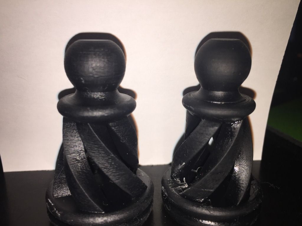
What i cant understand (and maybe its brightness/contrast/hdmi full/slic3r/nanodlp whatever but the different in quality is quite REAL.
Left side = 50 micron Z, 75 micron XY
Right side - 100 micron Z, 75 micron XY
Its night and day
mUVe 3D Admin
Jan 22, 2016, 5:34:01 PM1/22/16
to mUVe 3D Support Group
Ryan,
Best practice is generally going to come down to what the part base size is, and whether or not you're willing to calibrate your machine mechanics to perfection. If you are able to perfectly align the reservoir mounts to a 90 degree against the Z axis, and you're able to keep the build plate a perfect flat to the reservoir bottom. It's just a matter of getting a good reading on Z home when the printer is dry, no resin at all. Then now that I'm thinking about it, it might be good for us to program a new homing routine. Ideally the Z axis would slow down to a low speed during the last few millimeters of the homing process. But it doesn't know where it is until it homes. So maybe we can program a new process where Z homes quickly, lifts by 3-4 mm slowly, and then very slowly returns. This should help make sure Z home is the same each time you command it.
If you want to forego any tedious leveling, just put parts up on stilts and take the resin hit for each print. You're going to need a loss somewhere to make up for the imperfections. It's just a matter of personal preference. The good thing is that, with the new Uber Z especially, our machines tend to stay in-place once they're built. They're terribly strong printers so it usually means less headaches of all kinds ensuring everything is perfect, and it typically lasts a lifetime. Or until an upgrade.
mUVe 3D Support
mUVe 3D Admin
Jan 22, 2016, 5:38:03 PM1/22/16
to mUVe 3D Support Group
Ryan,
Very startling comparison. I think we'll be working on testing all of our stock projector settings as soon as we can. It has been on our list as Hellenicopter brought the point up with us quite some time ago. But yes you can really see the difference. To be honest, the parts on the left look overcured. I think the biggest think you're seeing here is a contrast between settings that are slightly incorrect, versus those that are pretty much looking perfect.
Great job! It looks like the hard work has all been worth it.
mUVe 3D Support
mUVe 3D Admin
Jan 22, 2016, 5:40:18 PM1/22/16
to mUVe 3D Support Group
Cameron,
We're using the ViewSonic projectors. Did you have a specific question about the setup?
In reference to RS-232. Any projector that supports it and has the appropriate port, can use a USB -> RS232 adaptor through nanoDLP so long as there is a code for turning the projector on and off. It's usually listed in the projector instruction manual. That's where we pulled all the ViewSonic codes from that we list on our website currently.
mUVe 3D Support
Ryan LaBarre
Jan 22, 2016, 5:47:54 PM1/22/16
to mUVe 3D Support Group
Thanks dean, i think you are right.. it just comes down to tweaking tweaking tweaking and eventually it hits.
I think its a huge benefit now to have my printer running fairly stock parts. im still using the upgraded steppers and lead screws, but ive toned them down to 100 steps / m vs 400 because of the pitch.
Everything else is now pretty stable builds.
I tell ya, about 3485 times throughout this proces i had a formlabs 2 in my shopping cart, but i wouldnt be any happier with it, except that its PNP. about 2x more expensive to operate as well.
Its funny I hate when things dont work, i get frustrated, kick puppies (kidding) and get pissy all the time, but when it works, and im done tinkering im bored :)
I guess thats why im finishing my Mostly Printed CNC machine :)
Ryan LaBarre
Jan 22, 2016, 11:19:17 PM1/22/16
to mUVe 3D Support Group
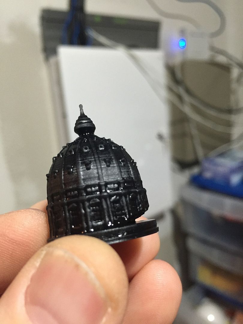
Do you guys/gals notice when printing a hollow part that you get this happening more frequently?
It seems if i use the same settings as a solid part of the same size , and all other settings identical that it ALWAYS peels somewhat like this along where the hollow part begins.
is that just a matter of needing longer cure times for these items? wish that wasnt the case.
mUVe 3D Admin
Jan 26, 2016, 1:50:12 PM1/26/16
to mUVe 3D Support Group
Ryan,
That's usually from not using a mask, or the layer cure time being too low and causing breakage. Since we already know that small detail parts need a bit more cure time, it's probably safe to bump up by .25 or .5 seconds.
Hopefully in the future, we can have software calculate for these differences and create a consistent cure. But for now it's just best to have a tune for small detail parts, and one for large parts.
mUVe 3D Support

Gauthier Quercia
Jan 27, 2016, 11:23:23 AM1/27/16
to mUVe 3D Support Group
hi,
what is "using a mask" and how is it done? may I ask?
thank...
mUVe 3D Admin
Jan 27, 2016, 3:19:46 PM1/27/16
to mUVe 3D Support Group
Gauthier,
We explain mask usage in this other thread: https://groups.google.com/forum/#!topic/muve-3d-support-group/4a97i_iKBkM
It's simply an image that you import into the software you're using, either CW or nanoDLP, which evens the light distribution out of your projector. Both softwares have a place to import the image file. We posted a sample mask file on the post that we linked above if you want to give it a go for yourself.
mUVe 3D Support
João Maia e Silva
Jan 27, 2016, 9:10:59 PM1/27/16
to mUVe 3D Support Group
Hello,
today I made my first successful prints with the new software, very interesting and great evolution for the mUVe!
Some issues and questions:
- I still haven't been able to connect the projector successfully. It is a ViewSonic that came with the mUVe, I had it working with CW, with the serial USB/RS232 and a null-modem adapter. In nanoDLP I've entered the same codes for on/off, but nothing. Any ideas?
- I have been having problems in accessing the RPi through ssh. I'm using my mac's Terminal app. The first time I installed nanoDLP, typing: ssh pi@IP led me in; for some reason I can't recall why, I formatted the SD card and reinstalled the software, same procedure as before. This time, ssh pi@IP, tells me that my RPi is under attack and can't enter it; found out that using: sudo ssh pi@IP, granted me access. This was last friday. Today, it doesn't accept the psw (raspberry) when I try to get in through: sudo ssh pi@IP. I'm really ignorant about this sort of languages. Finding out about "sudo" was a challenge. Could someone direct me to some manual for dummies on this unix language?
- CW has the different sections where to insert custom G code, before, during, after, last layer, etc. How can we tell to pull the plate up after finishing the print and maybe tilt it to drain the resin? I couldn't find a custom G code place for the post-print
- what's the difference between the G code custom fields in the printer profiles: "Execute After Each Layer" and "After Each Layer"?
- is it possible to insert/control the retract speed of the build plate, through G code, as in CW? maybe something like this: M650 D{([[LayerNumber]]<30)*2+3} S{5-(([[LayerNumber]]<30)*4)} R{5-(([[LayerNumber]]<30)*4)}
- Once you upload a SVG, that plate remains associated to a printer profile. If we update/change the printer profile, printing that plate will take into account those changes, right? we don't need to upload the same SVG with the newly changed profile?
- isn't there a way to get a notification after the job is done?
thanks
Matthew Caron
Jan 27, 2016, 9:25:23 PM1/27/16
to mUVe 3D Support Group
I can help on the ssh front.
Firstly, using sudo was the absolute wrong thing to do. Running things as root is a bad idea unless absolutely necessary. I'm not trying to call you out here, I'm just trying to save you hassle in the future, speaking as someone who has been there and done that. Ever remove your home directory? Or blow away the first 64 MB of the second drive your RAID array? Yeah.. not a fun time. ;-)
The reason it said it was under attack is because it was. The first time you went to the machine, it asked you if the key was okay. It then cached the key. When you reinstalled the software on the Pi, you ended up generating a new SSH key. Since it didn't match the cached key, it thought you were the victim of a man in the middle attack. The thing to do here is to remove the cached key, since you know it changed. Do this with:
ssh-keygen -R IP
This will remove the cached key.
The reason sudo worked is because you did it as a new user (root), and the new user hadn't connected to it yet. However, it's best to not do that.
I don't know of any particularly good introductory Unix manual. If you know what command you want, there's always "man", so you can do, for example "man ssh" and it will give you the instructions for that command. But you, or anyone else is welcome to email me about general Unix questions. I generally run Linux, but my wife uses those fruit company machines, so I can always ask her if I don't know the answer. My email is matt at mattcaron.net.
mUVe 3D Admin
Jan 29, 2016, 12:33:59 PM1/29/16
to mUVe 3D Support Group
João,
-The projector should would just as soon as you have the correct speed settings, 115200, and the proper USB->RS232 adaptor entered. If it's still not working once the codes are entered, send us some screenshots of your settings. We might have a bug to report.
-nanoDLP has those same fields for before and after the print, it's on the settings tab. You can enter all your custom pre and post print codes there.
-The "Execute" variety is for running RPi command line commands during a print, you can run any command you wish. Where the other variety is for GCode, Keywords, and math.
-The plates can continue to be used when changes to the profiles are made, so long as you don't change any of the micron settings for X/Y/Z. If you change those, the plates all need to be deleted and uploaded anew. There's a new version out right now that has notifications and better explanation throughout the software.
-There is already a notification when the job is complete, but here you can run a command line command. So you could technically install software to send yourself an email via command line once the print is done. Currently, just leave the browser open and your speakers on. Or plug speakers into the Pi. A bird chirping will be played when the print is complete.
mUVe 3D Support
Ryan LaBarre
Jan 29, 2016, 12:52:03 PM1/29/16
to mUVe 3D Support Group
On that note for the first three days after installing nanodlp on my 100 test prints i couldnt figure out WTF that chirping was... Finally i did and I face palmed.. I was like seriously, did my browser just get hijacked by Chinese bot farmers.
Matthew Caron
Jan 29, 2016, 2:43:08 PM1/29/16
to mUVe 3D Support Group
Other possibilities for notification would be too hook a GPIO up to a relay to control power to a disco ball.
If you're in to not-so subtle notifications. :-)
João Maia e Silva
Feb 1, 2016, 4:35:44 AM2/1/16
to mUVe 3D Support Group
Hi
- regarding projector control, I've attached a screenshot from my settings, 115200, /dev/ttyUSB0 and the respective codes, as show in the muve documentation. Below is an extract from the dmesg I run in terminal, the USB door apparently matches.
[ 5.763300] usbserial: USB Serial support registered for FTDI USB Serial Device
[ 5.763662] ftdi_sio 1-1.4:1.0: FTDI USB Serial Device converter detected
[ 5.763901] usb 1-1.4: Detected FT-X
[ 5.770583] usbcore: registered new interface driver cdc_acm
[ 5.770615] cdc_acm: USB Abstract Control Model driver for USB modems and ISDN adapters
[ 5.820494] usb 1-1.4: FTDI USB Serial Device converter now attached to ttyUSB0
- thanks for all the other explanations
- I heard the bird! really cool!
best
João Maia e Silva
Feb 1, 2016, 8:58:09 AM2/1/16
to mUVe 3D Support Group
the issue I just described was happening on the build 971 of nanoDLP.
I've just uploaded it, now Build 977, but still can't control the projector, with the same settings
mUVe 3D Admin
Feb 1, 2016, 1:53:37 PM2/1/16
to mUVe 3D Support Group
It appears we are needing to make a change to nanoDLP. Please give us a few hours to test and try to push a new release. At that time, I'll post the codes as well. Then everyone can just copy and paste.
mUVe 3D Support
mUVe 3D Admin
Feb 1, 2016, 3:45:14 PM2/1/16
to mUVe 3D Support Group
Ok, please download the latest version of nanoDLP and then use the following commands:
-First, set the connection type to USB/Serial - Binary, Speed 115200
Projector On: \x06\x14\x00\x04\x00\x34\x11\x00\x00\x5D
Projector Off: \x06\x14\x00\x04\x00\x34\x11\x01\x00\x5E
That should do the trick! Thanks again to Shahin at nanoDLP for a quick addition/fix!
mUVe 3D Support
João Maia e Silva
Feb 2, 2016, 5:02:22 AM2/2/16
to mUVe 3D Support Group
Ok, just got it working!
best

Elliot McAllister
May 11, 2016, 12:23:49 PM5/11/16
to mUVe 3D Support Group
I did the same thing?! What - who's calling me on Skype!?
mUVe 3D Admin
May 11, 2016, 12:59:23 PM5/11/16
to mUVe 3D Support Group
Elliot,
I'm sorry, we're not sure what you're saying here. We don't see you in the previous posts and your description doesn't give us much to work with. Could you explain what the problem you're experiencing is?
We're not sure who's calling you on Skype, but it's definitely not our organization.
Best of luck.
mUVe 3D Support
Elliot McAllister
May 11, 2016, 1:27:26 PM5/11/16
to mUVe 3D Support Group
Hi Dean-
I was reading though this to try and diagnose a delamination I am having during the first prints with the nano. I thought it was really funny that I had heard the bird chirping and for the life of me could not figure out why on earth someone from Skype was calling me - esp. since it was not loaded. Took me 4-5 prints to know this was the "complete" signal from the printer! I thought the comment would be added to Ryan's original post - not the end of the thread.
Apologies for the confusion.
My issues seem to be the same as Ryan's. I have what I think are excessively long cure times as compared to the CW. But could be from the larger print pieces I am making. (screenshot posted) Bed dim: 132x67mm
1. -So I have the following settings saved and double checked the printer is running with this profile.
2. -I did not have a mask set up on the original print but will add it for the next one. (the general one set-up by mUVe)
3. -I attached pictures of the failed prints by delamination. Reviewing them there are a few apparent items:
-Overcure on the initial layers - areas are filled in that should not be, and some areas are much to large. The settings for initial layers are 50 sec, 100um thickness, well mixed SubG+ red. (see pics)
-As I have increased the inital cure time, the parts stick for longer but eventually de-lam (now at about 20% through the print)
-maybe they are starting to delam because of the thickness and repeated movements - thinking about reducing the normal layers time to 10 sec as per Ryan's findings - different projector I know)
4. I checked the Pi, I have the correct HMDI settings - but I did notice a segment where we might be able to flip the image outside of projector control- anyone tried this?
For the next print:
1. slow speed section 100mm/sec
2. drain the vat and check platform level as well as home height (I have the end stop so it cuts the motor when the platform actually has a little bit of pressure on the bottom) It could be too much and actually causes the inital layers to be thinner because of flex in the gantry.
3. Check the brightness and contrast settings on the projector - but it is set up as previous.
4. reduce the overall amount of resin in the vat.
Thanks guys for checking in!
Elliot McAllister
May 11, 2016, 5:40:35 PM5/11/16
to mUVe 3D Support Group
If anyone else is fooling around with this:
Just like to get some feedback on the Viewsonic Projector settings:
I found the brightness and contrast settings and adjusted as per InTheLab thread above: Currently set the brightness to 0 and contrast to 50. (Got a little worried setting the brightness to 0 when the image was fading to black).
Interested to see if anyone has played with the color filters:
There is an option to set RGB, and then also blue offset, seems like by description we would want to play with this filter - but without a spectrum analysis there is no way to tell.
(Dean - what color scheme was used for the viewsonic projection output spectrum readings?
Thanks all-
Everyone who helps adds to the knowledge base - questions help others!
Elliot McAllister
May 11, 2016, 6:20:18 PM5/11/16
to mUVe 3D Support Group
Just to continue, I'm wondering if peeps have played around with the other settings - or -and I'm completely fine with this, just a standard setting for the color profile:
Currently Using:
Color Mode:
User 1
reference Mode: "Gaming" scheme from the standard choices include: brightest, dynamic PC, PC, Movie, ViewMatch, dynamic movie and gaming. (I did not set this up when in CW, whatever was default seemed to work)
Can alter Brightness and Contrast for all choices:
Brilliant color is "ON"
In Advanced:
Noise reduction: 8 from setting range of 1-16
Color Choice: Using T1 (out of T1-T8) currently but have the option to tune this one for more UV light vs full spectrum.
Within Temperatures (obviously we can change the RGB spectrum) As well as designate the offsets for RGB -
Seems like toning down the filters for Red and Green would allow better projection for the 405nm UV....but looking to see if anyone did this already.
Thanks!
mUVe 3D Admin
May 12, 2016, 11:14:25 AM5/12/16
to mUVe 3D Support Group
Elliot,
No blue offset, no filters, no anything other than setting brightness and contrast both to 50. Setting brightness to 0 is going to cause long layer cure times, higher than 50 and the black areas might start to turn grey. Which will cause curing in the dark regions. Make sure eco mode is off as well. No noise reduction. This is a digital signal so noise shouldn't be an issue unless you're using poor cords or something bad is happening that shouldn't be. Once all the settings are set, flip the projection image so that it is reversed. Once all that is done it should be left alone and also make sure that you make all of the changes while the RPi is plugged into the HDMI port, and you have the HDMI input selected as what is currently being displayed.
mUVe 3D Support
Elliot McAllister
May 12, 2016, 3:38:47 PM5/12/16
to mUVe 3D Support Group
HI guys, thanks for the tip. I understand the above.
Quick Question: What is the base start projector setting everyone is using? User 1 or Gaming, etc?
Thanks
I still seem to be getting delamination part way through the bigger prints the area is probably close to 30% of the 136x76mm bed dimensions.
mUVe 3D Admin
May 12, 2016, 4:05:47 PM5/12/16
to mUVe 3D Support Group
Elliot,
As soon as you change any of the video settings it should no longer be a preset, rather "User" instead. So there isn't a preset, and definitely don't change the color settings as those projectors are perfect out of the box as that'll break the factory calibration. They use expensive tools that we don't have, and several companies have tested them to have really great accuracy out of the box. So adjustment of anything other than brightness and contrast isn't needed.
Delamination meaning the part breaks into two? This usually means you're undercuring and need to increase your cure times. That or the part is too fragile and needs support to help hold it together.
mUVe 3D Support
Elliot McAllister
May 12, 2016, 4:50:43 PM5/12/16
to mUVe 3D Support Group
OK Thanks Dean!
I guess I was just getting finicky with the settings because it wasn't the same as the previous ones in CW. Originally, I had just used it out of the box - no selection. I'll do a factory reset and then change the settings you listed. I did install the mask within the program.
It's a weird problem. Basically, the part delaminates from the base layer. I can't tell yet which of the following is occurring:
1. Under-cured base layers - (though looking at the base layer it is definitely over-cured and should be solid) (settings are 100um speed, 100 um layer height, 50-52 seconds cure time)
2. Over-cured normal layers - which are stuck too well to the FEP. I haven't used the FEP too much so I don't think that it is worn out and causing this (8.5 seconds cure time same as above except after layer 30 it moves in speed upto 200 um)
3. Possibility: if it is #1, then the part falls to floor and is subsequently polymerized to the FEP during the rest of the run. I can't tell when the delamination happens because it doesn't raise high enough from the vat to view.
4. I did have a part separation when I moved the normal layers to 6.5 sec exposure - but there was also delamination on the base layer. I think I should go to 54 or 56 seconds for the first 2-3 layers and try again with 8 or 7.5 sec exposure time.
mUVe 3D Admin
May 13, 2016, 12:14:50 PM5/13/16
to mUVe 3D Support Group
Elliot,
FEP doesn't wear out chemically. You'll notice more and more scratches over time, those scratches can cause excess adhesion to the FEP. But that's about it.
Based on our starting profiles that we provide in nanoDLP. 6.5 seconds is not enough layer cure time for the build area you're using. For your build area we're using about 9 seconds as our starting place. It sounds like through projector settings and changing profiles you've gotten a bit off-track.
We think it's probably best you start over with defaults everywhere. Use the default nanoDLP SubSF profile for the X/Y microns that is closest to your actual measurements, clone it with the new X/Y microns entered, and start uploading parts anew. We also notice that you're talking about "100um" speed settings, etc. these speed settings only apply to RPi connected motors. Changing them in your setup will have no impact. You change speed settings through the GCode as instructed in the documentation.
mUVe 3D Support
It is loading more messages.
0 new messages