From test board to prototype
397 views
Skip to first unread message

Marc Rechté
Jun 13, 2023, 12:10:13 PM6/13/23
to MPF Users
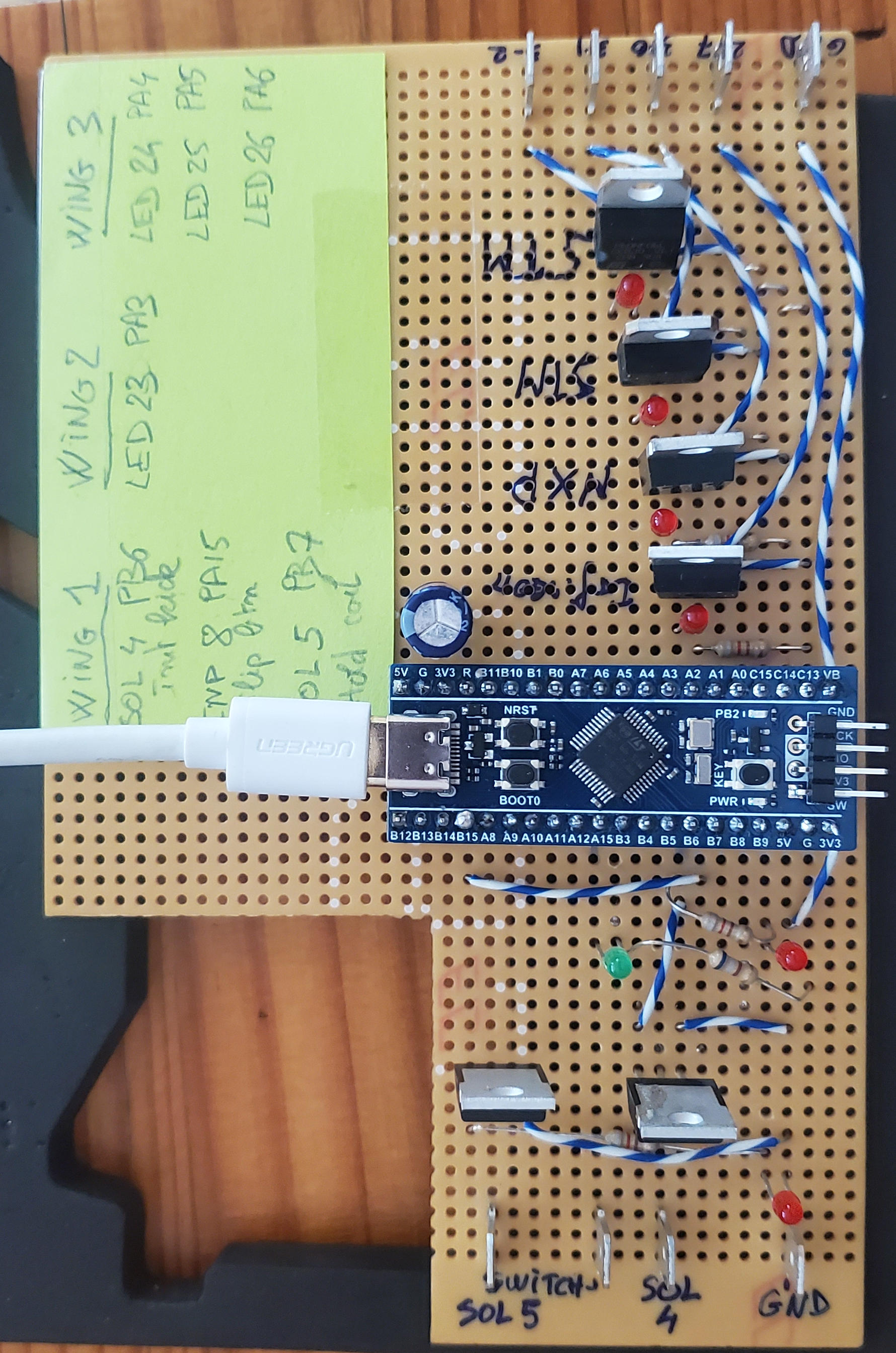
Test board:
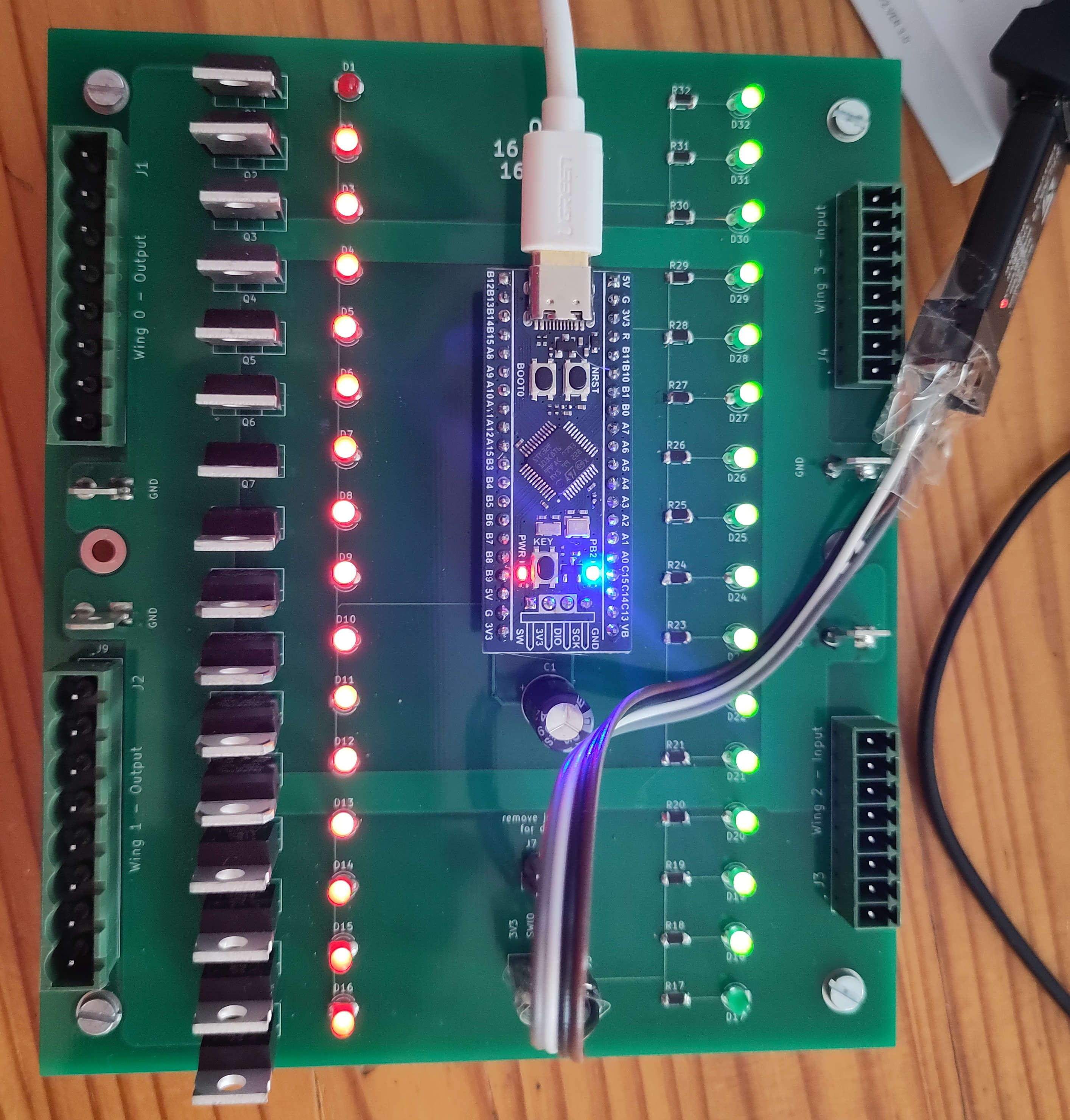
To prototype PCB:


Dan - aka BorgDog
Jun 16, 2023, 5:58:54 PM6/16/23
to MPF Users
looking good (from my amateurs' eyes anyway). let us know how it works out.

cobra18t
Jun 17, 2023, 4:09:35 PM6/17/23
to MPF Users
Very nice! On the next rev, I would add pull-down resistors to the gates of the FETs. Also, I see current limiting resistors on D17-D32 but not on D1-D16. Are there other components on the bottom side?

OPP
Jul 5, 2023, 1:36:52 PM7/5/23
to MPF Users
Take this with a grain of salt, but doing a quick look at the data sheet, maximum source/sink current for the whole STM32F103x8 (Sigma IINJ is +/-25mA, Table 7, page 37). https://www.st.com/resource/en/datasheet/stm32f103c8.pdf
Because of that, I would beef up the resistors on the source side. Right now the maximum source current is around 64mA. Change the 820 ohm resistors to higher values. I would choose something like 3.3 Kohm resistors. That would keep you well below the 25mA maximum source if you start driving all of your coils at once. I'd also use the same 3.3K resistors on the inputs side because why use 2 values of resistors when just one will work. Makes for easier populating of the board, less different parts, blah, blah, blah.
Sometimes people add a couple extra pins to connectors to have blocked pins to insure that the wrong cable can't be plugged into the wrong position. I would separate my high voltage grounds (connected to the source of the NChan MOSFETs) from my processor/logic grounds. If you want to connect them on the board, use either a jumper or solder bridge. (Of course, then you will constantly be worried that people aren't correctly attaching their grounds together properly.) Looks good!
-H
Marc Rechté
Jul 8, 2023, 9:57:47 AM7/8/23
to MPF Users
I checked the MCU datasheet table 7, what I can read is that total sink current should not exceed 150mA in total, 25mA per pin.
Regarding grounds, I wonder how it would be possible to drive FETs if their ground are not connected to MCU ground.
Regarding grounds, I wonder how it would be possible to drive FETs if their ground are not connected to MCU ground.
OPP
Jul 13, 2023, 7:59:06 PM7/13/23
to MPF Users
Re-reading the spec sheet (and all the notes this time) I believe you are right. Maximum 150mA for sourced/sunk current with 25mA max for each I/O pin. The other parameters are for injected current which occurs with inputs above VDD or below VSS. My bad. I'd still choose 1 resistor value to make population even easier. It doesn't take much current to make an LED bright enough for debug purposes.
The point on the grounds is about separating the logic/processor grounds from the high voltage grounds. The coils are probably driven from a high voltage power supply. The processor and logic grounds are probably from a low voltage power supply. The grounds from both of these power supplies need to be tied together somewhere. It is best to do that near the power supplies but it can be on the board. I'm guessing the blue pill is being powered from the USB port. All of the grounds going to the switch inputs should be attached to a gnd pin that is from the blue pill. Then those big ground spades should go to the high voltage supply ground. It is tough to know how all the grounds are connected without seeing the gerbers.
Let's say a couple of coils are firing. Each one is maybe 10ish amps to be conservative (48V with 4.7 ohms for a red williams coil). That means 20 Amps is zooming through the board to the ground spades. All that current needs to go back to the ground of the 48V power supply. As it goes zooming across the board, the resistance of the trace causes the ground reference to be a higher voltage. This could cause ground bounce on the board. It probably won't matter, but by separating the grounds cleanly it can't happen.
If the board connects the gnd pin(s) from the blue pill to some pin that you can use to feed the switch closures, and then another gnd pin connects directly to big ground pin traces, everything will work perfectly. If all the grounds are connected together, it will still probably work perfect, but it isn't ideal.
Sorry for such a pitiful long winded message, but I find it difficult to explain grounds and how they should be separated and connected clearly.
-H
Marc Rechté
Sep 27, 2023, 9:38:00 AM9/27/23
to MPF Users
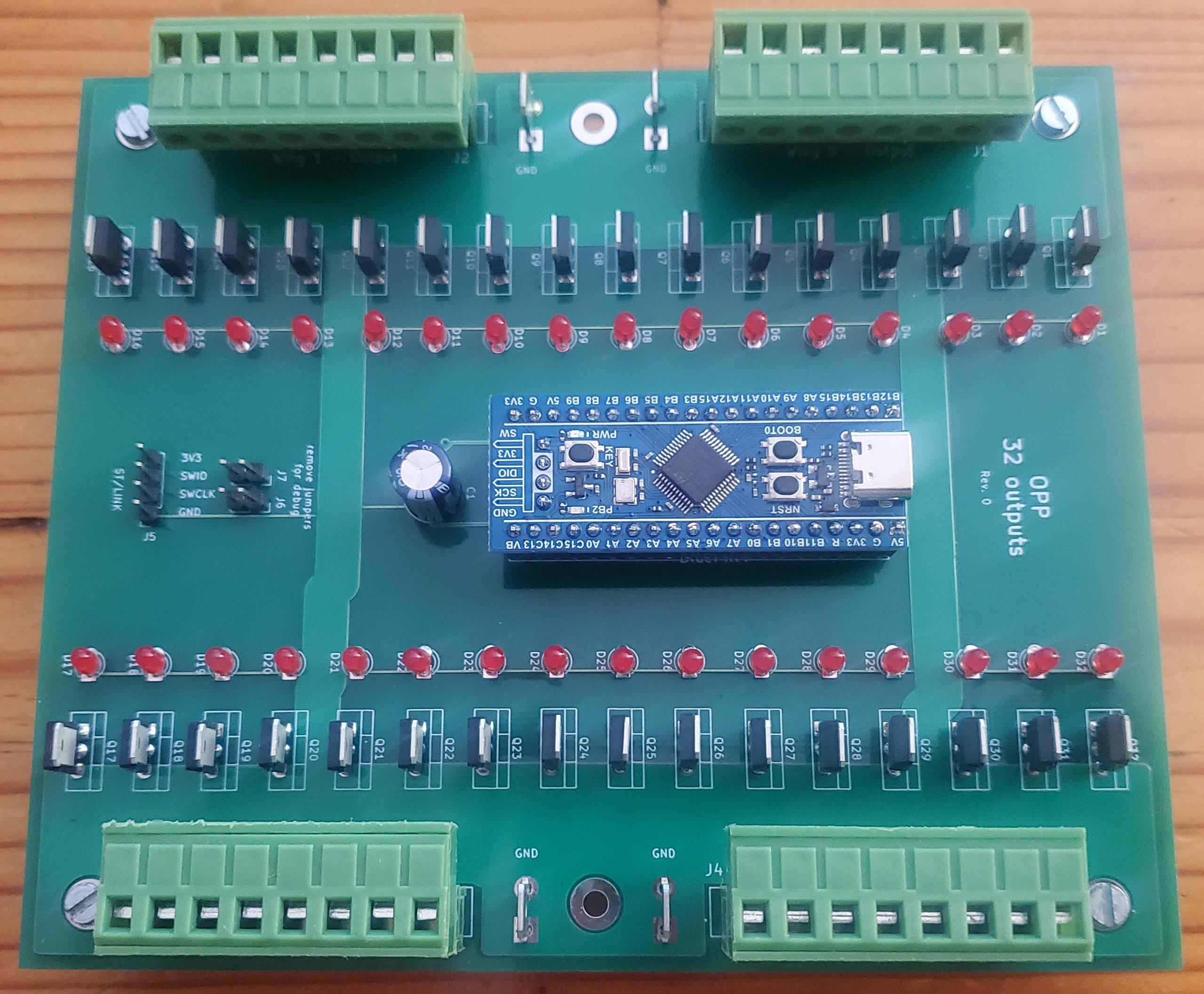
Sister card is ready: 32 outputs
Hugh R Spahr
Sep 28, 2023, 7:35:29 AM9/28/23
to mpf-...@googlegroups.com
Nice job. I believe that you should be able to drive the board without changes through MPF as an OPP board with four incandescent wing boards. (I.e. that should allow on/off of these MOSFETs). Here is the applicable MPF documentation where they are called lights. https://missionpinball.org/hardware/opp/lights/. Just note that this won't make use of the "real time" aspects of the firmware. It doesn't support things like receiving an input bit and firing a coil for a certain number of ms. The firmware could be extended to support this, but MPF would also need to send an external trigger to fire the coil. That may be useful for driving something like a bingo machine or even a large EM style backbox where real time performance for scoring isn't required. I don't know if this would work well for things like pops or slingshots because the input would first need to be read by the host (MPF) then a command would need to be sent to this board to trigger a coil cycle. (Maybe it would be fast enough, but it would be very system/host computer speed dependent) The counter argument to that is that I've seen MPF send multiple messages in a second, and if it can rcv/xmt commands in a low number of ms, it should work well.
Nice job on the board!
-H
--
You received this message because you are subscribed to a topic in the Google Groups "MPF Users" group.
To unsubscribe from this topic, visit https://groups.google.com/d/topic/mpf-users/fBTue_cSHhU/unsubscribe.
To unsubscribe from this group and all its topics, send an email to mpf-users+...@googlegroups.com.
To view this discussion on the web visit https://groups.google.com/d/msgid/mpf-users/f54008a3-d0c6-42b5-8f25-5ed47a9a4221n%40googlegroups.com.
Marc Rechté
Sep 28, 2023, 9:30:44 AM9/28/23
to MPF Users
Thanks for your support.
Yes I assume MFP won't have to be patched for this card. However for opp16o16i, it will require to introduce a new wing type (WING_SOL_8).
I just published the kicad files (revision 1).
Marc
Hugh R Spahr
Sep 28, 2023, 7:11:40 PM9/28/23
to mpf-...@googlegroups.com
Isn't an OPP 16o16i simply the 4 solenoid wing board configuration? Keep all of the high current stuff on the one side of the PCB through routing of the MOSFETs to one side of a card. The PCBs seem to be relatively large so the routing of the drive/input signals to a banks should be easy.
--
You received this message because you are subscribed to a topic in the Google Groups "MPF Users" group.
To unsubscribe from this topic, visit https://groups.google.com/d/topic/mpf-users/fBTue_cSHhU/unsubscribe.
To unsubscribe from this group and all its topics, send an email to mpf-users+...@googlegroups.com.
To view this discussion on the web visit https://groups.google.com/d/msgid/mpf-users/8a560bdc-e803-4bc4-9da5-e80eaab00ea5n%40googlegroups.com.
Thomas Fulenwider
Sep 28, 2023, 9:53:32 PM9/28/23
to mpf-...@googlegroups.com
I think he might have gone with two wings of inputs and two wings of outputs as opposed to conforming to the existing wing options. If you want to do a board spin, you can do 4 solenoid wings as OPP suggests and still get 16 in and 16 out.
To view this discussion on the web visit https://groups.google.com/d/msgid/mpf-users/CAD9bh00o91SB9nO07RjPauw9_c%2BVQGr4e6-EMb%2BtMWMRPVoDUw%40mail.gmail.com.
Hugh R Spahr
Sep 29, 2023, 7:12:53 AM9/29/23
to mpf-...@googlegroups.com
Just saying if you do it as 4 sol wings, there are no changes needed for MPF and no changes for firmware. Since a PCB is being created, it is pretty simple to route the signals to the desired position on the PCB.
The 32 solenoids would need changes because there is only an array of 16 solenoid objects in the firmware if you want to control them as solenoids (i.e. fire for a 32 ms pulse). There is also the issue of the non-volatile configuration of the solenoid only has 16 configuration positions. I don't really understand what the use case is, so it is tough to say exactly what changes would be necessary.
-H
To view this discussion on the web visit https://groups.google.com/d/msgid/mpf-users/CABMT2j3n%3DyT_uz1WP5vKvy7OPSOVVoWwo7f80-bCCkHJF4-9Yg%40mail.gmail.com.

Marc Rechté
Sep 29, 2023, 1:10:18 PM9/29/23
to Abridged recipients
WING_SOL makes the assumption that 4 lines are outputs and 4 lines inputs. In case where you have many solenoids that are software driven only, it is a waste of I/O lines.
In fact WING_SOL_8 is applicable to both opp32o and opp16o16i, providing you do not have more than 2 wings of this type.
It becomes possible to use opp32o to drive 16 lamps + 16 solenoids.
Firmware has been updated accordingly including flash config saving.
Another concern I have regarding MPF is the way cards are identified through their device name (/dev/tty...), and not their seial number, which would make configuration easier than writing obscure udev rules...
Télécharger TypeApp pour Android
cobra18t
Sep 29, 2023, 1:25:22 PM9/29/23
to MPF Users
MPF can identify the cards by their serial number. That is exactly what I do for CobraPin. You have to identify which ports you use, but it does not matter which port each of the cards grab. No special udev rules.
A snippet from: https://missionpinball.org/hardware/opp/cobrapin/
#config_version=5
#CobraPin Example Config
hardware:
platform: opp
driverboards: gen2
opp:
#Use the USB ports defined by your OS for the two STM32 boards
ports: /dev/ttyACM0, /dev/ttyACM1
#USING SERIAL NUMBERS INSTEAD OF CHAINS
# Board 0 has serial number 0, Board 1 has serial number 1.
# This is convenient if your OS tends to reassign the serial port.
# MPF will automatically address the correct board even if the ports
# are swapped.
#For multiple CobraPin boards in a game, you will either have to give
# the STM32 boards on the second CobraPin board new serial numbers
# (10 and 11 are suggested for the 2nd board since 2 is used by the
# CobraPin Xpansion Board)
# <OR> Use the chains section to assign a port to a board number.
# Mixing these up could cause blown FETs, coils, and fuses. Proceed
# with caution. Test without coil power and use the yellow coil LEDs
# for feedback.
#chains:
#0: /dev/ttyACM0
#1: /dev/ttyACM1
Marc Rechté
Sep 29, 2023, 1:57:45 PM9/29/23
to Abridged recipients
+1. Thanks
Télécharger TypeApp pour Android
Marc Rechté
Dec 2, 2023, 10:36:00 AM12/2/23
to MPF Users
7 cards are ready, so is basic MPF game config.


Hugh R Spahr
Dec 2, 2023, 4:54:14 PM12/2/23
to mpf-...@googlegroups.com
Fantastic. This will be a great test to see if you can drive semi-realtime behavior over the USB bus. My whole fear of these types of cards would be that the USB would hamper the real time response. That's why every solenoid needed to be driven from an input or a switch matrix on the same card. While pinball needs real time performance, it is very slow real time performance. I assume you are just extending the host processor control so setting a bit causes a particular strobe length for the solenoid.
I'm really excited about the possibility of this. I think either Fast or PROC did not have that restriction so maybe my fears were always unfounded. Congratulations on getting this build done. I look forward to hearing further progress on it.
-H
--
You received this message because you are subscribed to a topic in the Google Groups "MPF Users" group.
To unsubscribe from this topic, visit https://groups.google.com/d/topic/mpf-users/fBTue_cSHhU/unsubscribe.
To unsubscribe from this group and all its topics, send an email to mpf-users+...@googlegroups.com.
To view this discussion on the web visit https://groups.google.com/d/msgid/mpf-users/9d1c581b-0978-43f6-86c4-5543b3ed3aefn%40googlegroups.com.
Marc Rechté
Dec 22, 2023, 4:53:17 PM12/22/23
to MPF Users
cobra18t
Dec 22, 2023, 5:01:35 PM12/22/23
to MPF Users
The video is private. Was that intentional?
On Friday, December 22, 2023 at 1:53:17 PM UTC-8 mre...@gmail.com wrote:
https://youtu.be/wkdzc2ZNsSM?si=XHsknXfjtPYt3-jE
Marc Rechté
Dec 22, 2023, 5:17:13 PM12/22/23
to Abridged recipients
Should be ok now.
Télécharger TypeApp pour Android
Marc Rechté
Feb 22, 2024, 4:19:55 AM2/22/24
to MPF Users
Cabling is going on. So far light box and play field are done.


Marc Rechté
Sep 16, 2024, 3:28:45 AM9/16/24
to MPF Users
I am pleased to announce release 2.4.255.9 of OPP fork (should be compatible with OPP). Feedback appreciated.
cobra18t
Sep 17, 2024, 4:36:11 PM9/17/24
to MPF Users
That is fantastic, Marc. Do you have any intention of absorbing the OPP 3.0.0.0 changes into your fork? The USB bootloader from that version is a really good addition.
Conversely, do you know if OPP will incorporate your changes back into the main branch?
Marc Rechté
Sep 19, 2024, 12:04:58 PM9/19/24
to MPF Users
Yes I hope to include Booty in the next release. Regarding OPP, I'll let Hugh reply :)

David
Sep 22, 2024, 6:09:25 PM9/22/24
to mpf-...@googlegroups.com
Hi Marc, great to see people sharing their work on OPP. More flexibility
and options for home brewers is really good. I had a quick look at your
repo on the weekend and offer a few comments and questions. As usual
feel free to ignore :)
You don't mention switch matrix in your write up, but I would think you
could support it. A user could just not install the input leds as they
would provide no use in a matrix setup.
To me it's an odd mix to use surface mount resistors and other through
hole components. I'm a dinosaur and dislike surface mount and so would
use all through hole - easier for home assembly and board space not
really an issue.
The sol8 wing is most interesting. With the sol8 wing have you tested
latency for things like pop bumpers and slings? Is the processing fast
enough to do away with the direct switch drives that are typically used.
I know this will depend on usb speed / host computer speed / depth of
code etc, but wonder if you have a feel for it? If it is fast enough
this is great as a single STM might then be capable of run a simple
machine as you could do 64 switch matrix, a neo led string and 16
solenoids (2 x sol8) or 12 solenoids (1 x sol8 + 1 x sol). The use of
sol8 would lose the ability to test in whiteboard mode but the increased
density would be very handy.
The way you are driving the mosfets I think needs to be improved. You
want a pull down resistor between gate and ground to ensure it shuts off
reliably and quickly upon loss of the gate signal from the STM this is
usually done with a 10k resistor. It's also very typical to have a
series resistor (100 ohms) between the STM signal and the gate of the
mosfet, this is more for high frequency effects, but I think is
considered good practice.
Thanks for posting and sharing your work, cheers, David.
On 16/09/2024 5:28 pm, Marc Rechté wrote:
> I am pleased to announce release 2.4.255.9 of OPP fork (should be
> compatible with OPP). Feedback appreciated.
> https://gitlab.com/mrechte/open-pinball-project
--
This email has been checked for viruses by AVG antivirus software.
www.avg.com
and options for home brewers is really good. I had a quick look at your
repo on the weekend and offer a few comments and questions. As usual
feel free to ignore :)
You don't mention switch matrix in your write up, but I would think you
could support it. A user could just not install the input leds as they
would provide no use in a matrix setup.
To me it's an odd mix to use surface mount resistors and other through
hole components. I'm a dinosaur and dislike surface mount and so would
use all through hole - easier for home assembly and board space not
really an issue.
The sol8 wing is most interesting. With the sol8 wing have you tested
latency for things like pop bumpers and slings? Is the processing fast
enough to do away with the direct switch drives that are typically used.
I know this will depend on usb speed / host computer speed / depth of
code etc, but wonder if you have a feel for it? If it is fast enough
this is great as a single STM might then be capable of run a simple
machine as you could do 64 switch matrix, a neo led string and 16
solenoids (2 x sol8) or 12 solenoids (1 x sol8 + 1 x sol). The use of
sol8 would lose the ability to test in whiteboard mode but the increased
density would be very handy.
The way you are driving the mosfets I think needs to be improved. You
want a pull down resistor between gate and ground to ensure it shuts off
reliably and quickly upon loss of the gate signal from the STM this is
usually done with a 10k resistor. It's also very typical to have a
series resistor (100 ohms) between the STM signal and the gate of the
mosfet, this is more for high frequency effects, but I think is
considered good practice.
Thanks for posting and sharing your work, cheers, David.
On 16/09/2024 5:28 pm, Marc Rechté wrote:
> I am pleased to announce release 2.4.255.9 of OPP fork (should be
> compatible with OPP). Feedback appreciated.
> https://gitlab.com/mrechte/open-pinball-project
This email has been checked for viruses by AVG antivirus software.
www.avg.com
Marc Rechté
Sep 24, 2024, 12:21:45 PM9/24/24
to MPF Users
Hello David. Thanks a lot for your feedback.
Le 23/09/2024 à 00:09, David a écrit :
![]()
Le 23/09/2024 à 00:09, David a écrit :
Hi Marc, great to see people sharing their work on OPP. More flexibility and options for home brewers is really good. I had a quick look at your repo on the weekend and offer a few comments and questions. As usual feel free to ignore :)
You don't mention switch matrix in your write up, but I would think you could support it. A user could just not install the input leds as they would provide no use in a matrix setup.
Regarding switch matrix, the code is there, but I have not tested
whether my changes brought a regression. On top of that, if I understand
correctly, wing 2 would be an output and wing 3 an input in that setup.
This would not match OPP16o16i board design which assumes wing 2 and 3
are both inputs. This would have to be tested with a Cobrapin board.
To me it's an odd mix to use surface mount resistors and other through hole components. I'm a dinosaur and dislike surface mount and so would use all through hole - easier for home assembly and board space not really an issue.
Well this kind of SMC resistors are not too hard to solder, just a
matter of disposing of tweezers like the one on attached pic. On the
other hand I wanted transistors to be easy to replace.
The sol8 wing is most interesting. With the sol8 wing have you tested latency for things like pop bumpers and slings? Is the processing fast enough to do away with the direct switch drives that are typically used.
SOL_8 may be triggered directly by the MCU assigning an input pin on the
*same* board, using the "Set Solenoid Input, 0x17" command. Actually
this is how MPF configure solenoids.
I know this will depend on usb speed / host computer speed / depth of code etc, but wonder if you have a feel for it? If it is fast enough this is great as a single STM might then be capable of run a simple machine as you could do 64 switch matrix, a neo led string and 16 solenoids (2 x sol8) or 12 solenoids (1 x sol8 + 1 x sol). The use of sol8 would lose the ability to test in whiteboard mode but the increased density would be very handy.
Not clear what you mean by "test in whiteboard mode". In my setup (RPi 3
B+), I have 2 boards configured with 2 x SOL_8 wings each. Using more
than 2 SOL_8 wings would make sense for solenoids that can be driven by
MPF (using "Kick Solenoids, 0x07" command), but for sure not for
bumpers, flippers which requires a very short latency between the
command and the coil activation.
The way you are driving the mosfets I think needs to be improved. You want a pull down resistor between gate and ground to ensure it shuts off reliably and quickly upon loss of the gate signal from the STM this is usually done with a 10k resistor. It's also very typical to have a series resistor (100 ohms) between the STM signal and the gate of the mosfet, this is more for high frequency effects, but I think is considered good practice.
Well, the MCU pin is configured as push-pull, so when it is set low, it
pulls the gate towards the ground. On an OPP32o, a state of the art
setup would require 32x3 resistors... I have equipped a Fast Draw EM
with those boards (7 of them), it has been working well for over 6
months (over 1000 plays).
Thanks for posting and sharing your work, cheers, David.
Best regards. Marc
On 16/09/2024 5:28 pm, Marc Rechté wrote:I am pleased to announce release 2.4.255.9 of OPP fork (should be compatible with OPP). Feedback appreciated.
https://gitlab.com/mrechte/open-pinball-project
Marc Rechté
Sep 24, 2024, 12:23:23 PM9/24/24
to MPF Users

Hugh R Spahr
Oct 14, 2024, 6:09:01 PM10/14/24
to mpf-...@googlegroups.com
Sorry for being so slow at getting back. I saw this nearly a month ago, and it has taken me this much time to get around to answering it. I thought that when the kids went to college I would have a plethora of time, but it just turns out that work ends up sucking that extra time that you were expecting to have. (Work decided to put me on a couple of projects to "save" them which involved lots of extra hours). If I have neglected sending any of you a response email, I apologize. (I wanted to congratulate Cobra on picking up the bulk cap board, but never got around to it. Cobra, I know that I owe you an email.)
Enough of my personal story. Congratulations on getting this completed Marc. It always takes a ton of work and the only one that can complete such an endeavor is somebody very passionate about the hobby. I have seen a few of your videos and it looks great.
The input switch matrix is hard coded for ports 2 and 3 in the firmware. (It will not allow these wings to be located at other wing positions). This was to minimize the number of possibilities so the firmware could be cleaner, and made the most sense since certain wings couldn't be used because of hardware limitations (mostly the driving of Neopixel bits on a certain pin).
The original OPP hardware was based on the 8 bit HCS08 processor and the communication was a ring based serial at 19.2 Kbps. That scheme was certainly not fast enough to have switches separate from the solenoids and triggering them remotely. Second version of OPP hardware was PSOC4200 processor (I think), and that once again used a token based communication ring at 115.2 Kbps. That processor of course went the way of the dinosaur and so here we are at the STM32F103 based version of OPP. During the transition from PSOC to STM, I added switch matrix support. This was the first time that I really started to understand how slow (in processor time) pinball really is. I replaced a Bally pinball machine hardware with OPP hardware, and in that case, a switch matrix input is used to fire the solenoids. Before this point, I probably would have guessed that it would not be fast enough. Taking the Addams family switch matrix for example (https://homepinballrepair.com/wp-content/uploads/2019/12/Addams-Family-Switch-Matrix.jpg)...it reads 500 time/s or every 2ms. (Note switch inputs for things like Upper Left Jet, Left slingshot, etc) Of course, worst case, you will have to read the whole switch matrix before getting to the correct column and there are 8 columns, so it might take up to 16ms to recognize a switch input. Then say you can drive the solenoid immediately. With the current version of the hardware (STM32) and using point to point USB, it should be relatively easy to reach this latency. Now there is a whole lot of other things that factor into it (such as speed of MPF polling, amount of queued packets, etc) but it should work. To make it more clear, I think that having an input on one OPP board, then calling a solenoid kick on a different OPP board should work with the latest hardware. This goes back to the fact that I just didn't understand how mechanically or physically slow pinball really is. (In my real job people say that need real time performance. I always have to ask them what that means to them. When triggering a light source, it meant < 1us delay, with pinball, it seems 16 ms can be considered real time enough)
With the OPP firmware, Marc has found a few bugs that could be addressed in an updated version. (Thanks Marc for finding these.) None of the bugs affect the operation code, so they are all really low priority. At some point I will update the code to address them, but since they can't cause any issues, it is certainly not high on my list of priorities.
I doubt if I will merge Marc's code back into OPP unless a whole bunch of people ask me to do it. If somebody asks me for a new feature and I'm modifying the code and need to run all the regression tests again, I might do it, but, barring that, probably not. If somebody said, hey Hugh, could you do this and it tickled my fancy, I would probably do it.
On jumping to using Booty. (3.0?). It would be great if Marc would move to that. It drove me insane that when I moved from PSOC to STM, I lost the bootloader. (All other versions had bootloaders so cards could be updated in situ). I knew Marc was making updates at the same time I was doing the bootloader, but we both had our own schedules. It is up to him if he wants to spend the time.
This response is already too long. Congratulations again Marc for finishing this hardware. I see it especially useful for driving things like score reels on old EMs. You would have had to throw another couple of boards in there to drive them, where a 32 bit solenoid card would make that much cleaner. Nice! Good luck.
-H
--
You received this message because you are subscribed to a topic in the Google Groups "MPF Users" group.
To unsubscribe from this topic, visit https://groups.google.com/d/topic/mpf-users/fBTue_cSHhU/unsubscribe.
To unsubscribe from this group and all its topics, send an email to mpf-users+...@googlegroups.com.
To view this discussion on the web visit https://groups.google.com/d/msgid/mpf-users/3daa6d18-ca33-4f79-b7fc-3be8d624368dn%40googlegroups.com.
David
Nov 23, 2024, 5:07:07 PM11/23/24
to mpf-...@googlegroups.com, openpinba...@gmail.com
Hi Hugh, I don't know if anyone else
has given feedback on this, but here's my 2 cents worth. In
summary I would love to see the sol_8 wing integrated into the
main body of OPP, here's why.
With the speed of STM32 processors and an understanding of the "real time" needs of pinball it is entirely possible and practical to use a switch from within a matrix to drive an MPF auto fire coil such as a sling or pop bumper. This in turn frees up the need for direct drive switch inputs in the existing (4 way) solenoid wings. I understand why direct switches were initially used / needed, but now we can make better use of the available processor I/O pins. (I have tested switches from within a matrix driving an auto fire coils on the same STM32 and it works fine. I was going to measure the timing with a logic analyser, but it is clearly fast enough just by visual observation.)
So if the WING_SOL_8, and I guess a WING_SOL_NEO_8, was implemented then a single STM32 could have an 8x8 switch matrix, drive 256 neopixels and 15 solenoids. This would be ideal for;
- EM re-themes where the back box / score reels are being discarded
- EM wedge heads because they only drive four score reels
- early Solid State re codes to extend or replace a failed control system
- Williams Sys3-6 had 16 solenoids + 6 special solenoids, but 5 were for sound, 1 for coin lockout and most games had unused solenoids
- Bally / Stern had 15 instantaneous solenoids
- GTB had 8 solenoids in sys1, 9 in sys80 and 25 in sys3
- single level original home brews
- EM style home brew arcade games - like Ice Cold Beer etc
In general, for a "typical" pin, this config supports two slings, one ball serve, two (maybe one) flipper enable and ten other free solenoids. I reckon this setup would fill a useful niche very elegantly. It has one less STM32, easier / cleaner physical wiring and, I think, clearer easier coding.
I had a look at the software to see if I could do the work to integrate a sol_8 wing, but it's just way over my head. What I would be happy to do is to draw up and release the gerbers for a pcb that would support this 8x8 switch matrix, 256 neopixels and 15 solenoid setup for those who like to solder up their own boards. I have drawn up a pcb for an eight solenoid version. (https://github.com/Topedal/OPP-MPF-PCB)
I guess this falls into the category of
me appealing to your statement below of; "hey Hugh, could you
do this and it tickled my fancy, I would probably do it."
To me the boot loader is not so
important, happy to use ST-link.
cheers, David.
On 13/10/2024 2:29 am, Hugh R Spahr
wrote:
Sorry for being so slow at getting back. I saw this nearly a month ago, and it has taken me this much time to get around to answering it. I thought that when the kids went to college I would have a plethora of time, but it just turns out that work ends up sucking that extra time that you were expecting to have. (Work decided to put me on a couple of projects to "save" them which involved lots of extra hours). If I have neglected sending any of you a response email, I apologize. (I wanted to congratulate Cobra on picking up the bulk cap board, but never got around to it. Cobra, I know that I owe you an email.)
Enough of my personal story. Congratulations on getting this completed Marc. It always takes a ton of work and the only one that can complete such an endeavor is somebody very passionate about the hobby. I have seen a few of your videos and it looks great.
The input switch matrix is hard coded for ports 2 and 3 in the firmware. (It will not allow these wings to be located at other wing positions). This was to minimize the number of possibilities so the firmware could be cleaner, and made the most sense since certain wings couldn't be used because of hardware limitations (mostly the driving of Neopixel bits on a certain pin).
The original OPP hardware was based on the 8 bit HCS08 processor and the communication was a ring based serial at 19.2 Kbps. That scheme was certainly not fast enough to have switches separate from the solenoids and triggering them remotely. Second version of OPP hardware was PSOC4200 processor (I think), and that once again used a token based communication ring at 115.2 Kbps. That processor of course went the way of the dinosaur and so here we are at the STM32F103 based version of OPP. During the transition from PSOC to STM, I added switch matrix support. This was the first time that I really started to understand how slow (in processor time) pinball really is. I replaced a Bally pinball machine hardware with OPP hardware, and in that case, a switch matrix input is used to fire the solenoids. Before this point, I probably would have guessed that it would not be fast enough. Taking the Addams family switch matrix for example (https://homepinballrepair.com/wp-content/uploads/2019/12/Addams-Family-Switch-Matrix.jpg)...it reads 500 time/s or every 2ms. (Note switch inputs for things like Upper Left Jet, Left slingshot, etc) Of course, worst case, you will have to read the whole switch matrix before getting to the correct column and there are 8 columns, so it might take up to 16ms to recognize a switch input. Then say you can drive the solenoid immediately. With the current version of the hardware (STM32) and using point to point USB, it should be relatively easy to reach this latency. Now there is a whole lot of other things that factor into it (such as speed of MPF polling, amount of queued packets, etc) but it should work. To make it more clear, I think that having an input on one OPP board, then calling a solenoid kick on a different OPP board should work with the latest hardware. This goes back to the fact that I just didn't understand how mechanically or physically slow pinball really is. (In my real job people say that need real time performance. I always have to ask them what that means to them. When triggering a light source, it meant < 1us delay, with pinball, it seems 16 ms can be considered real time enough)
With the OPP firmware, Marc has found a few bugs that could be addressed in an updated version. (Thanks Marc for finding these.) None of the bugs affect the operation code, so they are all really low priority. At some point I will update the code to address them, but since they can't cause any issues, it is certainly not high on my list of priorities.
I doubt if I will merge Marc's code back into OPP unless a whole bunch of people ask me to do it. If somebody asks me for a new feature and I'm modifying the code and need to run all the regression tests again, I might do it, but, barring that, probably not. If somebody said, hey Hugh, could you do this and it tickled my fancy, I would probably do it.
On jumping to using Booty. (3.0?). It would be great if Marc would move to that. It drove me insane that when I moved from PSOC to STM, I lost the bootloader. (All other versions had bootloaders so cards could be updated in situ). I knew Marc was making updates at the same time I was doing the bootloader, but we both had our own schedules. It is up to him if he wants to spend the time.
This response is already too long. Congratulations again Marc for finishing this hardware. I see it especially useful for driving things like score reels on old EMs. You would have had to throw another couple of boards in there to drive them, where a 32 bit solenoid card would make that much cleaner. Nice! Good luck.-H
Marc Rechté
Apr 21, 2025, 12:15:27 PM4/21/25
to MPF Users
The final product: https://youtu.be/LJP4BlwM31M
cobra18t
Apr 21, 2025, 9:52:07 PM4/21/25
to MPF Users
Love it. Great job!
On Monday, April 21, 2025 at 9:15:27 AM UTC-7 mre...@gmail.com wrote:
The final product: https://youtu.be/LJP4BlwM31M
Hugh R Spahr
Apr 23, 2025, 6:56:42 AM4/23/25
to mpf-...@googlegroups.com
Congratulations! The video is really slick looking and professional. The machine looks great.
-H
--
You received this message because you are subscribed to a topic in the Google Groups "MPF Users" group.
To unsubscribe from this topic, visit https://groups.google.com/d/topic/mpf-users/fBTue_cSHhU/unsubscribe.
To unsubscribe from this group and all its topics, send an email to mpf-users+...@googlegroups.com.
To view this discussion visit https://groups.google.com/d/msgid/mpf-users/2d0a2422-c596-4f30-b32c-3af4bf7c9eacn%40googlegroups.com.
Reply all
Reply to author
Forward
0 new messages