Emulate Blippoo Box (Rungler)
1,171 views
Skip to first unread message

Meng Qi
Sep 23, 2015, 1:27:11 AM9/23/15
to Mozzi-users
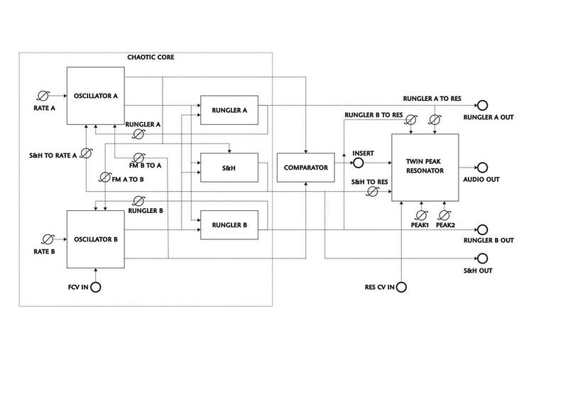
Below is the signal flowchart of Blippoo box, by Rob Hodjik. Here is a video of it : https://vimeo.com/35652683
Rungler is a 3 bit shift register with one oscillator as clock and the other as the sampling source.
I have written a bit of code, but it doesn't work. Please check it below. Thanks.
#include <MozziGuts.h>#include <tables/square_no_alias512_int8.h>#include <Oscil.h>#define CONTROL_RATE 64
Oscil <SQUARE_NO_ALIAS512_NUM_CELLS, AUDIO_RATE> osc0(SQUARE_NO_ALIAS512_DATA);Oscil <SQUARE_NO_ALIAS512_NUM_CELLS, AUDIO_RATE> osc1(SQUARE_NO_ALIAS512_DATA);
byte currentByte[2];boolean oscState[2];Q8n0 rungler[2];Q16n16 runglerDepth[2], FMDepth[2];
void setup() {  startMozzi(CONTROL_RATE);  for (int i = 0; i < 2; i++) {    rungler[i] = 0;    runglerDepth[i] = 50000;  }  osc0.setFreq(255);  osc1.setFreq(522);}
void updateControl() {}
int updateAudio() {  int sig[2];  sig[0] = osc0.phMod(rungler[1] * runglerDepth[1] + sig[1] * FMDepth[1]);  sig[1] = osc1.phMod(rungler[0] * runglerDepth[0] + sig[0] * FMDepth[0]);
  for (int i = 0; i < 2; i++) {    if (sig[i] > 0 && !oscState[i]) {      oscState[i] = 1;      if (currentByte[i] < 2) currentByte[i] += 1;      else currentByte[i] = 0;      if (sig[1 - i]) rungler[i] = rungler[i] | (B00000001 << currentByte[i]);      else rungler[i] = rungler[i] & (B11111110 << currentByte[i]);    }    if (sig[i] < 0) oscState[i] = 0;  }
  long audio = sig[0] + sig[1];
  return audio << 2;}
void loop() {  audioHook();}
Tim Harrington
Sep 25, 2015, 4:14:55 PM9/25/15
to Mozzi-users
Hey there, weirdly, this is my first post here after lurking for a month or so while using the library for a project and am getting comfortable/into it enough to join the crowd.
I'm not totally following your code but right off the bat I can see that you're doing a lot of computation in update audio. Without combing through it I sense that there must be some parts that can get pulled into update control. I had some imbalances there m'self pull everything you can out of updateAudio so it can run fast.
I'd recommend adding a lot of commenting to that code explaining what you think each part should be doing functionally and maybe a serif bit on how the code is working on it.
I know the Blippo Box. It is confusing to breakdown into parts even hearing it or seeing the block diagram. I think writing out the steps and functions in human words first then translating to Mozzi would make it easier for someone to offer coding help.
like:
there are two oscillators(A and B) fm each other
there are 2 shift registers(binary arrays): 1 shift register collects the value of A at the frequency/rate of B the other collects B at freq/rate of A
the shift registers values are converted from a binary value into an int - that int value FMs(or modifies somehow) one of the two oscillators respectively.
and on and on...
Not much help really but maybe helping to get help....

Tim Barrass
Sep 26, 2015, 2:19:16 AM9/26/15
to mozzi...@googlegroups.com
Hey Tim,
that is excellent advice!
I'm no expert programmer, and would not normally offer advice about how to code, but as the author of this library I feel I can chime in here and strongly recommend the approach explained by Tim Harrington above.
Thanks Tim! Take heed all Mozzi programmers!
Cheers,
Tim B.
To view this discussion on the web, visit https://groups.google.com/d/msgid/mozzi-users/f1765a4c-8aa0-441b-afe8-cb17729442f9%40googlegroups.com.--
You received this message because you are subscribed to the Google Groups "Mozzi-users" group.
To unsubscribe from this group and stop receiving emails from it, send an email to mozzi-users...@googlegroups.com.
To post to this group, send email to mozzi...@googlegroups.com.

Dan Bosnyak
Mar 9, 2016, 12:35:39 PM3/9/16
to Mozzi-users
Meng,
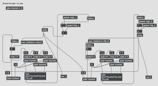 This is a very interesting project, I am working on the same thing. I can see some immediate issues with your code. I advise you to take out the rungler and get it working with just the two VCOs cross modulating each other first. You have one square wave phase modulating another. Imagine OSC1 is going quickly and OSC2 is slow. When OSC2 is zero, OSC1 runs as normal. When OSC2 switches to 1 output, OSC1 immediately jumps in phase by FMDepth units (which you have left uninitialized). THis would not work as an instantaneous jump in phase will just sound like a click. You need to use frequency modulation instead, that is set the frequency of OSC1 based on the voltage of OSC2. You will have to choose some appropriate scale for this. I am attaching a block diagram of a rungler in Max which might be of use to you.
 This is a very interesting project, I am working on the same thing. I can see some immediate issues with your code. I advise you to take out the rungler and get it working with just the two VCOs cross modulating each other first. You have one square wave phase modulating another. Imagine OSC1 is going quickly and OSC2 is slow. When OSC2 is zero, OSC1 runs as normal. When OSC2 switches to 1 output, OSC1 immediately jumps in phase by FMDepth units (which you have left uninitialized). THis would not work as an instantaneous jump in phase will just sound like a click. You need to use frequency modulation instead, that is set the frequency of OSC1 based on the voltage of OSC2. You will have to choose some appropriate scale for this. I am attaching a block diagram of a rungler in Max which might be of use to you.
On Wednesday, 23 September 2015 01:27:11 UTC-4, Meng Qi wrote:
Below is the signal flowchart of Blippoo box, by Rob Hodjik. Here is a video of it : https://vimeo.com/35652683
Rungler is a 3 bit shift register with one oscillator as clock and the other as the sampling source.
I have written a bit of code, but it doesn't work. Please check it below. Thanks.
Reply all
Reply to author
Forward
0 new messages