Cheap active commutator + basic miniscope software in Labview
696 views
Skip to first unread message

Roman Doronin
Aug 4, 2021, 12:41:14 PM8/4/21
to Miniscope
Hello everyone!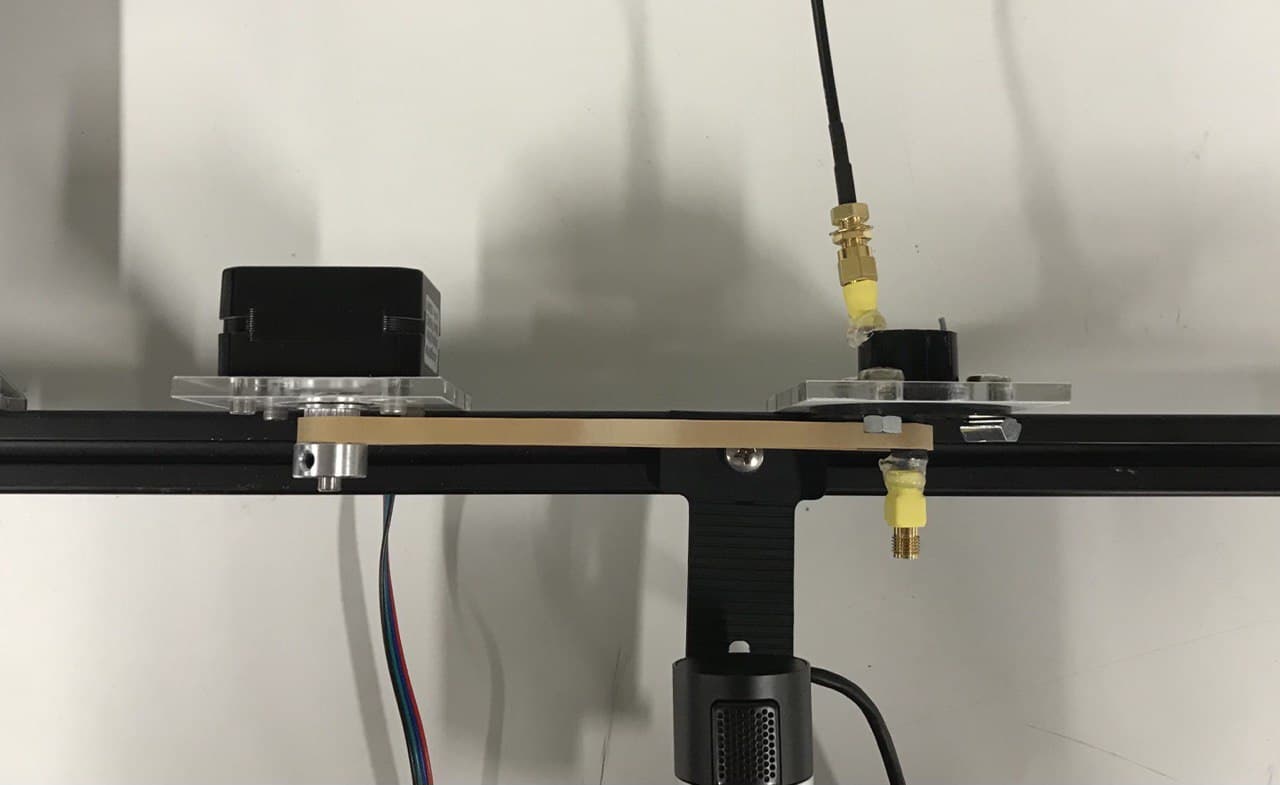
As Miniscope V4 outputs head orientation signal, it is possible to use it to make a cheap active commutator that does its job reasonably well. Here is how I made it:
The basic construction is very simple: passive slip-ring commutator (smth like this) + stepper motor connected with a rubber band, everything is attached to the metal bar.
To control the stepper I used EZHR17EN driver (and Labview software is written for this driver). USB commands are first converted to UART commands via USB-UART converter before reaching the driver.
The idea of the code is that stepper turns with the fixed speed (that can be changed on the panel) to the angle equal to the difference between two consecutive sampled yaw angles.
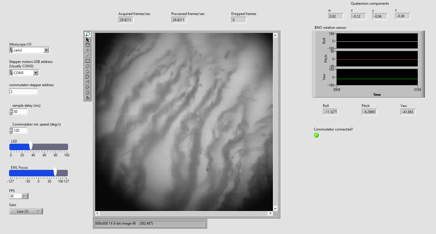
Besides extracting just head orientation signal, I implemented the very basic image capture of the miniscope image and the control of its parameters (LED, gain, etc.). This can be used as the base platform for creating setups with more or less complex control loops, e.g. using head orientation signal to control something else besides commutator.
The interface looks like this:
Code is located here:
https://sourceforge.net/p/iris-scanning/aux-code/HEAD/tree/Behavior/Arena/
Main vi is MiniscopeCommutatorController.vi. It needs the following subvis:
QuaternionsToEuler.vi
InitializeStepperUSBDevice.vi
CommutatorStepperSendCommand.vi
Hope someone finds it helpful.
Roman

Daniel Aharoni
Aug 4, 2021, 4:10:33 PM8/4/21
to Miniscope
Wow! Thanks for posting this Roman. Looks great!

qingchun guo
Aug 19, 2021, 4:52:28 AM8/19/21
to Miniscope
Hi, Roman. Amazing work! I think it's quite useful to acquire the images of miniscope using Labview. It's a little hard to read the program you attached here. Can you share with me a pure program that only contains the functions of controlling and acquiring for miniscope? I also want to know if it is possible to control the miniscope V3 or Ninscope using Labview? And where should I modify based on your code? Thanks for your help!
Best regards!
Qingchun Guo
Roman Doronin
Aug 19, 2021, 6:12:37 AM8/19/21
to Miniscope
Yes, in MiniscopeCommutatorController.vi it should be enough to delete the very bottom while loop that controls the commutator. The remaining loops will be the ones that acquire image, BNO sensor data and control the miniscope parameters. It should be possible to control V3 and Ninscope too, but I suspect that as the PCBs on V3 and Ninscope are different, the exact control commands that should be sent will be different from the ones that are written in Labview. To understand which commands should be sent for V3 you might need to use USB sniffer (I used Wireshark) to look which commands are sent by the native miniscope software. This thread might help: https://groups.google.com/g/miniscope/c/iHKt1xRRg_M/m/QRaneUXvFQAJ
Best,
Roman
qingchun guo
Aug 19, 2021, 8:55:21 PM8/19/21
to Miniscope
OK, I will try. Now the program of V4 is normally run, looks great! Thanks for your help, Roman!
Best regards!
Qingchun Guo

earthw...@gmail.com
Jan 2, 2022, 11:32:32 PM1/2/22
to Miniscope
Dear
Roman
Hi. Roman. As my commutator is quite troublesome while doing the behavior test with miniscope recording, I am planning to use your nicely made commutator and related NI codes. I do have some questions though, does this commutator program also support TTL input function, just like the classic Miniscope DAQ software? In addition, can I also know what stepper motor that you are using? Thanks a lot for your help :D
Sincerely,
Gaeun Park
2021년 8월 20일 금요일 오전 9시 55분 21초 UTC+9에 bmp.g...@gmail.com님이 작성:
Roman Doronin
Jan 3, 2022, 5:25:42 AM1/3/22
to Miniscope
At the moment it doesn't support external triggering via TTL input. What MiniscopeRecorder.vi does is upon the pressing Record button, it changes the state of the Shutter functional global variable and writes 5V to the output TTL signal (so it can be used somewhere else). So to make the code externally triggerable, you should copy the external TTL input and feed the copy to the NI DAQ device and change the code by reading this input channel from NI DAQ and change the state of Shutter functional global upon the edge detection in this input signal. If you don't have NI DAQ, then so far I don't know how to make it work: software should know somehow about the state of the external TTL signal and I don't know how to extract this information purely from the USB signal coming from miniscope DAQ. Hope it was clear.
Stepper was the flat nema 17 motor, smth like this https://www.aliexpress.com/item/1005003118540606.html , torque doesn't matter that much I guess.
Stepper was the flat nema 17 motor, smth like this https://www.aliexpress.com/item/1005003118540606.html , torque doesn't matter that much I guess.
earthw...@gmail.com
Jan 11, 2022, 3:37:27 AM1/11/22
to Miniscope
Dear Roman
Thanks for your kind reply. I do have one question though regards this Labview program. I am about to create a new Labview, but while testing the original code that you have been shared, this Labview code (with NI Labview 2021) shows miniscope imaging, but cannot manipulate EWL, gain, and light intensity. As Qingchun Guo from upper section mentioned that this program works fine, so I wonder whether I am using any different software or miniscope hardware. I just upgrade the miniscope DAQ firmware, and I am currently using miniscope V4.4. Would this make any problem on using your labview code?
Gaeun
2022년 1월 3일 월요일 오후 7시 25분 42초 UTC+9에 bast...@gmail.com님이 작성:
Roman Doronin
Jan 11, 2022, 4:01:37 AM1/11/22
to Miniscope
Oh, I forgot to mention one thing that could be the reason why it's not working: so far I haven't implemented the miniscope initialization procedure via my Labview code, so it needs to be done via the original miniscope software. Try to open original miniscope software, then close it and open the Labview one. Also, some parts of the code are needed only for my particular setup (e.g. perturbations) so feel free to throw away these parts if you don't need them.
earthw...@gmail.com
Jan 12, 2022, 4:22:18 AM1/12/22
to Miniscope
Dear Roman
Aha, that was the one point that I need. Now I confirmed that the code successfully work when I operate it as you suggested. It can be used in such way, but do you have a plan to modify the software in an upcoming future?
Sincerely,
Gaeun Park
2022년 1월 11일 화요일 오후 6시 1분 37초 UTC+9에 bast...@gmail.com님이 작성:
Roman Doronin
Jan 19, 2022, 11:32:33 AM1/19/22
to Miniscope
Yes, I am planning at some point to add the initialization procedure and improve the code overall. If you have specific ideas of what can be improved - let me know!
earthw...@gmail.com
Feb 5, 2022, 1:48:17 AM2/5/22
to Miniscope
Dear Roman
Hi. As I am not quite sure how to code the labview for the initialization procedure, I just edited your code a little, so that I can initiate miniscope and other external camera. During modification, several questions got me:
1) Very intriguingly, your commutator code works perfectly (except the initiation) for the miniscope handling in one PC, but not others. I used same DAQ and same miniscope, but in other PCs (that your code seems to not work oddly), the LED and EWL control seems to be a bit slow or delayed, which eventually leading to blinking LED. However, the image acquisition and head orientation information acquisition seems to be fine. I wonder whether you have any idea or any moment facing such issue. All PCs are installed with Labview 2021, but little variations on the extentions (?) that were installed along with Labview 2021 by VI package manager.
Other than the code, there is also an issue in the physical condition:
2) I did the soldering procedure correctly, double check for the current and resistance with the multimeter, but when I connect my miniscope+commutator+coaxial cable to the DAQ, it shows the common image acquisition error message. I used a common slipring(Cat# SVTS A 03, https://www.servotecnica.com/en/products-p/rotary-joints/electric-rotary-joints-slip-rings/svtsa-capsule-slip-rings/) with two wires connected to the axial cable (one to inner conductor and the other to the coax shield (GND)). I wonder whether I have to connect more than just two wires (maybe use all 6 wires?) to prevent such error.
Sorry to bother you with those questions, but it would be a great help if you can answer those questions :D
Gaeun
2022년 1월 20일 목요일 오전 1시 32분 33초 UTC+9에 bast...@gmail.com님이 작성:
earthw...@gmail.com
Feb 10, 2022, 2:22:57 AM2/10/22
to Miniscope
If there is anyone interested in this discussion:
1) I realized that this particular labview software works well in the Intel but not AMD by some unknown reasons (test in 3 Intel PCs and 3 AMD PCs all have Labview2021 with all add-on installed)
2) Commutator works well if you solder the parts with more cables of slip ring
One question that is not solved yet:
When I manipulate the LED intensity, it is being modulated well except brightness 0. I cannot completely turn off the LED but showing a dim blue light. To avoid any moment of unintended photobleaching, I'd like to turn off the miniscope LED on the moment that I am not recording the calcium signal. I am afraid whether this setting of dim light as 0 is actually intended by some reason or only happen in my PCs.
Is there anyone who experienced such issue?
Gaeun
2022년 2월 5일 토요일 오후 3시 48분 17초 UTC+9에 earthw...@gmail.com님이 작성:
Roman Doronin
Feb 14, 2022, 7:12:55 AM2/14/22
to Miniscope
1) About this I unfortunately have no clue:(
2) Great that it worked! Although for my slip ring only two wires was enough.
3) About the LED not shutting down: it was the bug in my code. I corrected it now and pushed to Sourceforge, but if you want to modify it yourself, you only need to add 0.001 to the value written to Gamma in the first LED command: for some reason for some values Labview floor the values but it is present only for some particular values, and only for Gamma attribute. In particular, instead of FF01 command it was sending FF00.
Before: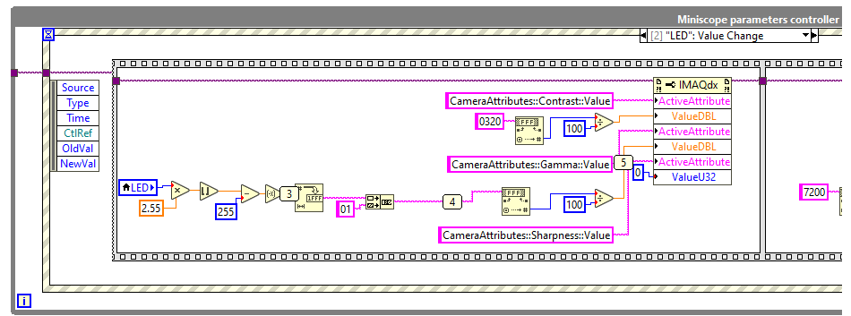
After: 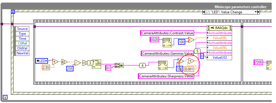
earthw...@gmail.com
Feb 18, 2022, 9:20:58 PM2/18/22
to Miniscope
Dear Roman
Thanks for such kind reply! I now can turn off the LED completely. Thanks again for your gorgeous Labview code!
Gaeun
2022년 2월 14일 월요일 오후 9시 12분 55초 UTC+9에 bast...@gmail.com님이 작성:
Reply all
Reply to author
Forward
0 new messages