Scanning horizontal lines with pcb v4.40
584 views
Skip to first unread message

Ariel Burman
Jul 1, 2021, 4:17:17 PM7/1/21
to Miniscope
Hello Everyone,
I'm testing two miniscopes that I've recently build with the flex PCB v4.40.
When I set the LED intensity above 80 I start seeing some horizontal scanning lines. When I reach to 100 there are some thick black lines also in a horizontal scanning style.
I had the idea that the v4.40 PCB was absent of this problem.
I have also 2 miniscopes with version PCB v4.2 that also show these behavior although I understand that was expected and we are going to try to fix with the "hot fix PCB".
I attach 4 videos, one with each miniscope. 1 & 2 are the v4.2 miniscopes. 3 & 4 are the v4.40 miniscopes.
I'm using the software v1.10 and DAQ 3.3. A usb cable around 1 meter long and each miniscope has the 3 meter coax cable
From the videos I can see that with v4.40 I get more clear image (using same gain x1 in all videos) for the same set of LED. And there is no scanning lines below LED intensity 75.
So at the end, the PCB v4.40 does works better. My question is, is it normal to still have that problem when I set a high intensity? Or I should expect to not have it and I'm having another problem that I'm not aware of?
Thank you

Daniel Aharoni
Jul 1, 2021, 7:08:28 PM7/1/21
to Miniscope
Hi,
So the issue you are seeing is something different than what was previously fixed by the "hot fix PCB" and in all V4 Miniscope with version v4.4 or higher.
What you are seeing is one of two things (and potentially the combination for both). When the LED intensity is turned up very high, usually above 70 ort 75, the amount of electrical current it draws can cause:
- A larger voltage drop across the coax cable, especially with thinner and/or longer cables, which results in too low of voltage reaching the Miniscope. When powered off USB, the output voltage of the DAQ is 5V. The Miniscope needs above ~3.5V to run properly but when a large amount of current flows across the coax cable, this 5V supply can drop below 3.5V.
- The voltage regulator on the Miniscope that supplies voltage to the LED and other electronics maxes out at 200mA. When the LED intensity goes very high, usually above 80 or 90, this can cause the voltage regulator to max out its current output and become unstable.
So in both of these cases, the voltage, and potentially the current, supply on the Miniscope itself can become unstable. This then causes the image sensor to also become unstable and produce the lines you are seeing. A potential solution that can sometime solve this issue is to decrease the length of the coax cable or to power the DAQ using a 6V DC jack.
In the end though, going over 70 in LED intensity should generally not be done as this ends up being a ton of light going into the brain. Generally speaking, for good GCaMP6f or better expression you might not need to go over 20 or 30. For dimmer fluorophores or non-optimal expression, 50 is a good place to aim and I would suggest trying to stay well under 70.
Finally, you can try changing the FPS and Gain of the Miniscope instead of maxing out the LED. Decreasing FPS or increasing the Gain will result in a brighter image without the need to increase the LED.

Alessandro Di Filippo
Jul 2, 2021, 5:09:42 AM7/2/21
to Miniscope
If I may add something, I had the exact same problem with one mouse, where I had to keep a high LED value.
The Miniscope worked pretty well when connected to the DAQ, even in absence of an external power supply, but did not when connected to the commutator, even with a power supply with 6V, probably because of the added cable length.
In my case, after getting a bit of advice here, I was able to solve the issue by simply cutting the cable and making it shorter (the original cable length was already a bit too much). You can easily order some SMA connectors to do it, you will just need a magnifying lens and a scalpel blade for getting out the signal wire.
Ariel Burman
Jul 2, 2021, 9:36:29 AM7/2/21
to Miniscope
Great
Thank you for the explanation.

Eric Melonakos
Jul 23, 2021, 2:53:57 PM7/23/21
to Miniscope
Hi Daniel,
Should the DC jack be 6V or 9V? The DAQ schematic says 9V, but the Power Jumper section on the same page says between 5 and 12V is acceptable, so maybe it doesn't matter...
Thanks,
Eric
Daniel Aharoni
Jul 23, 2021, 3:23:48 PM7/23/21
to Miniscope
Hi, you should go with as low of a voltage as needed to get stable functionality. In almost all cases, 6V is enough and will result in less heating of the PCBs.
Eric Melonakos
Jul 23, 2021, 10:35:11 PM7/23/21
to Miniscope
OK, thank you.

Fa Peng
Jul 24, 2021, 10:30:58 PM7/24/21
to Miniscope
Hi Daniel,
Can we use a higher voltage for the V4 Miniscope through the DC jack? In my opinion, the v4.4 version of the V4 Miniscope can withstand 6V. Higher voltage (9V) may damage some chips, such as NCP163AMX330TBG (maximum input voltage 6V).
Is my understanding correct?
Daniel Aharoni
Jul 25, 2021, 5:38:59 PM7/25/21
to Miniscope
Great points! When switching over to using the DC jack on the DAQ and sending a voltage higher than 5V to the Miniscope we still want the voltage that reaches the Miniscope not to exceed 5V by too much (and ideally this should be closer to 4V). When supplying over 5V from the DAQ you are looking to mainly account for the voltage drop that occurs across the coax cable so that the voltage the Miniscope sees isn't too low (which is usually around 3.5V).
As you mentioned, care should be taken so that the voltage at the Miniscope isn't much above 5V or 6V.

ph prouvot
Jul 29, 2021, 8:59:35 AM7/29/21
to Miniscope
Hello,
If I may add my question to this subject because I experience a similar issue. I also get horizontal lines during recording as well as black dots appearing on and off.
The LED doesn't seem to flicker and I replaced the coaxial cable because it wasn't connecting properly. Before the change of cable during the few times when the connection was working properly the exact same artifacts appeared. The cable we have is 2m long.
I hope we didn't fry everything by shortly (a few seconds) connecting it to 12V Jack before we realized we took the wrong adaptor. It was also heating seemingly a bit too much and already presented these imaging artifacts before that mistake.
It's a miniscope v4.4 that we tried to use with the miniscope software as well as pomidaq.
Do you have any idea what the problem could be?
I can create a new subject of course if that's more convenient.
Thank you
Daniel Aharoni
Jul 29, 2021, 3:47:16 PM7/29/21
to Miniscope
Hi,
What value do you have the LED set to and which type of coaxial cable are you using (where is it from or what is the diameter of it)? It could be very likely that applying 12V, even for a short period of time, could have damaged critical components on the DAQ and/or on the Miniscope. We have never applied 12V ourselves so I am not sure exactly what would fail first and what the resulting connection would look like.
If I understand correctly, these image artifacts showed up before you applied 12V. The closest thing I have seen to this is when the LED is drawing a ton of current which makes some of the voltage regulators a bit unstable. That being said, I haven't ever seen this exact set of artifacts and don't think I have ever seen where you get a salt and pepper scattering of black pixels.
ph prouvot
Jul 30, 2021, 12:45:39 PM7/30/21
to Miniscope
Hi,
We are using the 1mm diameter 2m long coaxial cable from open ephys, the first we received had issues connecting to the DAQ (data link LED flickering or not turning on) and these lines were showing up the few times it did work, the second one connects fine. I checked the first recording I did though and the dead pixels weren't there.
We might try to save the components and change the PCB if we fried it.
Daniel Aharoni
Jul 30, 2021, 4:07:36 PM7/30/21
to Miniscope
Hi, 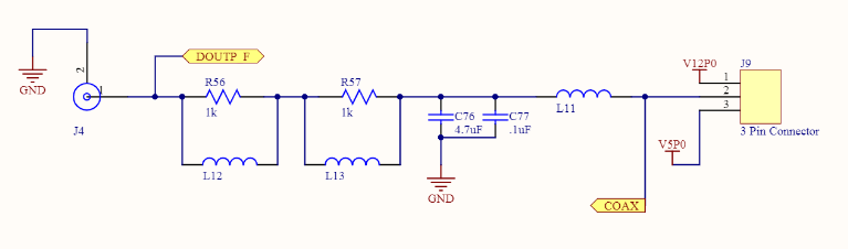
Ok most likely it sounds like components relating to the image sensor on the V4 PCB are damaged now. You can likely request a quote for only the PCB from OEPS and swap it out yourselves. There is a small chance that a few components on the DAQ are damaged as well due to the higher voltage but I think this is unlikely. If anything was damaged on the DAQ it would be just some of these cheap capacitors and/or inductors shown below which are very easy to replace by hand.
ph prouvot
Aug 2, 2021, 5:24:25 AM8/2/21
to Miniscope
Hi,
We will order a new PCB and ask someone better than me at soldering to swap it. We'll then see if there is issues with the DAQ.
Thank you very much for the help have a nice day.

Hannah Wirtshafter
Aug 3, 2022, 5:02:05 PM8/3/22
to Miniscope
How short did you trim your cable to? Thanks!
Hannah
Reply all
Reply to author
Forward
0 new messages