Head Orientation
493 views
Skip to first unread message

Miguel Carvalho
Jan 22, 2021, 4:18:40 PM1/22/21
to Miniscope
Hi,
I have been looking into using the head orientation information provided by the V4 miniscopes to assess animal movement direction. A couple of questions have come up.
The .csv file shows values for qx, qy and qz, which I assume are the values for the orientation of the head in the X, y and Z plane. However, it is unclear to me what qw represents.
Secondly, the values seem to vary between -1 and 1, especially in the Z plane. I would expect the X and Y planes to show a similar range but they appear to have a somewhat shorter range. Is this expected? I could imagine the animal tilting the head in either the X or Y plane and reach max/min positions, similar to the Z plane. Is it related with the internal frame of reference of the miniscope, and if so how is that reference set up to begin with?
Thanks in advance!
Miguel

Daniel Aharoni
Jan 22, 2021, 5:51:46 PM1/22/21
to Miguel Carvalho, Miniscope
Hi Miguel,
Thanks for the question.
The head orientation data is actually stored in a quaternion (https://en.wikipedia.org/wiki/Quaternion#:~:text=Quaternions%20were%20first%20described%20by,the%20quotient%20of%20two%20vectors.). It is a vector of length 4 which holds angular position. Generally people will want to convert this to Euler Angles as this will give more meaningful measure for each term. That being said, quaternions have a few important advantages over Euler Angles and is why we save our head orientation data in that form.
To help you with the conversion, MATLAB has a built in function to go from quaternion to euler angle but I am also putting code below to do this conversion:
double m00 = 1.0 - 2.0*qy*qy - 2.0*qz*qz;
double m01 = 2.0*qx*qy + 2.0*qz*qw;
double m02 = 2.0*qx*qz - 2.0*qy*qw;
double m10 = 2.0*qx*qy - 2.0*qz*qw;
double m11 = 1 - 2.0*qx*qx - 2.0*qz*qz;
double m12 = 2.0*qy*qz + 2.0*qx*qw;
double m20 = 2.0*qx*qz + 2.0*qy*qw;
double m21 = 2.0*qy*qz - 2.0*qx*qw;
double m22 = 1.0 - 2.0*qx*qx - 2.0*qy*qy;
double R = atan2(m12, m22);
double c2 = sqrt(m00*m00 + m01*m01);
double P = atan2(-m02, c2);
double s1 = sin(R);
double c1 = cos(R);
double Y = atan2(s1*m20 - c1*m10, c1*m11-s1*m21);
qw, qx, qy, and qz are the 4 values of a quaternion. The 'm' variables are actually entries in a 4x4 transformation matrix but we aren't using the whole matrix so I only calculate some of them to then be used to generate R, P, and Y which are Roll, Pitch, and Yaw respectively.
--
You received this message because you are subscribed to the Google Groups "Miniscope" group.
To unsubscribe from this group and stop receiving emails from it, send an email to miniscope+...@googlegroups.com.
To view this discussion on the web visit https://groups.google.com/d/msgid/miniscope/eceaae01-24e1-42ca-a76f-ce49c6b2852cn%40googlegroups.com.
Daniel B. Aharoni, PhD
Assistant Professor
Dept. of Neurology, UCLA
Dept. of Neurology, UCLA
miguelmv...@gmail.com
Jan 23, 2021, 7:56:54 AM1/23/21
to Daniel Aharoni, Miniscope
Hi Daniel,
Thanks for the clarification. So in essence, if one disregards head tilts, head direction will be directly given by the yaw angle expressed in radians, correct?
Best,
Miguel
On 22 Jan 2021, at 23:51, Daniel Aharoni <dbah...@gmail.com> wrote:

Ana Gonçalves
Feb 11, 2021, 12:15:28 PM2/11/21
to Miniscope
Hi Daniel,
Thanks a lot for this clarification. I have a few questions about the head orientation sensor:
1. what type of inertial sensor device is embedded in the Miniscope? I've used a device in the past that had an accelerometer, gyroscope and magnetometer all combined
2. Could you give an intuition of what an "absolute head orientation sensor" means? As far as I'm concerned, the calibration of these devices is very tricky
3. I've started plotting the roll, pitch and yaw angles of the sensor and comparing it with the tracking of the mouse's nose. Do you have any tips (besides looking at the logo rotation during the behavior) for getting a sense of what X, Y and Z are in relation to the behavior I'm measuring (linear treadmill)?
Thanks a lot!!
Ana
Daniel Aharoni
Feb 11, 2021, 12:28:12 PM2/11/21
to Miniscope
Hi Ana,
1. The V4 Miniscope has a Bosch Bno055 sensor on it. This sensor has a 3 axis accelerometer, magnetometer, and gyroscope and is able to fuse the data from these individual sensors into euler angles or quanternion.
2. The Bno055 handles the calibration and fusion of the acc, mag, and gyro internally. It is possible to get the raw data from any of these sensors but currently the Miniscope DAQ platform only requests the resulting quanternion.
3. I will try to remember to look this up and get back to you as I am not on my computer right now. I am pretty sure I have set it up such that the z axis of the euler angle is pointing up from the mouse's skull. The X axis should be facing from the center of the Miniscope towards the part of the scope that has the coax cable connector on it.
Ana Gonçalves
Feb 11, 2021, 12:32:19 PM2/11/21
to Daniel Aharoni, Miniscope
Cool, thanks a lot!
This is a really cool feature and the format it outputs its much easier to handle.
I’m really looking forward to use this in my data!!
To view this discussion on the web visit https://groups.google.com/d/msgid/miniscope/01285c43-898e-4fe3-b92e-13967d40d819n%40googlegroups.com.
Ana Gonçalves
PhD Student at the Neural Circuits and Behavior Lab
Champalimaud Foundation
Av. de Brasília, Doca de Pedrouços
1400-038 Lisboa, Portugal
Champalimaud Foundation
Av. de Brasília, Doca de Pedrouços
1400-038 Lisboa, Portugal
Ana Gonçalves
Mar 23, 2021, 11:41:57 AM3/23/21
to Daniel Aharoni, Miniscope
Hi Daniel,
Did you have the chance to check the external world axis of the BNO in relation to the Miniscope?
Thanks a lot!
To view this discussion on the web visit https://groups.google.com/d/msgid/miniscope/01285c43-898e-4fe3-b92e-13967d40d819n%40googlegroups.com.
Daniel Aharoni
Mar 23, 2021, 5:38:34 PM3/23/21
to Miniscope
Hi Ana,
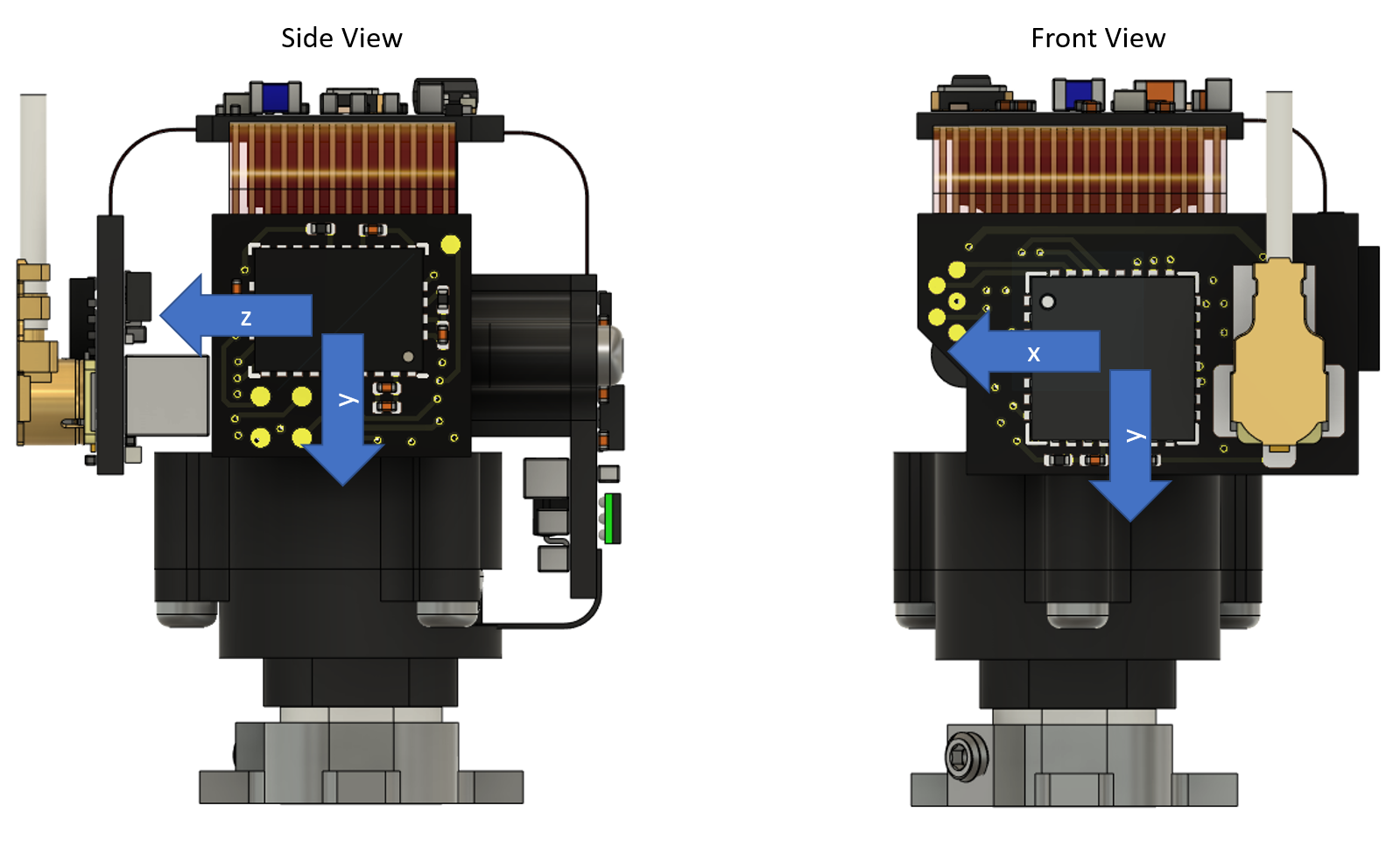
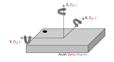
I think the rendering below should be correct. The z-axis faces out from the PCB that has the coax cable connection on it. The y-axis faces down to the mouse. The x-axis faces out from the side of the V4 Miniscope that doesn't have any PCBs on it.
The saved quaternion data is based off this axes configuration.

Fa Peng
Mar 24, 2021, 9:38:36 PM3/24/21
to Miniscope
Hi Daniel,
I think your marking 'z-axis ' should be -z, according to my understanding of BNO055's datasheet and your code.
The picture is my understanding of the coordinate system (please ignore the Chinese, I don't think it will affect the relevant understanding). I will check the data sheet and your code again to see if it is correct.
Daniel Aharoni
Mar 25, 2021, 2:49:03 PM3/25/21
to Miniscope
Hi,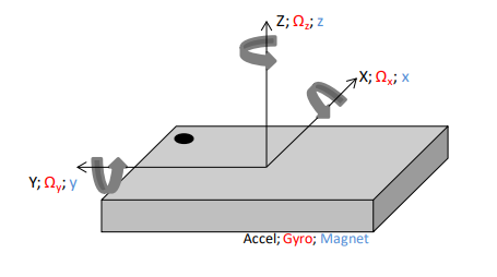
I definitely could have calculated things incorrectly. This is what I did:
- The BNO055 axes get remapped and flipped by the AXIS_REMAP_CONFIG and AXIS_REMAP_SIGN registers in the BNO. The Miniscope system updates these 2 registers when the system connects to a Miniscope and those values can be found in the initialization section of the Miniscope_V4_BNO videoDevices.json value.
- The AXIS_REMAP_CONFIG should get set to 0b0001001
- x -> y
- y -> z
- z -> x
- The AXIS_REMAP_SIGN should get set to 0b00000101
- The sign of the remapped x flips
- The sign of the remapped z flips
- This should result in:
- x -> y
- y -> -z
- z -> -x
Fa Peng
Mar 29, 2021, 3:29:18 AM3/29/21
to Miniscope
Hi Daniel,
I think your opinion is correct. I made a mistake with the default coordinate system and coordinate origin.
Thanks a lot.
Daniel Aharoni
Jun 29, 2021, 4:01:58 PM6/29/21
to Miniscope
So it turns out that my previous post about the final axis orientation of the BNO, head orientation, sensor on the V4 Miniscope was incorrect. Below should be the correct orientation of the save quaternion data.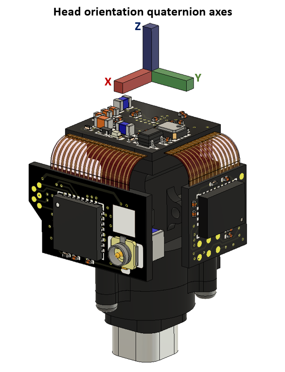
Fa Peng
Jul 6, 2021, 2:00:07 AM7/6/21
to Miniscope
Hi Daniel,
If the current head orientation(the final axis orientation) is correct, the default coordinate system in the BNO055 datasheet is wrong, which possibility is very small; I can't find more information to confirm the default coordinate system of the BNO055 datasheet at present. Whether the change of qx(saved in the file of 'headOrientation.csv') represents the corresponding X axis, this is a question that should be studied, but I don't quite understand quaternions.
Can you give a detailed description on how to get the current coordinate system?
Thanks a lot.
Daniel Aharoni
Jul 6, 2021, 4:20:37 PM7/6/21
to Miniscope
Hi,
Sure thing and seeing as I made a mistake previously on this thread it would be great to have another pair of eyes looking at it. That being said I am 99.5% sure I have it correct now.
So the default coordinates of the BNO are show below:
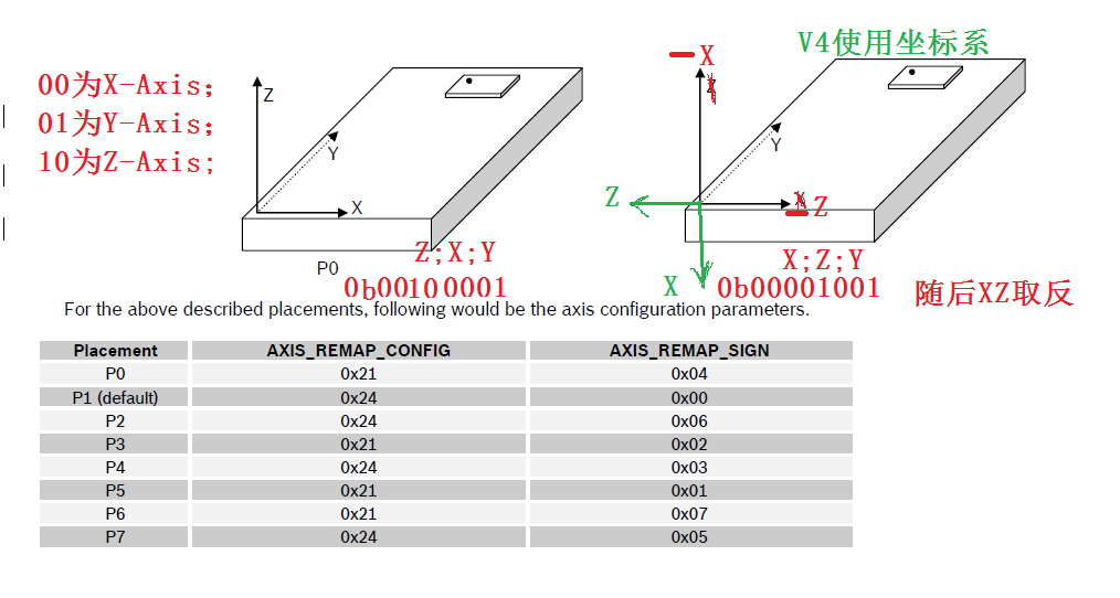
Now when the V4 Miniscope powers up the DAQ software sends a set of commands to the BNO to remap these axes (you can take a look at it in the initialization section of the videoDevice.json if interested). These commands are the following:
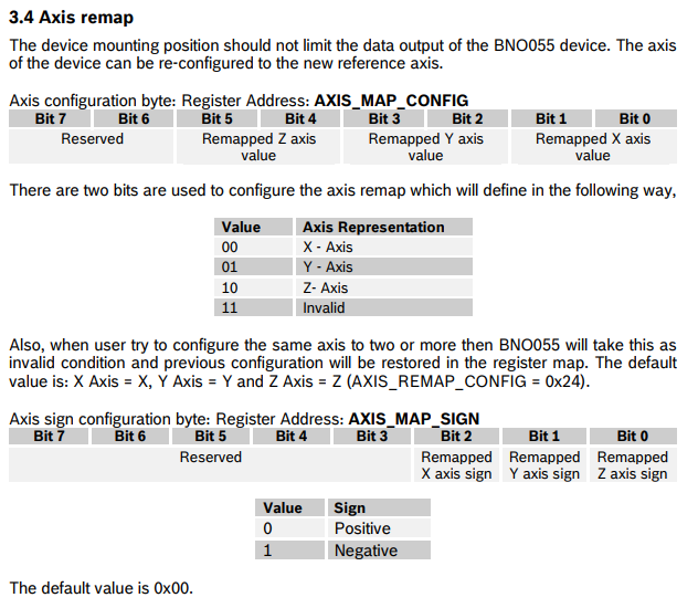
- register 0x41 (AXIS_MAP_CONFIG) gets set to 0b00001001
- register 0x42 (AXIS_MAP_SIGN) gets set to 0b00000101
The description of register 0x41 is slightly confusing in the BNO datasheet as it can be potentially read in 2 ways (which is the reason the orientation I initially posted was wrong) but I am posting the relevant part below:
The changes we make to these registers should place:
- x in the default y position
- y in the default z position
- z in the default x position
- Finally it flips the sign of x and z.
With this all combined I think you end up with the head orientation I posted last week.
Fa Peng
Jul 6, 2021, 10:12:16 PM7/6/21
to Miniscope
Hi Daniel,
in my opinion,the default coordinates of the BNO are corresponding to P1 placement(0x24 in register 0x41).0b00100100(0x24) represents ZYX axes of the default coordinates.When the register 0x41 was set to 0b00001001,
z(default value 10) -> x(value 00)
y(default value 01) -> z(value 10)
x(default value 00) -> y(value 01)
0b00100100(0x24) is changed to 0b00001001.
Where is the problem? Did I miss something?It seems that I made the same mistake, but I don't understand the wrong place so far.
Daniel Aharoni
Jul 7, 2021, 4:48:53 PM7/7/21
to Miniscope
Hi,
So I think the issue here is interpreting "Remapped X/Y/Z axis value". The axis value that goes in these bits defines which default axis the remapped axis gets mapped to. This effectively flips the mapping you previously wrote out. For instance, instead of z -> x it actually is x -> z.
Fa Peng
Jul 8, 2021, 1:45:58 AM7/8/21
to Miniscope
Thanks a lot.

Peter Wang
Feb 23, 2023, 2:26:39 AM2/23/23
to Miniscope
Hi all,
I'm 2 years too late but hopefully this will be help to anyone in the future. In response to Miguel's question, yes exactly. You take the yaw angle from the Euler angles and that would be your yaw /azimuthal angle.
To get the phase offset between the sensor reference frame and the experimental reference frame, I did the following:
- take rough estimates of head direction in the camera-centric reference frame by looking at mouse heading for a few frames (I've found that good estimates can be derived using frames in which the mouse's head is flat / while it's running)
- compare this to the sensor's yaw values. The phase offset should be consistent across all frames (i.e. high R^2).
Best,
Peter
Reply all
Reply to author
Forward
0 new messages