MFM Reader (dumper) on Raspbery pico?
356 views
Skip to first unread message

tronix286
Nov 15, 2022, 8:56:52 AM11/15/22
to MFM Discuss
Hello,
I recently bought some MFM hard drives from a flea market and would like to see what they contain. Unfortunately, I don't have a beaglebone board, but I do have a raspbery pi pico.
Rpi Pico have hardware PIO (programmable IO) block probably a bit like a PRU block at beaglebone, if i understand correctly. Rpi pico can operate PIO GPIO at full core speed set by default to 125MHz, but it possible to slightly overclock to 200MHz. Also Rpi Pico has DMA and possible to transfer 32 bit data between PIO and DMA at one core cycle.
I'm new to programming and haven't fully read the documentation yet, but at first glance this should read an entire track into the controller's memory .I want to try if you don't dissuade me.
My rough plan is:
- raspberry pico will be a simple performer. Basically, these are all the functions that are in the prucode0.p and drive_operations.p files;
- Raspberry must be able to read an entire track into its memory and then slowly forward it to the main host computer (with help UART or USB Virtual COM port);
On the main host computer, run the original ported software from MFM Disk Reader and link the executor (raspbery pico) and handler to each other.
Do you think it might work, at least in theory?

David Gesswein
Nov 15, 2022, 9:46:05 AM11/15/22
to mfm-d...@googlegroups.com
Track is around 83k transitions so PICO should have enough memory to store
a track. I haven't played with the PICO so not that familiar with it.
If you can sample the MFM stream at 200 MHz that would make life simpler.
I made some attempt to allow different data rates but likely a number of
things were missed that depend on the current rate. Jitter in sampling will
degrade performance so the higher frequency is better. I took a quick look
but understanding the PIO looks like it will take some time. If the shift
register can sample MFM stream at the fixed 200 MHz rate and you can the move
and convert to edge timing to fit into memory it should work. That is what
the BB ecap does. I t converts edges to time between edges. Didn't see an
equivalent in the PICO.
> --
> You received this message because you are subscribed to the Google Groups "MFM Discuss" group.
> To unsubscribe from this group and stop receiving emails from it, send an email to mfm-discuss...@googlegroups.com.
> To view this discussion on the web visit https://groups.google.com/d/msgid/mfm-discuss/f81956f5-30fb-43b2-9de1-a93d7b961a09n%40googlegroups.com.
a track. I haven't played with the PICO so not that familiar with it.
If you can sample the MFM stream at 200 MHz that would make life simpler.
I made some attempt to allow different data rates but likely a number of
things were missed that depend on the current rate. Jitter in sampling will
degrade performance so the higher frequency is better. I took a quick look
but understanding the PIO looks like it will take some time. If the shift
register can sample MFM stream at the fixed 200 MHz rate and you can the move
and convert to edge timing to fit into memory it should work. That is what
the BB ecap does. I t converts edges to time between edges. Didn't see an
equivalent in the PICO.
> You received this message because you are subscribed to the Google Groups "MFM Discuss" group.
> To unsubscribe from this group and stop receiving emails from it, send an email to mfm-discuss...@googlegroups.com.
> To view this discussion on the web visit https://groups.google.com/d/msgid/mfm-discuss/f81956f5-30fb-43b2-9de1-a93d7b961a09n%40googlegroups.com.
tronix286
Nov 15, 2022, 11:04:06 AM11/15/22
to MFM Discuss
Thanks for your answer. That is, the main track array is the number of "ticks" between two signal transitions (edges)? What units are the values stored in? Can you explain a little, for example:
track_mas[0] = (uint32_t)2; // 2 cycles between falling edge to front edge
track_mas[1] = (uint32_t)4; // 4 cycles between front edge to falling edge
where "cycles" is unsigned integer 32bit (?) means time in ns(?) or core cycles(?) or something else?
Thank you.
вторник, 15 ноября 2022 г. в 17:46:05 UTC+3, d...@pdp8online.com:
tronix286
Nov 15, 2022, 11:19:06 AM11/15/22
to MFM Discuss
Oh, okay, i read the README file, this is help for me. Thanks.
вторник, 15 ноября 2022 г. в 19:04:06 UTC+3, tronix286:
David Gesswein
Nov 15, 2022, 12:07:11 PM11/15/22
to mfm-d...@googlegroups.com
On Tue, Nov 15, 2022 at 08:04:06AM -0800, tronix286 wrote:
> Can you explain a little, for example:
> track_mas[0] = (uint32_t)2; // 2 cycles between falling edge to front edge
I grepped my source directory and can't find that line of code. What
> Can you explain a little, for example:
> track_mas[0] = (uint32_t)2; // 2 cycles between falling edge to front edge
file do you find that in?
tronix286
Nov 15, 2022, 12:14:34 PM11/15/22
to MFM Discuss
I write this in "abstract" code, its not your code. I wanted to understand what kind of data and how it is stored in memory when PRU reading a track. But I think I already roughly understood from the README file. In any case, I am only at the very beginning of the journey and for now I am just thinking and collecting information. I should study yours source codes in more detail later. Thanks, I hope I didn't bore you too much.
вторник, 15 ноября 2022 г. в 20:07:11 UTC+3, d...@pdp8online.com:
tronix286
Nov 25, 2022, 4:55:35 AM11/25/22
to MFM Discuss
Hello, i have some progress with PiPico MFM dumper - i made hardware connections with help 74LVC245 and 74HC05 ic, so now i can select heads, step direction, step pulses and control disk status lines. Also i connected MFM_Data over RS422 driver to Pico.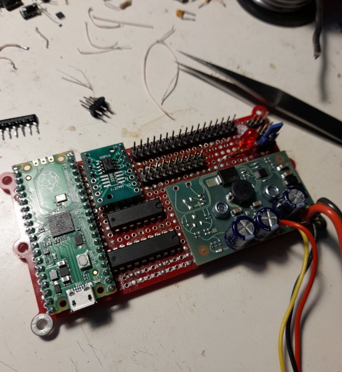
Then i write small PIO programm which calculates the cycles number between rising edges of MFM_Data signal:

.program sm_to_dma_to_buffer
start:
wait 0 pin 0 ; wait for a 0
wait 1 pin 0 ; wait for a 1, now we really have the rising edge
.wrap_target
mov x ~NULL ; start with the value 0xFFFFFFFF
timer_hp: ; loop for high period
jmp pin timer_hp ; test if the pin is still 1, if so, continue waiting
timer_lp: ; loop for low period
jmp pin timerstop ; if the pin has become 1, the period is over, stop count down
jmp x-- timer_lp ; if not: count down
jmp start ; timer has reached 0, stop count down of low period, restart
timerstop:
mov ISR ~x ; move the value ~x to the ISR: the low period (0xFFFFFFFF-x)
push noblock ; push the ISR into the Rx FIFO
.wrap
PiPico runnig at core clock 250MHz (set_sys_clock_khz(250000, false)), this is the maximum at which the USB virtual COM port connection to the computer continues to work.
I use DMA configured to 16-bit transfers from PIO to memory. When I enter the command to start capturing i am waiting INDEX signal low then high and then start PIO state machine:
pio_sm_exec(pio, sm0, pio_encode_wait_gpio(false, INDEX)); //wait 0
pio_sm_exec(pio, sm0, pio_encode_wait_gpio(true, INDEX)); // wait 1
// enable the sm
pio_sm_set_enabled(pio, sm0, true);
// let the dma channel do its stuff
dma_channel_wait_for_finish_blocking(dma_chan);
For now, I'm capturing all possible data (cycles between risign edges) from the beginning of the index pulse and end of memory array:
#define MAX_DELTAS 131072-4700 // maximum free memory on PiPico
uint16_t deltas[MAX_DELTAS];
For debugging, I use my old MFM hard drive NEC D3142 formatted on a AT 16-bit cirrus logic CL-SH260-15PC controller with the MS-DOS 5.0 operating system installed on it. I seek to 7 cylinder on it and transmit track data to host PC.
The main problem is that I can't decode the received data. I tried to apply your code "as is" to decode data based on functions:
static inline float filter(float v, float *delay)
int mfm_save_raw_word(int all_raw_bits_count, int int_bit_pos, int raw_word)
void MFM_Decode(int num_deltas)
but I get garbage instead of data at the output. This is understandable, since the distance between the fronts of the signal is measured in different units. But I don't understand how I can fix the values in the filter function (out = in * 0.034446428576716f + *delay * -0.034124999994713f;) and type constants float avg_bit_sep_time = 20; // 200 MHz clocks and avg_bit_sep_time = 20.0 + filter(clock_time, &filter_state);
Then I tried to apply the algorithm described here: http://www.pdp11gy.com/MFM-E.html , this particular program: http://pdp11gy.com/mfm/MFM_DECODER.txt And with this I saw a bit of data:
This is the best I have gotten so far. And I don’t even know what exactly the problem is - in the lack of speed in the PiPico PIO, in the skipping of pulses, in the decoding algorithm, or in something else.
I would be glad for any hints, maybe you will advise something. Just in case, I will attach the data I received from the 7 cylinder of my disk, which was partially decoded by the algorithm from the http://www.pdp11gy.com/MFM-E.html site and shown in the screenshot above.
Thank you very much in advance.
David Gesswein
Nov 25, 2022, 8:56:59 AM11/25/22
to mfm-d...@googlegroups.com
I think this code is measuring the time the MFM data line is low. You want
to measure the time between edges.
First look at a histogram of the transitions.
Here is an example from my emulator.
https://www.google.com/search?client=firefox-b-1-d&q=reseat+tire+bead+not+close+to+wheel#imgrc=2wtrZTUmlhASWM.
Its generated in my analyze.c
You should see three peaks at 200 ns (5 MHz), 300 ns, and 400 ns. With my
200 MHz sampling that's 40, 60, and 80 clocks. You should see a
reasonable width of near zero counts between the peaks.
If you sum the delta times between index pulses you should get close to
16.6666 ms (3600 RPM).
But I don't understand how I can fix the values in the
> filter function (out = in * 0.034446428576716f + *delay *
> -0.034124999994713f;)
>
These may not need changing. There were originally calculated based of filter
in a hard drive controller data sheet. They didn't work well so were hand
adjusted till they worked well.
and type constants float avg_bit_sep_time = 20; //
> 200 MHz clocks and avg_bit_sep_time = 20.0 + filter(clock_time,
> &filter_state);
>
20 should be your delta sample rate * 100 ns. The MFM edge timing is
theoretically integer multiples of 100 ns
Since your count loop is 2 cycles I think your sampling is effectively 125 MHz.
to measure the time between edges.
First look at a histogram of the transitions.
Here is an example from my emulator.
https://www.google.com/search?client=firefox-b-1-d&q=reseat+tire+bead+not+close+to+wheel#imgrc=2wtrZTUmlhASWM.
Its generated in my analyze.c
You should see three peaks at 200 ns (5 MHz), 300 ns, and 400 ns. With my
200 MHz sampling that's 40, 60, and 80 clocks. You should see a
reasonable width of near zero counts between the peaks.
If you sum the delta times between index pulses you should get close to
16.6666 ms (3600 RPM).
But I don't understand how I can fix the values in the
> filter function (out = in * 0.034446428576716f + *delay *
> -0.034124999994713f;)
>
in a hard drive controller data sheet. They didn't work well so were hand
adjusted till they worked well.
and type constants float avg_bit_sep_time = 20; //
> 200 MHz clocks and avg_bit_sep_time = 20.0 + filter(clock_time,
> &filter_state);
>
theoretically integer multiples of 100 ns
Since your count loop is 2 cycles I think your sampling is effectively 125 MHz.
> --
> You received this message because you are subscribed to the Google Groups "MFM Discuss" group.
> To unsubscribe from this group and stop receiving emails from it, send an email to mfm-discuss...@googlegroups.com.
> To view this discussion on the web visit https://groups.google.com/d/msgid/mfm-discuss/7583474c-dca2-40f0-b4d3-442e08c64816n%40googlegroups.com.
> You received this message because you are subscribed to the Google Groups "MFM Discuss" group.
> To unsubscribe from this group and stop receiving emails from it, send an email to mfm-discuss...@googlegroups.com.
tronix286
Nov 25, 2022, 9:45:26 AM11/25/22
to MFM Discuss
Thank you for your answer.
Unfortunately your link leads to a google query on the topic "reseat tire bead not close to wheel", not to example from your analyze.c. You probably just pasted the wrong link.
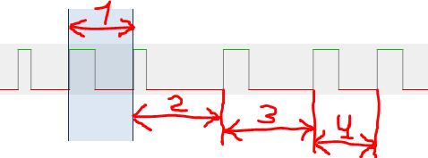
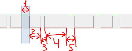
I'm a little confused how exactly I should count edges? I should measure delta time between front edges or i should measure delta time between all edges (rising and falling)? Could you suggest an option for these pictures?
(variant 1 - rising edges. This is how I think now implemented.)
(varian 2 - all edges - rising and falling)
Which variant should I use?
>20 should be your delta sample rate * 100 ns. The MFM edge timing is
>theoretically integer multiples of 100 ns
>
>Since your count loop is 2 cycles I think your sampling is effectively 125 MHz.
>theoretically integer multiples of 100 ns
>
>Since your count loop is 2 cycles I think your sampling is effectively 125 MHz.
If I understand correctly, then I should substitute the value 12.5 as avg_bit_sep_time constants, right?
Thanks!
пятница, 25 ноября 2022 г. в 16:56:59 UTC+3, d...@pdp8online.com:
David Gesswein
Nov 25, 2022, 10:47:37 AM11/25/22
to mfm-d...@googlegroups.com
On Fri, Nov 25, 2022 at 06:45:25AM -0800, tronix286 wrote:
> Unfortunately your link leads to a google query on the topic "reseat tire
> bead not close to wheel", not to example from your analyze.c. You probably
> just pasted the wrong link.
>
Correct link
> Unfortunately your link leads to a google query on the topic "reseat tire
> bead not close to wheel", not to example from your analyze.c. You probably
> just pasted the wrong link.
>
https://groups.google.com/g/mfm-discuss/c/kjKez8vfapU/m/4XamyQJgCAAJ
> (variant 1 - rising edges. This is how I think now implemented.)
>
loop. Could be not understanding how the code works. I would expect a decrement
in timer_hp. Timerstop and wrap_target will also loose 3 clocks so you may
need to compensate for that.
> >20 should be your delta sample rate * 100 ns. The MFM edge timing is
> >theoretically integer multiples of 100 ns
> >
> >Since your count loop is 2 cycles I think your sampling is effectively 125
> MHz.
>
> If I understand correctly, then I should substitute the value 12.5 as
> avg_bit_sep_time constants, right?
>
That is only used for creating emulation file when not decoding the data.
You need to fix code like this in the specific decoder such as wd_mfm_decoder.c
nominal_bit_sep_time = 200e6 /
mfm_controller_info[drive_params->controller].clk_rate_hz;
where 200e6 becomes 125e6.
tronix286
Nov 25, 2022, 12:51:27 PM11/25/22
to MFM Discuss
>Variant 1 is what I use. I only see x decremented in the pin low portion of the
>loop.
Yes, thank you very much, indeed I have a mistake here. I'm a beginner, sorry . Now I have rewritten the code like this:
.program sm_to_dma_to_buffer
start:
wait 0 pin 0 ; wait for a 0
wait 1 pin 0 ; wait for a 1, now we really have the rising edge
.wrap_target
mov x ~NULL ; start with the value 0xFFFFFFFF
timer_hp: ; loop for high period
jmp x-- test ; count down for pulse width
jmp start ; timer has reached 0, stop count down of pulse, restart
test:
jmp pin timer_hp ; test if the pin is still 1, if so, continue counting down
timer_lp: ; loop for low period
jmp pin timerstop ; if the pin has become 1, the period is over, stop count down
jmp x-- timer_lp ; if not: count down
jmp start ; timer has reached 0, stop count down of low period, restart
timerstop:
mov ISR ~x ; move the value ~x to the ISR: the low period (0xFFFFFFFF-x)
push noblock ; push the ISR into the Rx FIFO
.wrap
Unfortunately the counting takes many cycles, but I hope I am not missing pulses. I again capture 7 cylynder from my HDD, correct values for short-long-very_long pulses for MFM decoder program from pdp11gy.com site and get this:

Tomorrow I will try to make the code from wd_mfm_decoder.c works.
Thank you, David. You helped me a lot!
пятница, 25 ноября 2022 г. в 18:47:37 UTC+3, d...@pdp8online.com:
tronix286
Nov 26, 2022, 11:14:40 AM11/26/22
to MFM Discuss
Today I tried to apply the function wd_decode_track() but it pulled too many functions and dependencies from different files. I haven't been able to piece it all together yet.The fact is that I work in Windows in Visual C 2008 and some moments are too complicated for me. But I will keep trying.
I would like to understand - if I use the function mfm_decode_track_deltas from mfm_decoder.c and then save result fwrite(current_track_words, current_track_words_ndx, 4, fp); can I see some human-readable characters in it (for ex. MBR ot boot-sector messages)? Or due to the fact that there is no complete detailed parsing of the format, I should not see any human-readable string patterns there and I need to try to implement a full cycle of parsing the track with wd_decode_track() or other special decoder?
Because now I see just random values in the results and I can’t pick out a single human-readable word from them. At the same time, if I use the MFM decoder program from pdp11gy site, then I sometimes find fragments of words or whole words.
PS: I tried to build a histogram, this is what happened:
0, 0
1, 0
2, 0
3, 0
4, 0
5, 0
6, 0
7, 0
8, 0
9, 0
10, 0
11, 1
12, 0
13, 0
14, 0
15, 0
16, 0
17, 0
18, 2
19, 3
20, 4
21, 4
22, 5546
23, 38989
24, 19756
25, 3120
26, 37
27, 3
28, 4
29, 1
30, 1
31, 4
32, 5
33, 130
34, 9183
35, 26793
36, 12576
37, 501
38, 1
39, 1
40, 0
41, 0
42, 1
43, 1
44, 2
45, 0
46, 17
47, 1858
48, 5916
49, 1799
50, 80
51, 0
52, 0
53, 0
54, 0
55, 4
56, 2
57, 0
58, 0
59, 1
60, 1
61, 0
62, 3
63, 4
64, 2
65, 3
66, 0
67, 0
68, 0
69, 2
70, 0
71, 3
72, 1
73, 2
74, 2
75, 0
76, 1
77, 0
78, 0
79, 0
80, 0
81, 0
82, 2
83, 0
84, 0
85, 0
86, 0
87, 0
88, 0
89, 0
90, 0
91, 0
92, 0
93, 0
94, 0
95, 0
96, 0
97, 0
98, 0
99, 0
Primary transition period 186 ns, should be around 200
First two transition periods 186, 281 ns
PS2: Also i fixing my stupied error in define, it was
#define MAX_DELTAS 131072-4700
Became:
#define MAX_DELTAS (131072L-4700L)
Because of this, I sent only 131072-(4700*2) bytes to the host instead of (131072-4700)*2.
пятница, 25 ноября 2022 г. в 20:51:27 UTC+3, tronix286:
David Gesswein
Nov 27, 2022, 11:37:49 AM11/27/22
to mfm-d...@googlegroups.com
mfm_decode_track_deltas leaves the data still MFM encoded so you won't
see any text. You need to use wd_decode_track.
Histogram looks like the data should be recoverable. Assume peak is 23 vs
25 due to couple cycles lost in code setup. Should use 23 as
nominal_bit_sep_time.
> > <http://pdp11gy.com/mfm/MFM_DECODER.txt> program from pdp11gy.com site
see any text. You need to use wd_decode_track.
Histogram looks like the data should be recoverable. Assume peak is 23 vs
25 due to couple cycles lost in code setup. Should use 23 as
nominal_bit_sep_time.
> --
> You received this message because you are subscribed to the Google Groups "MFM Discuss" group.
> To unsubscribe from this group and stop receiving emails from it, send an email to mfm-discuss...@googlegroups.com.
> To view this discussion on the web visit https://groups.google.com/d/msgid/mfm-discuss/6ffa8740-04e1-4b66-bd91-14b108f97e5cn%40googlegroups.com.
> You received this message because you are subscribed to the Google Groups "MFM Discuss" group.
> To unsubscribe from this group and stop receiving emails from it, send an email to mfm-discuss...@googlegroups.com.
tronix286
Nov 27, 2022, 1:25:03 PM11/27/22
to MFM Discuss
Thanks for replay. Today I spent the whole day trying to build your project under mingw and get some progress. So far I have used a lot of dummy functions in board.c, drive.c, pru_setup.c, deltas_read.c and so on. I hardcoded load my file from Pico to deltas[] array at mfm_read startup. And finaly run it with this options: mfm_read -a=7,0 (because i grab cylinder 7 head 0 on Pico) and get this awesome output:
Primary transition period 186 ns, should be around 200
mfm_controller_info[drive_params->controller].clk_rate_hz;
...skip...
Vector4_ST506 not match 1 good 0
Checking Stride_440
Stride_440 not match 0 good 0
Checking Saga_Fox
Saga_Fox not match 1 good 0
Checking PERQ_T2
PERQ_T2 not match 1 good 0
[MY_DEBUG]: deltas_wait_read_finished
Checking Stride_440
Stride_440 not match 0 good 0
Checking Saga_Fox
Saga_Fox not match 1 good 0
Checking PERQ_T2
PERQ_T2 not match 1 good 0
[MY_DEBUG]: deltas_wait_read_finished
Primary transition period 186 ns, should be around 200
[MY_DEBUG]: exit rate
Matches count 20 for controller WD_1006
Header CRC: Polynomial 0x1021 length 16 initial value 0xffff
Sector length 512
Data CRC: Polynomial 0x140a0445 length 32 initial value 0xffffffff
Selected head 1 found 0, last good head found 0
Read errors trying to determine sector numbering, results may be in error
Number of heads 1 number of sectors 16 first sector 1
Interleave (not checked): 8 9 1 10 2 11 3 12 4 13 255 14 6 15 7 16
Drive still at track 0 after seek
Drive still at track 0 after seek
Drive is not seeking properly
>Histogram looks like the data should be recoverable. Assume peak is 23 vs
>25 due to couple cycles lost in code setup. Should use 23 as
>nominal_bit_sep_time.
>25 due to couple cycles lost in code setup. Should use 23 as
>nominal_bit_sep_time.
I have to do in all decoders like this:
nominal_bit_sep_time = 115e6 /mfm_controller_info[drive_params->controller].clk_rate_hz;
?
or 230e6 (230/10 = 23)?
And what about
max_delta = nominal_bit_sep_time * 22;
?
Thanks for your great project, it's really complex and without your support I wouldn't be able to do anything.
Little by little, I began to understand it.
воскресенье, 27 ноября 2022 г. в 19:37:49 UTC+3, d...@pdp8online.com:
David Gesswein
Nov 27, 2022, 2:14:08 PM11/27/22
to mfm-d...@googlegroups.com
mfm_util may be easier to start with. That is the standalone program intended
to be build on any Unix like system do doesn't depend on some of the files you
list. Looks like your close so may be too late to make sense switching.
On Sun, Nov 27, 2022 at 10:25:03AM -0800, tronix286 wrote:
>
> I have to do in all decoders like this:
> nominal_bit_sep_time = 115e6 /
> mfm_controller_info[drive_params->controller].clk_rate_hz;
> ?
I think this is correct.
> And what about
> max_delta = nominal_bit_sep_time * 22;
> ?
>
Should be ok. 22 is bits so doesn't depend on sample rate.
to be build on any Unix like system do doesn't depend on some of the files you
list. Looks like your close so may be too late to make sense switching.
On Sun, Nov 27, 2022 at 10:25:03AM -0800, tronix286 wrote:
>
> I have to do in all decoders like this:
> nominal_bit_sep_time = 115e6 /
> mfm_controller_info[drive_params->controller].clk_rate_hz;
> ?
> And what about
> max_delta = nominal_bit_sep_time * 22;
> ?
>
tronix286
Dec 9, 2022, 12:04:41 PM12/9/22
to MFM Discuss
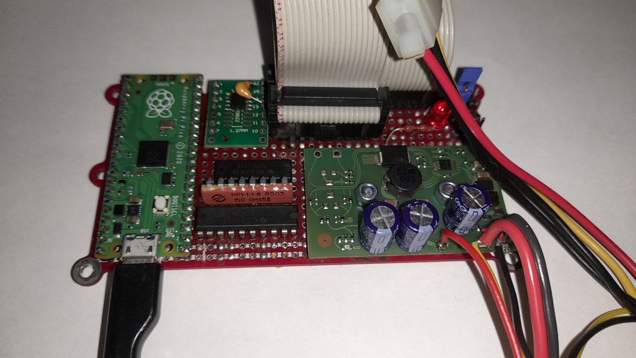
Thanks to David for supporting me. I think I got what I wanted.
I achieved stable pico operation at 400 MHz, since there were retrains and bad CRСs with a lower frequency.
Now I can 100% read my MFM hard drive from an IBM AT controller. The contents of the dump match the contents of the disk.
Now I can 100% read my MFM hard drive from an IBM AT controller. The contents of the dump match the contents of the disk.
Unfortunately, the disks from the flea market both turned out to be RLL and, apparently, they were formatted on the same controller before being sold, which means they do not contain any interesting information.
But on the other hand, I got a little acquainted with Pi Pico and now I have my own MFM disc reader.
Thank you!
воскресенье, 27 ноября 2022 г. в 22:14:08 UTC+3, d...@pdp8online.com:

Forgotten Machines
Dec 9, 2022, 8:50:27 PM12/9/22
to MFM Discuss
tronix286, VERY nicely done here, thanks for sharing!
Forgive me if you've specified this elsewhere, but do you intend to (or have you) share the plans (Pico code and circuit) for your creation on this project on GitHub or elsewhere? I'd like to potentially have a look at what you've done here, and give it a try myself. The PiPico is much more economical now than the Beaglebone Green, so this could be a very viable solution.
I use these devices a LOT, so having more build options would be very nice!
Thanks again for your great work on this, and as always, Thanks to David G. for his original plans and fantastic ongoing support!
Best,
AJ
tronix286
Dec 10, 2022, 3:25:46 AM12/10/22
to MFM Discuss
I did not plan to upload the project to the public domain because:
- It does not work quite the same as on the Beaglebone. He works worse. For a rough estimate of the contents of the disk, this is suitable, but for accurate dumping, I'm not sure;
- I'm a beginner in programming, so all pico code is "shit code";
- For the same reason, many crutches and hacks are included in David's original code. Only mfm_read tools compiled for Windows host PC.
I can draw a diagram and post it "as is" on github, but most likely you will have to edit something in the code yourself anyway and in the end you may not be satisfied with the stability of work. It seems to me that this is just a homemade craft for lack of the original Baglebone board.
суббота, 10 декабря 2022 г. в 04:50:27 UTC+3, mighty...@gmail.com:
tronix286
Dec 10, 2022, 7:08:46 AM12/10/22
to MFM Discuss
Just in case, posted "as is" here: https://github.com/Tronix286/MFM-Hard-Disk-Dumper
суббота, 10 декабря 2022 г. в 11:25:46 UTC+3, tronix286:
Forgotten Machines
Dec 11, 2022, 5:37:13 PM12/11/22
to MFM Discuss
tronix286,
Thank you for being willing to publish your code, and thank you for the disclaimers about it being very rough code. I fully understand and relate. I began publishing my data-capture programs on my own websites (before GitHub was popular), and it is equally rough...written very specific to my needs and applications. But yet, at least it is out there to be a springboard for the ambitious few who choose to glean value from the progress, and write their own "more polished" versions.
I suspect that what you have accomplished and published here bears many similarities to this. Thank you again, and well done!
Best
AJ
Reply all
Reply to author
Forward
0 new messages