Any Marlin pins and g-code for a electronics cooling fan?
1,085 views
Skip to first unread message

Alex
Nov 15, 2012, 1:03:00 PM11/15/12
to mend...@googlegroups.com
Are there any free pins the rams I can use to toggle a cooling fan for the electronics?
I'd like to put in start g-code and end g-code so it powers on and off with the print job?
I looked through the reprap wiki for the g-codes, and didn't see anything that looked like it will do this.
Any thoughts? If possible what pins and what code.
Thanks.

Misha
Nov 15, 2012, 1:16:57 PM11/15/12
to mend...@googlegroups.com
I have a fan hard wired to the power supply blowing over the electronics whenever the printer is on.
I was thinking of mounting a larger fan on the frame to quickly cool parts once the print is finished, so I'd be interested as well.

j...@250hacks.net
Nov 15, 2012, 1:21:07 PM11/15/12
to mend...@googlegroups.com
I have a fan hooked up to one of the
power outputs on my RAMPS (the "extra" power connector next to the
extruder and HPB connectors) and use g-code M106 Sxxx to turn it
on/off. Works like a champ.
Joe
Joe
--
Alex
Nov 15, 2012, 1:25:41 PM11/15/12
to mend...@googlegroups.com
Thanks Joe. That's what I'm using for parts cooling. I was hoping to have one independent but I guess I can use it if there are no other pins available for doing this.
Alex
Nov 15, 2012, 4:53:59 PM11/15/12
to mend...@googlegroups.com
M240 and a latching relay is the best I can come up with scanning Marlin_main.cpp

Larry Knopp
Nov 15, 2012, 5:36:17 PM11/15/12
to mend...@googlegroups.com
Bah.
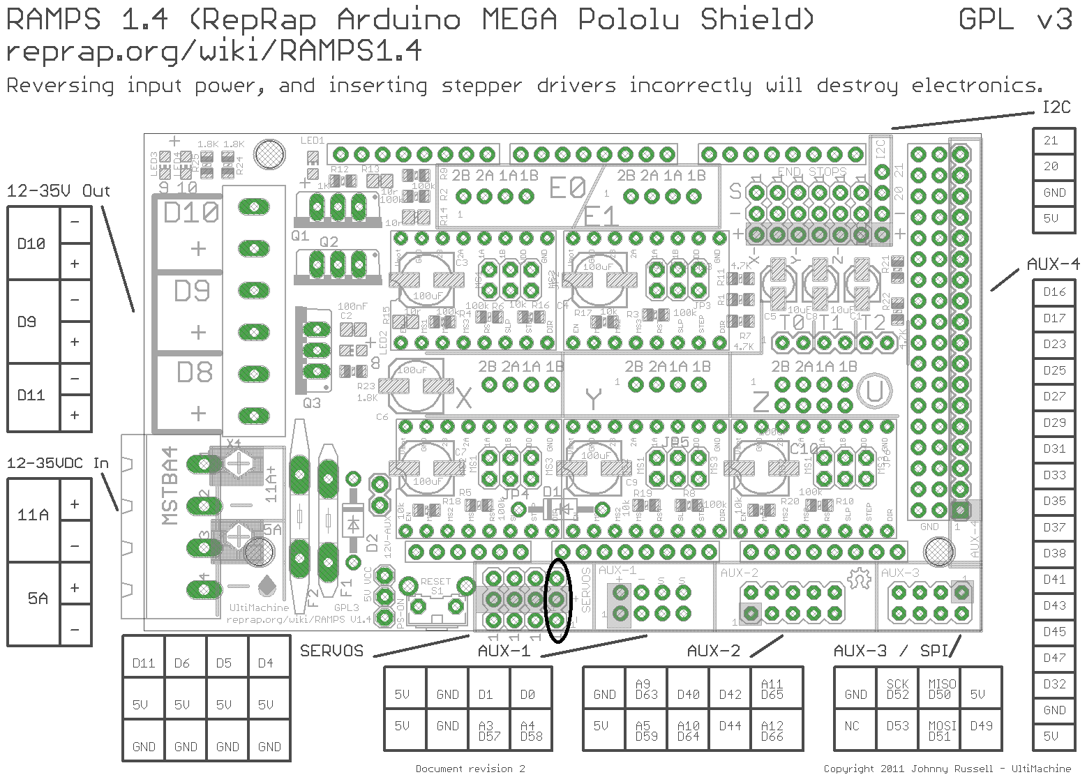
Attached diagram...
If you are not using any of the AUX headers...
Circled are the A4 pins in the servo block. 5V
Solder in a header. They are PWM'able.
Use the two outer pins.
Control via m42...
M42 P4 S255 = full on
M42 P4 S0 = full off
Profit.
;)
Attached diagram...
If you are not using any of the AUX headers...
Circled are the A4 pins in the servo block. 5V
Solder in a header. They are PWM'able.
Use the two outer pins.
Control via m42...
M42 P4 S255 = full on
M42 P4 S0 = full off
Profit.
;)
--

vlad
Nov 15, 2012, 8:40:05 PM11/15/12
to mend...@googlegroups.com
larry, that will be drawing 5 v from a digital pin you mean? Or did you leave out the tip of "solder a transiter/FET into the wire to be PWM @ 5v"

Triffid Hunter
Nov 16, 2012, 6:15:41 AM11/16/12
to mend...@googlegroups.com
On Fri, Nov 16, 2012 at 12:40 PM, vlad <vata...@gmail.com> wrote:
larry, that will be drawing 5 v from a digital pin you mean? Or did you leave out the tip of "solder a transiter/FET into the wire to be PWM @ 5v"
definitely mosfet.
If you're not sure which one to get, ramps comes with STP55NF06L as standard which is more than adequate for driving a fan.
My favourite is IRLB8743, however it's only rated to 30v and I have the supply on my Max dialed up to 28v which is much too close for comfort.. it would be fine for a fan since the fan only wants 12v, however it would also be complete overkill since according to the numbers in its datasheet, it can carry 15A with no heatsink; and I do know how to read a mosfet datasheet properly- that's a usable real-world number, not the fantasy they use to concoct the Ids(max) rating.
Alex
Nov 16, 2012, 9:13:01 AM11/16/12
to mend...@googlegroups.com
Double thank you.
According to your comment in the article, I should be able to drive the mosfet with a resistor rather than needed a mosfet driver in this schematic?
https://reipooom.files.wordpress.com/2011/09/mosfetexamplefixed2.jpg
Would you mind providing a schematic to drive a load with these pins and the mosfet?
Would you mind providing a schematic to drive a load with these pins and the mosfet?
Much appreciate it.
Alex
Nov 16, 2012, 9:14:00 AM11/16/12
to mend...@googlegroups.com
And thank you too Larry for pointing out the AUX pins
Larry Knopp
Nov 16, 2012, 9:43:05 AM11/16/12
to mend...@googlegroups.com
Okay...
I am going waaaaay out here, against the grain of those of you who I am 100% sure know way more about electronics than I do (or will)... but, I am *not* running a FET, resistor, nuthin'. I have a pair of 25mm 5v laptop fans direct wired to the A4 pins.
I use M42 to control the fans.
I have had it set up this way for months.
Somebody wanna explain/tell me why I am magically able to do this without burning down the house?
--

Ross Shannon
Nov 16, 2012, 9:55:58 AM11/16/12
to mend...@googlegroups.com
40mA per I/O pin is not a lot to play with - your fans must not draw much
--
vlad
Nov 16, 2012, 5:47:24 PM11/16/12
to mend...@googlegroups.com
I would throw in a FET if I were you. You should only draw 40mA max per pin, and no more than 200 mA total. Surprised it still works...
remember all those outputs draw a tiny amount of powerr tha does add up. then throw on two fans, surprised it works.
remember all those outputs draw a tiny amount of powerr tha does add up. then throw on two fans, surprised it works.
Triffid Hunter
Nov 16, 2012, 8:21:21 PM11/16/12
to mend...@googlegroups.com
On Sat, Nov 17, 2012 at 1:43 AM, Larry Knopp <lwk...@gmail.com> wrote:
Okay...
I am going waaaaay out here, against the grain of those of you who I am 100% sure know way more about electronics than I do (or will)... but, I am *not* running a FET, resistor, nuthin'. I have a pair of 25mm 5v laptop fans direct wired to the A4 pins.
I use M42 to control the fans.
I have had it set up this way for months.
Somebody wanna explain/tell me why I am magically able to do this without burning down the house?
The Atmel AVR series are very hardy and robust pieces of silicon. The outputs are current limited. A careful reading of the datasheet leads me to the conclusion that if the rated output current is exceeded, then the I/O pin is simply not guaranteed to obey VoH and VoL any more.
In other words, it's probably not supplying a full 5v to your fan. Lesser chips would have blown the output pin driver instead.
Driving it directly is definitely not recommended, only reason you're getting away with it is because AVRs are engineered very well ;)

md apu sarwar
Apr 10, 2018, 6:52:24 PM4/10/18
to MendelMax Support
Hi All,
I know this post are old, However, It would be great if you could answer the question below:
I would like to make dot printer:
I have XYZ axis and an amplifier to power the ink dropper.
- XYZ axis will move one step and stop. when it will stop on a location on that location it will deposit a drop of ink. so the ink dropper needs to power on via the amplifier connected to ramps 1.4 for 100 mili seconds to drop the ink on the surface. then powered of off the ink dropper. move the xyz to the next location and repeat the ink dropping.
- can anyone give G-Code for this operations.
please help.
Thanks
Reply all
Reply to author
Forward
0 new messages