PWM fan control not as nice as I'd like
788 views
Skip to first unread message

Greg. L
May 17, 2013, 7:30:22 PM5/17/13
to mend...@googlegroups.com
I've been working on a new fan/cooling assembly for my AO-101, and it's working fabulously. I've got two nice 60mm Sunon fans at skew lines on my cooling bed setting up a nice vortex and everything. I printed a single walled object with an edge so sharp I cut myself on it. Truly a sight to behold. And hold. To stop the bleeding.
The prototype iteration I've been running for the past few weeks was manual, with a nice DC control. The fans would startup at 2.5V, and go nicely up to 12V. I moved to RAMBO's on-board fan control this evening and was disappointed with the results. The PWM wouldn't start up until almost 210 (M106 S210), and going to S255 didn't have a noticeable effect.
I've got two theories.
1) It's simply not a smooth enough PWM to make things happy, and a nice 6.7mF capacitor in parallel with the fans should reduce the ripple down to 250mV and make it go.
2) The PWM on RAMBO is 10-bit, not 8-bit, and thus a setting of 210 is only 20% of the way into the range, which on a 12V system would be about, oh, 2.5V, making perfect sense. At the same time, the fan seems to be going quite fast at even that low setting and so empirically it doesn't make much sense.
Since I left my multimeter at work, I can't easily check voltages, so I thought I'd ping the group and see if anyone had any experience with this. Is a simple cap the fix, or is there something else? Any other suggestions? I'd really love to get this thing tidied up and put a bow on it, and the PWM just doesn't seem to be working as I'd hoped.

Larry Knopp
May 17, 2013, 9:49:11 PM5/17/13
to mend...@googlegroups.com
Huh.
I'll take a look at our bot with a RAMBO set up on it over the weekend. See what I can see.--
You received this message because you are subscribed to the Google Groups "MendelMax Support" group.
To unsubscribe from this group and stop receiving emails from it, send an email to mendelmax+...@googlegroups.com.
For more options, visit https://groups.google.com/groups/opt_out.

Russell Shipe
May 18, 2013, 8:28:31 AM5/18/13
to mend...@googlegroups.com
You may be discovering how hard it can be to control a inductive load by pwm. It doesn't seem to be too much trouble with little fans I don't know why... read up on lc tanks.. when you add a capacitor and get near a resonant frequency weird things happen things happen. You may need a fly by diode on the motor. Pretty much what happens is the when the power is on magnetic field builds in the coil of the motor then when power is turned off the field starts collapsing the inductance of the motor will not allow current flow to stop instantaniously so it 1) arcs out or 2) charges a cap which can be in parrellel or series with the motor. 3) gets shunted thru a fly by diode. At the just right (or for your application wrong) frequency the cap and inductor working together make the inductance of the motor effectively 0 so you can actually consume more real power (or maybe its apperent power) because you are modulating it not less.
Greg. L
May 18, 2013, 8:59:29 AM5/18/13
to mend...@googlegroups.com
Russell -
I've heard about this, but never seen it in practice - I always put flyback diodes on things, and don't yet have a capacitor in line to resonate. The only other place a cap could be is /in/ the fan, and I've admittedly heard of that - many fan manufacturers have a tiny bit of capacitance on the PCB inside the fan to keep things like the tach running nicely. More generally, I've controlled many much, much larger inductive loads via PWM (1KW motors) all the way down to 5W motors (just yesterday) and never had a problem.
That's why I'm so quick to blame the PWM generation on the RAMBO, or something strange about the fans. Given how responsive the RAMBO team has been, and looking at the schematics, there really aren't any places it should or could be 'wrong' other than the firmware, and if I'm the only one seeing it, I wonder if it's not the opposite of what you describe - the PWM duty cycle goes high, beginning to force the inductive load to accept current, and before the curve really goes anywhere, the driver shuts off again. That's why there's a certain point where it simply starts working - the duty period is high enough to let the inductor charge up, and then you get some torque, things start spinning, and away you go.
I should try that cap later this weekend, and then I'll go nose-deep in the firmware to see the PWM frequency, and if I'm feeling saucy, I think I might /drop/ it - to give the inductor a chance to charge up before the high period ends.
Russell Shipe
May 18, 2013, 9:15:46 AM5/18/13
to mend...@googlegroups.com
yea i know some big motors are controlled by PWM, (my lathe is a 1hp 750is watt pwm motor) i think the big controllers use a De "Qed' cap bank with filiters so that the PWM generations effectively a lower voltage dc instead of step AC . I think our PWM's are more targeted at fully resitive loads that dont care if we hit it with DC or step AC. also the use of words "Weird behavior'. because everything preforms normally untill you get close to the resonant frequency. i also know most little fans are made to be PWM controlled and have de'qing' diodes in them (why they dont spin backwards when you put power to them reverse polarity)
Also I am a mechinic and chemist by trade my knowledge of inductive kick comes from being shocked by it and not giving up till i understood why so its a skewed view...
i know it also maters what type of motor it is honestly i dont know what type of motor our fans use... ive always assumed its communtated dc but you know where that leads...

Last note DC motors have big time starting surges (gives us the big starting torque) my lathe with DC PWM control has a giant inductor in series with the motor, i assume this is to prevent the huge starting surge maybe it preforms some other function as well.
Here is a picture of things i would play with.
Greg. L
May 18, 2013, 1:39:06 PM5/18/13
to mend...@googlegroups.com
Ah, that might well be it. I hadn't even considered that they might be brushless, and that would explain things nicely. I figure a nice 1 Ohm, 1mF low pass filter ought to get me a nice low-ripple DC from the PWM - now I just need to get the components and try it out!
On Saturday, May 18, 2013 10:29:13 AM UTC-4, copperclad wrote:
On Saturday, May 18, 2013 10:29:13 AM UTC-4, copperclad wrote:
Hi
I know most of the little CPU cooling fans are labeled 12V DC , but it is my understanding that they are brushless motors . I haven't ever tried running them off a PWM controller , but I can see where they might behave oddly. HTH
best regards
Greg. L
May 18, 2013, 1:55:29 PM5/18/13
to mend...@googlegroups.com
Aha! According to Maxim (an electronics IC manufacturer that makes DC fan control chips):
"...Remember that these electronics were not designed to run on anything but DC supplies. Thus, useful (PWM) frequencies range from 20Hz to 160Hz."
Thus, DC filtering is one option, as is drastically reducing the PWM frequency on the board. My gut says that there's only going to be one PWM base frequency on the Atmel chip, so changing that would very much affect my thermistor PID loop. Still, I'm mentioning it for future readers who are searching this.
Larry Knopp
May 18, 2013, 4:32:38 PM5/18/13
to mend...@googlegroups.com
(great thread, guys... thanks!)
Still haven't gotten to my bot with the RAMBO on it (tomorrow), but iirc the fan I have on it is also of the brushless variety...--
Greg. L
May 20, 2013, 7:49:20 PM5/20/13
to mend...@googlegroups.com
Alrighty - so here goes.
The fans I have are brushless, and do require a nice smooth DC voltage to keep the onboard circuitry happy. A simple one-pole low-pass filter can help get this for me. As a first-order approximation, I wanted a filter with a cutoff frequency on or around 20Hz, as when I started, I believed that the RAMPS was doing a 20KHz PWM (Later thinking says that it isn't), and with a three-decade frequency difference, I'd expect a nice 50-60 dB reduction in signal, dropping any amplitude variation by about 500 or so. This would reduce a 6VDC + 6VAC signal (0-12V) to having only a 12mV voltage variation on top of the DC - pretty reasonable. Cutoff frequency is just 1/(2 * Pi * R* C), so RC needs to be on the order of 7.9E-3 ohm*farads.
The eventual goal, at full power, would be to drive a pair of 1.5 Watt fans, so at 12V (full voltage) I'd need 0.25A. Since all current has to go through the resistor in the low pass filter (hereafter LPF), power dissipation in the LPF will be I^2 * R = 0.0625 * R. For any reasonably 'high' value of R, that can be a pain. I don't want to dissipate more than 1W in my LPF, and frankly, would rather dissipate 0.5W so that I can use nice simple resistors. That leads me to a max of 8 Ohms, and a 1 milliFarad capacitor.
Then I realized that this isn't a traditional AC signal. The RAMBO schematics show that the fan is always connected to 12V, and the low-terminal is occasionally connected to ground via the PWM-driven NFET. Thus, it's essentially open-collector, and traditional AC math doesn't quite cut it. In particular, without the driver pulling down as well as up, the technical DC signal is something /like/ 12V anyway. Thus, the concern is that the system is only ever pulled one way, so you don't get a nice average like you'd hope for with a square wave. Instead, the voltage across the cap only gets pulled up by the driver, and only pulled down by the fan.
Setting up a steady-state KCL, at the capacitor, i_Rfilter = i_Fan
i_Rfilter = percent_on * (12 - V_fan)/R_filter
i_Fan = V_fan/R_fan
Setting the two equal, I eventually find...
V_fan = 12 * percent * R_fan / (R_filter + percent * R_fan)
R_fan is approximately 48 Ohms (assuming it's linear, which I'm not sure of, but it'll do), and assuming R_filter is 8 Ohms (from above)...
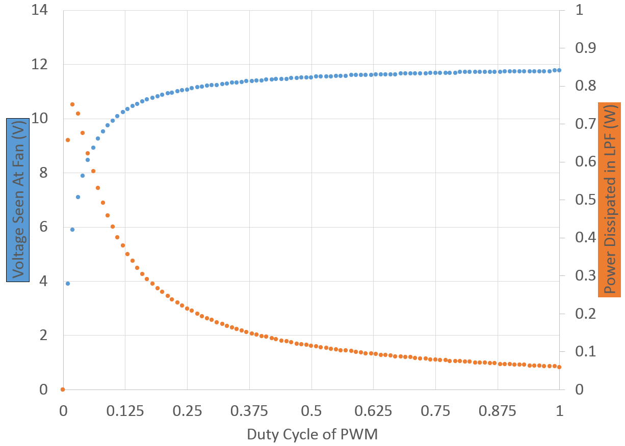
What we see is that the 8 Ohm resistor in the LPF does reduce the maximum potential of the fans, which can no longer see 12V, even in the best case. More interestingly, the relationship between voltage at the fans and the duty cycle is nonlinear by a large margin. Finally, we note that power dissipated in the LPF is higher than we might have realized at first glance - while the current at high duty cycles does give the fairly low power dissipation we were hoping for, at lower duty cycles there's more of a voltage drop across the filter, leading to higher currents rushing through it, struggling to keep that cap charged. Thus, the 8 Ohm resistor burns what I consider to be too much power.
Resolving the system, then, for various values of filter resistor doesn't really help that much - I keep getting dissipation peaks on the order of 0.8 Watts.

Going with a higher resistor, then, has two benefits:
1) It pushes the exponential farther to the right, looking more and more linear.
2) To get the time constant needed (8 ms), you can use ever-smaller capacitors, and since 1mF caps are fairly large, that's helpful.
The downsides, then, are:
1) General power dissipation. While peaks are near 0.8W for many to most configurations, higher resistor values reach them more often, and more consistently.
2) Peak voltage. Since larger filter resistors essentially make a voltage divider with the load, your peak voltage drops off for the fan. Luckily, most fans work equally well (or too well) at 12V anyway, so this isn't a huge issue.
Currently, I've got a 1 Ohm 5W resistor with a 4mF cap on my system, and my fans do nice things, but due to the non-linearity between duty cycle and fan voltage, my fans turn on at only a 6% duty cycle, and hit near-max flow at only 35% duty cycle. Thus, I set my slic3r fan min to 6%, and max to 35%, giving me the closest to linear I can get.
If I were to buy components again, I'd likely go with a 20 Ohm 5 Watt resistor, and a 400uF cap. Much smaller, and it would likely give me better linearity, and I won't miss the top end of the fans, which I'm not using anyway.

Does anyone see anything I missed? Anything I flubbed up like a bad person? Either way, I hope it at least kept your interest...

temo
May 21, 2013, 9:51:09 AM5/21/13
to mend...@googlegroups.com
Hello Greg
Do you have a photo to show where you have placed the fans?
What are pros and cons of placing them to blow in from the sides/from above?
Should they rise with the x-carriage
Terje
Reply all
Reply to author
Forward
0 new messages