High voltage/current board

1,094 views
Skip to first unread message

Pablo Vila Ferrero

unread,
Mar 3, 2017, 1:37:35 PM3/3/17
to Mechaduino

Since I discovered Mechaduino while looking about info of absolute encoders, for a BLDC servodrive I'm working on, I thought it was an awsome project. While the

hardest part is done (programming), it's a shame that the boards are so limited in power. I come from the world of DIY CNC machines and they usually need way more

powerfull steppers than NEMA 17 (although I have one that works with them but is very small), or low power NEMA 23, than 3D printers if you don't want be stalling the

motors or loosing steps all the time.

Most people would think that the weakest point of this drive is the low amperage. Since torque is proportional to amperage, when people start loosing steps while they

rise the speed of theirs motors, they try to fight it by increasing the amps, but they sould be increasing the voltage. Happens that because of the high impedance of

the steppers motor, the back EMF limits the amount of current that the motors can get. For example I tried the other day to increase the voltage of my steppers drive

of my milling machine from 48V to 67V. I use NEMA 24 motors and I could get 3000mm/min in the headstock (around 60kg) at 48V, increasing it to 67V I could get it twice

as fast, 6000mm/min:


So to improve more the performance I'm thinking on installing new drives based on the Mechaduino, but I will need a new power section. My goal is to make a discrete

MOSFET version, compatible with the Mechaduino software, encoder and Arduino Zero/SAMD21 MCU. In fact, I was working to get my software working with Arduino DUE but,

since the Mechaduino software for steppers can be modified for 3 phase BLDC, I changed my mind.

I have selected N-channel IRF740 MOSFET. They are high dV/dt, 400V, 10A MOSFETs. To drive the high side of the H-bridge with N-channel MOSFET I will use a couple of IR

2101 MOSFET drives per H-bridge. Also, to get the same kind of input that the A4954 drive has, I will use a couple of 2 input AND gates, that will mix the PWM signal

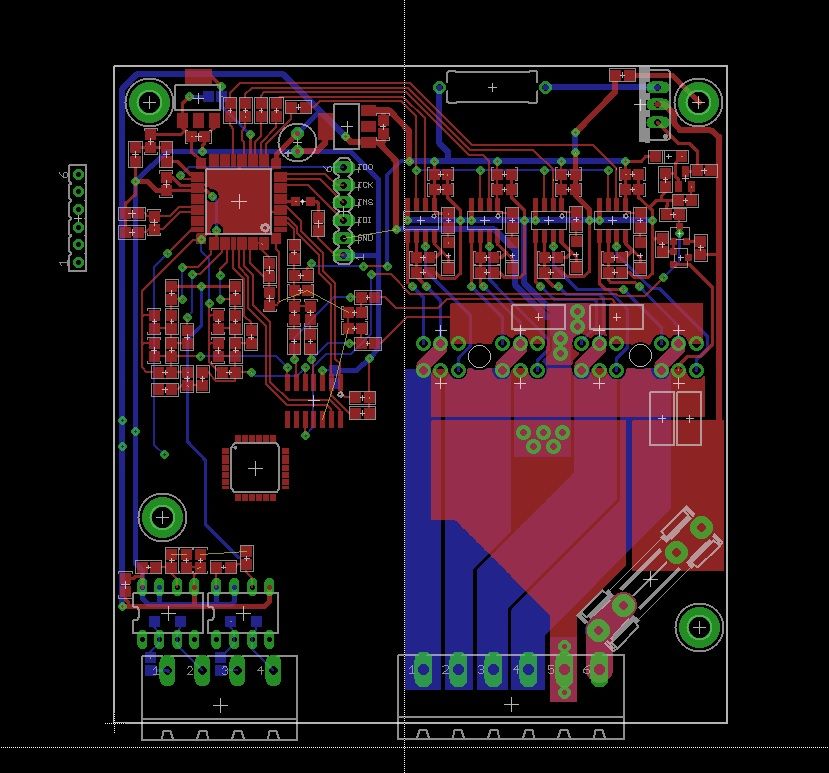
of each coil, with the signal that determines the direction of the current. This is the scheme of the H-bridge I'm working on (of course the drive will need two of

them):


Well, as you can see I have not selected any value yet on C1 and C2. That is because that are the capacitors that activates the high side of the H-bridge, since the MOSFET are N-channel. They will fill up when the MOSFET is OFF, and then use their energy to activate the MOSFET. That means that this bridge should always be controlled by a PWM signal that never goes 100% ON or they won't fill up. They must have enough capacity to mantain the MOSFET ON during the PWM cycle, but not too big or they won't fill up during the OFF time. Also this value depends on the PWM frecuency, higher frecuencies need smallers values of the capacitors. On the circuit I got the idea they used 2.2uF, but I haven't got any luck getting it working (with ATMEGA 34U4). In other web they recomend values between 4.7uF and 22uF for 50kHz, so I will try different values to find the best one, aiming for 80%-90% PWM ON time. This design don't have any current limiting, so precautions need to be taken to avoid burning the motor or MOSFETs.

I'm not an expert on hardware or electronics so any help, advice, idea or recomendation on the design will be very apreciated!

Trampas Stern

unread,
Mar 3, 2017, 3:48:33 PM3/3/17
to Mechaduino
I have been working on a NEMA 23 form factor board with discrete drivers.  I am using the BUK9K13-60E FETs at the moment which are 60V 40A units, I figured to limit voltage to 48V. 

I have ordered my 4th prototype PCB and have learned a few lessons... 

First PCB:
The lesson learned here is that measuring the current using a sense resistor is on the ground of the H-bridge is difficult as that you have to have some delay time after turning on motor before measurement of current, often called blanking time in driver datasheets. The A4954 has around 3us of blanking time. What this means is that power is always on for at least 3us, then you can ramp down or turn off.  This can cause some problems, for example see this blog post. 

Second PCB:
I used a current sensor for each coil. This design works but the voltage was limited to 24VDC, additionally I found that trying to do the mix decay in firmware was very taxing on the processor resources. Additionally the SAMD21 does not have the fastest ADC 350Ksps which is shared across all the ADC channels so doing two ADCs is limited in best case to 175ksps, which means 5us time for doing current measurements.  I worked around some of these problems for example on power up I measure the current verse PWM time such that I do not have to ADC. For the decay mode I take a hit in my processing loop and do a fix fast decay time followed by slow decay.  This all worked but I wanted higher voltage, and better control over the current.  I also wanted to measure motor voltage to detect capacitance change. 

Third PCB:
After talking with Atmel FAE, they recommended the SAMS70 in the 64 pin TQFP which is a 300Mhz part with hardware double precision math.  This sounded great, but they informed me that that the USB only worked at full speed, not the high speed in the 64 pin package.  This was not a problem as we just use as serial port. I got boards back and was about to populate last week when they told me that the USB did not work at all on the 64 pin part....  So trashed PCBs without ever populating one, talk about expensive.... 

Fourth PCB:
These are arriving next week and have a 100 pin TQFP SAMS70.  I am currently working on trying to port the SAMS70 to the Arduino IDE, but have ran into many bugs. For example Atmel has no examples for the SAMS70 chip, the parent chip, SAMV71, has examples but even their  CDC USB driver did not work, so it has been slow and painful trying to get the chip up and running. I am not making progress and will continue the work.  I suspect that the first version of the firmware might not be support in Arduino IDE but will get there. 

Back to your circuit... 
C1 and C2 are the charge pump capacitor for generating the high voltage on the positive side N-fet of h-bridge.  Like you have said picking the right value is dependent on the PWM frequency and duty cycle.  The circuit should still work, but the positive N-FET will get hotter and you will not have full voltage on motor, the FET will be in linear region as opposed to fully on.  Another thing is to be careful about the dead time on each H-bridge, not sure if the IR2101 handles this for you or not.  Also if you put a diode across your 20 ohm resistors it will allow the discharge of the FETs to happen quicker than the charging, this often helps reduce ringing when turning FETs off.  Also you have no means to measure the motor current in your circuit as such you will have to calibrate the PWM for each motor and driver voltage externally.  Also be careful with the AND gate, when the PWM is low HIN and LIN are low, this most likely floats the motor, which will put all the flyback current and voltage across the body diodes of the FET and they might not handle this. Therefore you might want to look more at slow and fast decay modes in drivers like the A4954, in the fast decay they reverse the FETs (try to drive coil backwards) this means the FET body diodes are only conducting during dead band time. While on slow decay they turn both low side FETs on to short out the motor, again body diodes only on during dead band time.  


Here is model of the boards with the 100 pin TQFP. 


The 3D model of the capacitors show 25V parts but I am using higher voltage rate caps with lower capacitance that are same form factor. 


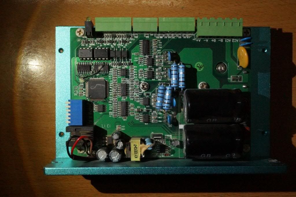
There are few changes from the Nano Zero Stepper (NEMA 17 board, www.misfittech.net):

1. The logic voltage is generated from the motor power supply, no need for external powering of the board. 

2. The addition of enable pin, and all logic pins on the green connector has level shifting, even the UART pins. 

3. 300Mhz cortex-M7 with hardware double precision floating point. 

4. High Speed USB, not sure what to use for but someone will have an idea. 

5. Of course high current with the ~10mOhm FETs, which should have little heating of board. 

6. Support for 48V, not the 67V you would like but it is a start. 


There are a lot of parts on this board and it is tough to even get the trace width wide enough to support 10A, much less heat sinks and trace and space to support 2oz copper. 


Trampas


Trampas Stern

unread,
Mar 3, 2017, 3:49:44 PM3/3/17
to Mechaduino
here is blog post on the blanking time problems:


Trampas

Cristian Nicola

unread,
Mar 4, 2017, 3:26:08 AM3/4/17
to Mechaduino
Hi Trampas,

Have you considered one of the many stm32s?

Kind regards,
Chris

Trampas Stern

unread,
Mar 4, 2017, 6:48:44 AM3/4/17
to Mechaduino
I am more these days.... 

Trampas

pa...@strotten.co.uk

unread,
Mar 5, 2017, 4:35:48 AM3/5/17
to Mechaduino
Pleade do you have the code for BLDC servo drive or info.
Many thanks Paul

Trampas Stern

unread,
Mar 5, 2017, 11:06:03 AM3/5/17
to Mechaduino
I have not done a BLDC servo yet. 

I have looked at BLDC motors but compared to cost of a stepper motor they are 10x as much. 

Trampas
Message has been deleted

Ti Voi

unread,
Mar 6, 2017, 5:46:05 AM3/6/17
to Mechaduino
i thinks , use mechaduino code with current control by CPLD is good choice

Ti Voi

unread,
Mar 6, 2017, 5:52:11 AM3/6/17
to Mechaduino
leadshine HBS drive use tms320f28035, only 60mhz, FOC closed loop


Trampas Stern

unread,
Mar 6, 2017, 7:08:49 AM3/6/17
to Mechaduino
I would love a CPLD version, if you are interested in making one let me know and I will help. 

Thanks
Trampas

Ti Voi

unread,
Mar 6, 2017, 8:32:52 AM3/6/17
to Mechaduino
i'm trying download mechaduino code with atme ice then build CPLD current control


Trampas Stern

unread,
Mar 6, 2017, 9:44:45 AM3/6/17
to Mechaduino
Are you going to uses a discrete driver circuit? 

Trampas

Ti Voi

unread,
Mar 6, 2017, 9:49:01 AM3/6/17
to Mechaduino
yes, i use xc9536+lm339 for chopper and ir2014+irf540

Trampas Stern

unread,
Mar 6, 2017, 10:20:34 AM3/6/17
to Mechaduino
How far along are you? 

What is your blanking time?  

How are you handling the fast verse slow decay modes? 

Ti Voi

unread,
Mar 6, 2017, 6:09:09 PM3/6/17
to Mechaduino
blanking time 3us, fix fequency pwm dont need slow decay

Trampas Stern

unread,
Mar 6, 2017, 7:29:19 PM3/6/17
to Mechaduino
You using fast decay only?

Ti Voi

unread,
Mar 6, 2017, 11:31:40 PM3/6/17
to Mechaduino

Ti Voi

unread,
Mar 7, 2017, 5:20:41 AM3/7/17
to Mechaduino
hi Trampas, how i can generator hex file from arduino IDE

Trampas Stern

unread,
Mar 7, 2017, 6:29:58 AM3/7/17
to Mechaduino
the following link has information about hex file
https://forum.arduino.cc/index.php?topic=131655.0

Also you can export the compiled binary using the Sketch menu option. 

Trampas
Message has been deleted

sup...@nhatsonelec.com

unread,
Mar 7, 2017, 8:59:00 AM3/7/17
to Mechaduino
thanks you Trampass
verilog microstepping code, we can mod it for current control
this is tutorial from Mariss , geckodrive

Ti Voi

unread,
Mar 9, 2017, 7:14:02 AM3/9/17
to Mechaduino
i was program chip with jlink and mechaduino code
how i can conect computer with board?

Ti Voi

unread,
Mar 9, 2017, 7:27:40 AM3/9/17
to Mechaduino
i trying layout mechaduino with cpld + discret hbridge


Ti Voi

unread,
Mar 10, 2017, 5:49:14 AM3/10/17
to Mechaduino
i was success upload program in to atsamd21g18
step 1, i program it with arduino M0 bootload ,download from here

then, reconect usb, computer detec it, we can direct upload mechaduino code from arduino

Trampas Stern

unread,
Mar 10, 2017, 5:58:08 AM3/10/17
to Mechaduino
sorry I thought you knew that... 

Trampas

Ti Voi

unread,
Mar 10, 2017, 6:12:03 AM3/10/17
to Mechaduino
thanks trampas, this is frist time i use arduino :)

Ti Voi

unread,
Mar 10, 2017, 6:15:58 AM3/10/17
to Mechaduino
next step, i try replace as5047d by as5147p

Lamont Cranston

unread,
Mar 11, 2017, 10:34:37 AM3/11/17
to Mechaduino

On Friday, March 10, 2017 at 3:15:58 AM UTC-8, Ti Voi wrote:
next step, i try replace as5047d by as5147p

Wow, is the AS5147P a new chip?  I had not heard of it before.

It looks like AMS makes their own Smart Stepper board now too:


Message has been deleted

Cristian Nicola

unread,
Mar 11, 2017, 11:20:17 AM3/11/17
to Mechaduino
It is just an adapter pcb for the sensor to be mounted on the nema motor. Dont think that would qualify as smart :)

AS5147P it is the same as AS5047 as far as i know, except for it is automotive grade rated (AEC-Q100). But i could be wrong...

Chris

Ti Voi

unread,
Mar 11, 2017, 11:39:23 PM3/11/17
to Mechaduino
i have this board, i check datasheet, it same register with as5047d
http://www.mouser.com/ds/2/588/AS5147P-TS_EK_AB_Operation-Manual_Rev.1.0-948139.pdf


Pablo Vila Ferrero

unread,
Mar 12, 2017, 12:03:16 PM3/12/17
to Mechaduino
Thanks for the info guys. I was aware of the MOSFET discharging diodes but forgot to add them, thanks for remembering that.

About the decay modes, I don't think they are gonna matter on this system, since is not a chopper drive. Decay modes are usually important in low quality chopper drives, where the resonances are not well balanced. A great solution is to increase the microstepping, I had never had a resonance problem with my stepper drives.

I keep working on my board but I don't have almost free time nowadays. Also is my first time working with Eagle. This week the microcontroller arrived, is a Robodyn SAMD21 MINI. I uploaded the Mechaduino program to the board to see if I could see the menus in the serial monitor but seems not to be working. Any idea why?
Message has been deleted

Pablo Vila Ferrero

unread,
Jun 19, 2017, 2:39:14 PM6/19/17
to Mechaduino
After a few back and fowards with my design, I made a couple of boards to test it. Here are them showing both sides:


I'm looking for ideas of new functionalities I can add to the hardware. I'm thinking on:

+Enable pin
+Error pin
+Actual current measuring of both coils
+Motor temperature measurement
+Breakout board of A/B/Index pins of the encoder

If anyone have an idea I can add to the hardware, feel free to post it!

Trampas Stern

unread,
Jun 20, 2017, 6:38:04 AM6/20/17
to Mechaduino
The Smart Steppers from Misfit Tech (www.misfittech.net) has some of the features including:

1. Error Pin
2. Enable Pin

The actual current measurement of both coils is done by the A4954, it gets a bit tricky to do additional current measurement.  Also if you measured the current it may not help you as that the A4954 measures and controls the current already, specifically the processor sets a voltage which is proportional to the desired current out of the A4954, so the only reason to measure current would be to determine if the A4954 was not in control. 

Motor temperature could be done, but usually this is not needed as the firmware on the devices will minimize the current to the motor and heat.  When the motor is in the correct position the board will lower current to keep motors quiet and cool. 

You could make a break out board with just encoder and have the A/B/index pins, but I would assume this would be for something else to control motor? 

Trampas

Pablo Vila Ferrero

unread,
Jun 20, 2017, 1:11:48 PM6/20/17
to Mechaduino
This board don't uses the A4954 driver, instead it uses 8 MOSFETs in 2 H-bridge configuration. The drivers will work as a chopper type, limiting the current. Current is limited by comparing the voltaje drop through a 0.1ohm resistor with an operational amplier vs a voltage set by the microcontroller. This is how the mechaduino works, but if the speed is high enough, the motor inductance wont let you have all the current, and your microcontroller won't know the real torque. Also it can be usefull to implement other control methods for the motor or maybe somebody need to have this data output by the USB.

Although the driver lets you control the max current through the motor, the stepper motor max current rating is for continuous working. You can actually set the max current in your driver higher than your motor rating and get faster acelerations and bigger torque. But this way, if your motor get stuck, by what ever external reason, it will overheat. By measuring the motor temperature you can actívate an error signal that will shut up the driver. Today I've been thinking that measuring the driver temperature can be also usefull to avoid burning it.

The A/B/Index breakout board is because the controller software I use on my machines needs a quadrature signal with index to perform rigid tappinig. The mechaduino is a servo so that is not really necesary, but if somebody is using the stepper as spindle motor, changing the machine configuration each time is quite a hassle.

LIN MA

unread,
May 15, 2018, 1:48:16 AM5/15/18
to Mechaduino
可以考虑使用ASMD51G18A芯片

LIN MA

unread,
May 15, 2018, 1:52:16 AM5/15/18
to Mechaduino
和MAIIL: 7945...@qq.com

与作者沟通非常荣幸
57闭环驱动器A.png
57闭环驱动器B.png
57闭环驱动器C.png
20180312_151807.jpg

gokul gaags

unread,
Apr 14, 2019, 10:56:36 AM4/14/19
to Mechaduino
I am working on my own mechaduino,i am having a doubt that can i use AS5047P instead of AS5047D and does it really matter on size of the magnet or can i use any size of the magnet.can i use any other stepper driver than A4954...
i am going to use SAMD21G18A....... and if i need to use any other then please guide me
it will be grateful if any one help me

Trampas Stern

unread,
Apr 17, 2019, 8:30:43 AM4/17/19
to Mechaduino
From a quick look the AS5047P looks like it will work fine. 

Check out MisfitTech.net as the NEMA23 board has a higher current driver.  

I am also looking at doing a discrete driver for a new board which will support up to 60V and 10A. 

Trampas
Reply all
Reply to author
Forward
0 new messages