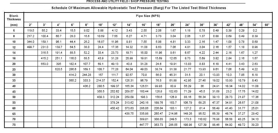
Blind thickness design

anishdev
Dear all,
Can someone help me to calculate the blind flange thickness for hydrostatic testing.
Thanks and Regards
Anish Dev.S
Gulf East Engg
Qatar

anas k
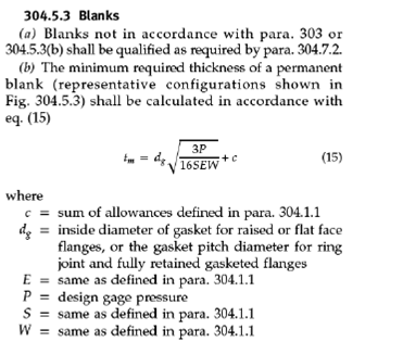
(AS PER ASME BOILER AND PRESSURE VESSEL CODE / VIII DIV I)
The blind flange is attached by bolts causing an edge moment (Fig. UG- 34. /sketch j) in which the thickness can be calculated by :
t = d *(CP/SE+1.9W hg/SE*d^3) ½ ……………….Formula (2) (From ASME UG-34)
Where,
d= Diameter or short span, measured as indicated in Fig. UG-34
E= Joint efficiency, from Table UW-12, of any category A weld as defined in UG-
3(a)
S= Maximum allowable stress value in tension from applicable table of value
Referenced by UG-23
W= Total bolt load (From pipe data pro)
hg= Gasket moment arm, equal to the radial distance from the centerline of the
bolts to the line of the gasket reaction, Table 2-5.2
P = Design pressure-HYDROTEST pressure is considered (13.5 bar (g))
C = 0.3 From Fig UG-34(j)
THICKNESS CALCULATION FOR THE 32” BLIND FLANGE :
Using the above formula (2)
t = d *(CP/SE+1.9W hg/SE*d^3) ½ ……………….formula (2) (from ASME UG 34)
d= 876.5 mm
C= 0.3
P = 13.76 kg/sq cm
E = 1
W = 94 KG
hg= 50.75 mm
S = 25 ksi = 1757 kg/sq.cm
Substituting the above values in Formula (2),
t = 876.5*[(0.3*13.76/1757*1) + (1.9*94*98)/ (1757*1*876.5^3)] ½
= 42.48mm or 42.5 mm
Therefore from the above calculation, the minimum thickness required for the 32” blind flange is :
t = 42.48 mm
THICKNESS CALCULATION FOR THE 36” BLIND FLANGE :
Using the above formula (2)
t = d *(CP/SE+1.9W hg/SE*d^3) ½ ……………….formula (2) (from ASME UG 34)
d= 978.2 mm
C= 0.3
P = 13.76 kg/sq cm
E = 1
W = 117 KG
hg= 53.25 mm
S = 25 ksi = 1757 kg/sq.cm
Substituting the above values in Formula (2),
t = 978.2*[(0.3*13.76/1757*1) + (1.9*117*98)/ (1757*1*978.2^3)] ½
= 47.41mm or 47.5 mm
Therefore from the above calculation, the minimum thickness required for the 36” blind flange is :
t = 47.41 mm
THICKNESS CALCULATION FOR THE 38” BLIND FLANGE :
Using the above formula (2)
t = d *(CP/SE+1.9W hg/SE*d^3) ½ ……………….formula (2) (from ASME UG 34)
d= 1038 mm
C= 0.3
P = 13.76 kg/sq cm
E = 1
W = 132 KG
hg= 55.5 mm
S = 25 ksi = 1757 kg/sq.cm
Substituting the above values in Formula (2),
t = 1038*[(0.3*13.76/1757*1) + (1.9*132*98)/ (1757*1*1038^3)] ½
= 50.31mm or 50.5 mm
Therefore from the above calculation, the minimum thickness required for the 38” blind flange is :
t = 50.31 mm
THICKNESS CALCULATION FOR THE 44” BLIND FLANGE :
Using the above formula (2)
t = d *(CP/SE+1.9W hg/SE*d^3) ½ ……………….formula (2) (from ASME UG 34)
d= 1118 mm
C= 0.3
P = 13.76 kg/sq cm
E = 1
W = 178 KG
hg= 98 mm
S = 25 ksi = 1757 kg/sq.cm
Substituting the above values in Formula (2),
t = 1118*[(0.3*13.76/1757*1) + (1.9*178*98)/ (1757*1*1118^3)] ½
= 54.19 mm
Therefore from the above calculation, the minimum thickness required for the 44” blind flange is :
t = 54.19 mm
THICKNESS CALCULATION FOR THE 46” BLIND FLANGE :
Using the above formula (2)
t = d *(CP/SE+1.9W hg/SE*d^3) ½ ……………….formula (2) (from ASME UG 34)
d= 1168 mm
C= 0.3
P = 13.76 kg/sq cm
E = 1
W = 180 KG
hg= 98.5 mm
S = 25 ksi = 1757 kg/sq.cm
Substituting the above values in Formula (2),
t = 1168*[(0.3*13.76/1757*1) + (1.9*180*98.5)/ (1757*1*11168^3)] ½
= 57 mm
Therefore from the above calculation, the minimum thickness required for the 46” blind flange is :
t = 57 mm
THICKNESS CALCULATION FOR THE 48” BLIND FLANGE :
Using the above formula (2)
t= d *(CP/SE+1.9W hg/SE*d^3) ½ ……………….formula (2) (from ASME UG 34)
d= 1219 mm
C= 0.3
P = 13.76 kg/sq cm
E = 1
W = 202 KG
hg= 101.5 mm
S = 25 ksi = 1757 kg/sq.cm
Substituting the above values in Formula (2),
t = 1219*[(0.3*13.76/1757*1) + (1.9*202*101.5)/ (1757*1*1219^3)] ½
= 59.09 = 59 mm
Therefore from the above calculation, the minimum thickness required for the 48” blind flange is :
t = 59 mm
Conclusion:
Since from the above calculation, 50 mm plate thickness required for the 32”, 36” & 38” with stress ration as 1.0
And 60mm thick plate is required for 44”, 46”, 48” blind flanges at 13.5 bar (g) hydro test pressure and at ambient temperature.
However if the thickness of the blind flange is less than required then additional reinforcements or stiffeners has to be provided.
--
To post to this group, send email to material...@googlegroups.com
To unsubscribe from this group, send email to materials-weld...@googlegroups.com
For more options, visit this group's bolg at http://materials-welding.blogspot.com/
The views expressed/exchnaged in this group are members personel views and meant for educational purposes only, Users must take their own decisions w.r.t. applicable code/standard/contract documents.


santhosh kumar
The Blind flange is selected based on the dia of the nozzle nozzle,
hydro pressure.But if you dont know, use blind flange thickness
equivalent to attachment flange thickness(not neck thk).
Regards
Santhosh
Phumpong Pong-im
Pls. use this one.
Best Regards,
PpP
(Phumpong P)
FE QA Ext. 5455404,
C/P 5456000 Ext.1490 , 0818440563
From: material...@googlegroups.com [mailto:material...@googlegroups.com] On Behalf Of anishdev
Sent: Tuesday, February 14, 2012 1:22 AM
To: material...@googlegroups.com
Subject: [MW:13665] Blind thickness design
Dear all,
--
manpreet
Nobody would be able to answer this unless required information is provided, Which Class,
Material, Size, pressure and temperature...
Please refer ASME B16.5, you will note that Table 22 has maximum size listed as 12" for #2500.
For all other Classes (upto #1500) maximum size is listed as 24".
If your design criteria falls within ASME B16.5 range then Simply Purchase Blind Flange in
accordance with ASME B16.5.
If not then refer ASME Sec Viii Div 1 UG-34 to calculate Blind Flange thickness, Usually it
would not be an easy exercise for a beginner but if you insist, i can send you some
calculations done in my current project (Give me your personnel e-mail ID).
Regards
Manpreet Singh
>
To post to this group, send email to material...@googlegroups.com
>
To unsubscribe from this group, send email to materials-weld...@googlegroups.com
>
For more options, visit this group's bolg at http://materials-welding.blogspot.com/
>
The views expressed/exchnaged in this group are members personel views and meant for
educational purposes only, Users must take their own decisions w.r.t. applicable
code/standard/contract documents.
>
 |
| Follow Rediff Deal ho jaye! to get exciting offers in your city everyday. |

afroz shibli
Can you check in ASME SEC VIII Div -1 IN UG 34 C2, calculate the
flange thickness.
Regards
Afroz

Arunachalam A
--
To post to this group, send email to material...@googlegroups.com
To unsubscribe from this group, send email to materials-weld...@googlegroups.com
For more options, visit this group's bolg at http://materials-welding.blogspot.com/
The views expressed/exchnaged in this group are members personel views and meant for educational purposes only, Users must take their own decisions w.r.t. applicable code/standard/contract documents.
--
