Re: Replicator 2 - 3in1 Extruder Head Upgrade

John Watson
plus there are various versions on thingiverse :-)
heres a link to a fine functional aluminum upgrade
http://www.wotz101.com/wotzbotz/index.html
On Friday, 12 April 2013 15:41:55 UTC-4, DHeadrick wrote:
I have read many posts about issues people have experienced with the Makerbot 2 shortly after receiving one. I was only reading for interest until a few of these issues began to rear their head. It is disappointing to have spend $2500 on a 3D printer and not be able to use it after as little as a week of printing. My problems showed up within 12 hours of elapsed printing time! This is not acceptable. Unfortunately, my printer was no longer capable of printing out good enough parts to try any of the many fixes available on the web.
Luckily, I had access to other methods of manufacturing and have been able to design a few replacement parts which have completely resolved a few issues. Here are the issues I found as I took my extruder head apart:
1) The filament tension mechanism is an appalling design and it is obvious that it will never allow for consistent printing of quality parts.
2) The gripper wheel that advances the filament does not engage the flat on the stepper motor shaft.
3) The excess heat from the melter is allowed to travel away through the heat sink (where it should) but also the stepper motor housing (where it should not).
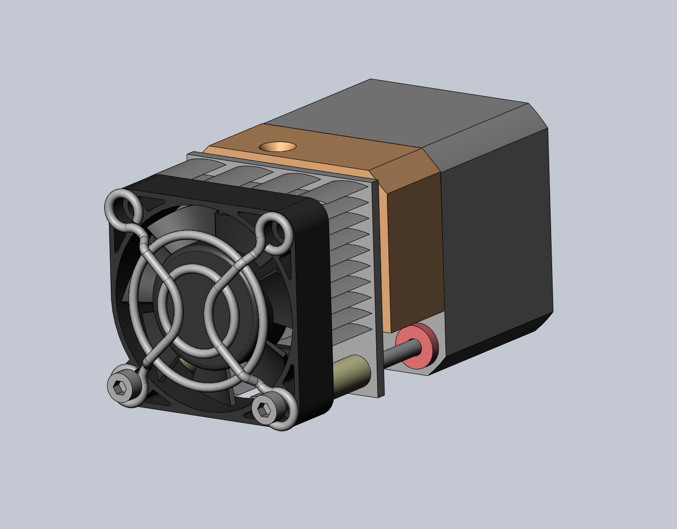
I have a designed upgraded parts which can be swapped into place in under 10 minutes which improve the consistency of the extruder. Here are some sample images of the assembly in place:
The features this design incorporates are:
1) It moves the stepper motor rearward slightly to allow the gripper wheel to engage the flat on the shaft.
2) It adds an auto-tensioning system which includes a bearing and never needs adjustment.
3) It also moves the fan closer to the heatsink so that the airflow must flow through the heatsink instead of past it through a large gap. Also, the motor being spaced off from the heater bar reduces the amount of heat that is transferred directly to the stepper motor.
The materials for these parts are not set in stone yet because only prototypes have been built and tested so far. The plan is to make the bearing mounting components from stainless steel and the filament guide block from either aluminum or delrin for durability. The intention is to find out if there is any interest for a kit like this. The kit would include ALL the parts required for the upgrade (not just a list of components and suggestions where they can be purchased separately). None of the parts will require a functioning 3D printer to install which means you can get a non-functioning or misbehaving printer back up and running easily.
What I need to know is if there is any interest in this upgrade so that I can get a feel for if it is worth making. The prototype has solved my issues and I am happy. I want to allow others to enjoy the full functionality of their investment.


DHeadrick

brain...@comcast.net
DHeadrick
brain...@comcast.net
DHeadrick
DHeadrick
Am I wrong?
DHeadrick
https://groups.google.com/forum/#!searchin/makerbot/John$20watson/makerbot/L_SAu7I_avs/Q0lETfsR2A4J
On Friday, 12 April 2013 16:17:40 UTC-4, John Watson wrote:

Eighty
brain...@comcast.net
Eighty
I'm curious about what makes your design better. I'd like to see a pic of the guts, as I can't tell how yours is any different (aside from the setbacks and missing lever).
DHeadrick
DHeadrick
Eighty
Eighty

Joseph Chiu
Depends on how tightly it was adjusted. Mine looked like that after about 40 hrs (IIRC), when I called MBI for a replacement.
--
You received this message because you are subscribed to the Google Groups "MakerBot Operators" group.
To unsubscribe from this group and stop receiving emails from it, send an email to makerbot+u...@googlegroups.com.
For more options, visit https://groups.google.com/groups/opt_out.
Eighty
DHeadrick
Also, the plunger head is larger than the width of the gripper wheel slot so eventually it will wear and not be able to be adjusted any closer to the filament.
On Friday, 12 April 2013 20:26:16 UTC-4, James Spencer wrote:
I don't see how you can wear that kind of groove into the plunger in 12 hours. That should take more time than that.
DHeadrick
DHeadrick
As promised, here are some images to explain the merits of the design.
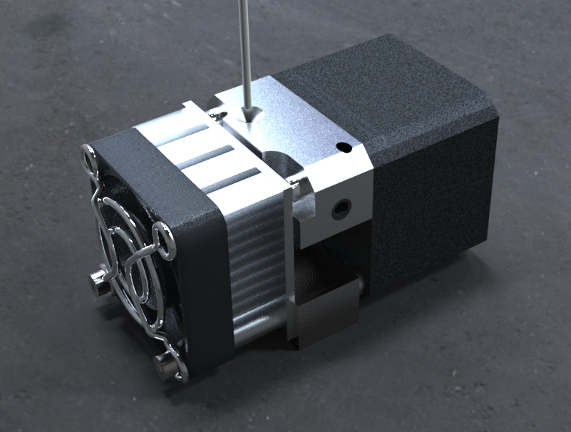
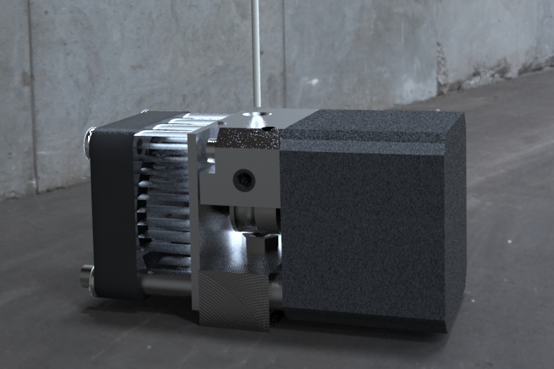
These first two images are just the full assembly and then the extruder without the heatsink and fan attached.

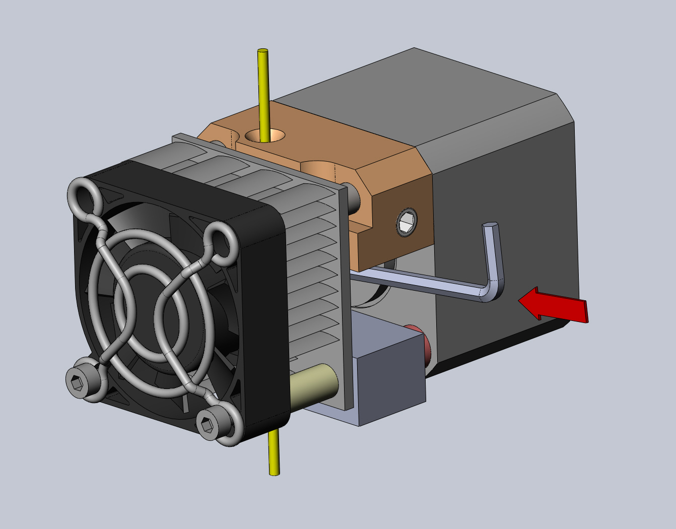
The follwoing image shows a section view to illustrate how the motor is moved rearward to allow the setscrew to land on the flat of the shaft.

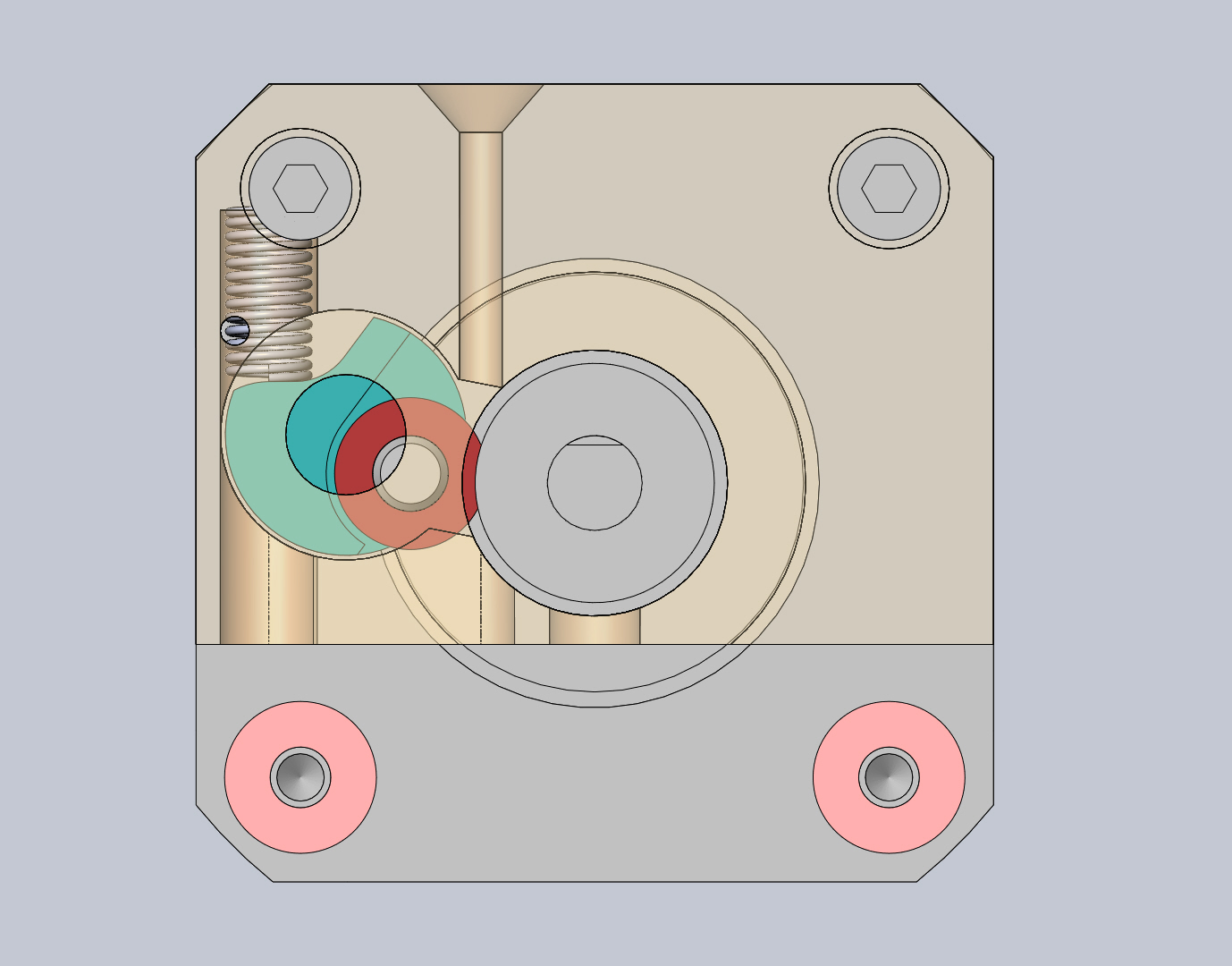
This next image shows a view down the filament feed path showing how the filament is guided the entire way to the gripper wheel. Also shown is how the bearing (red) is sized so that it can fit into the groove in the gripper wheel enabling it to adjust for a large range of filament thickness variation.

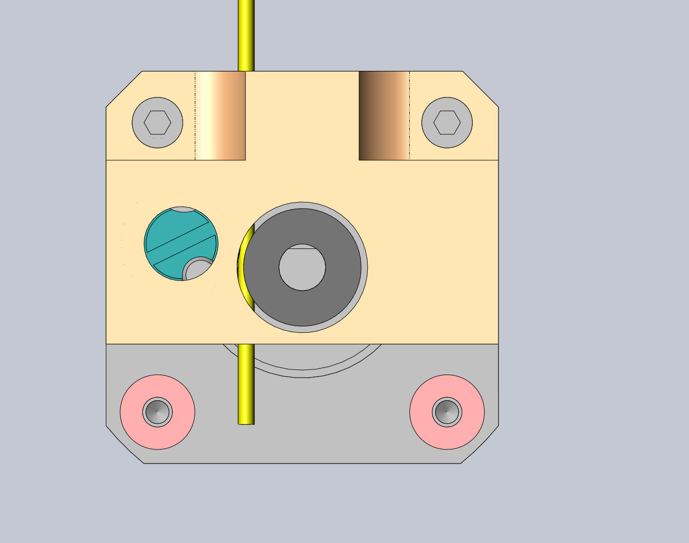
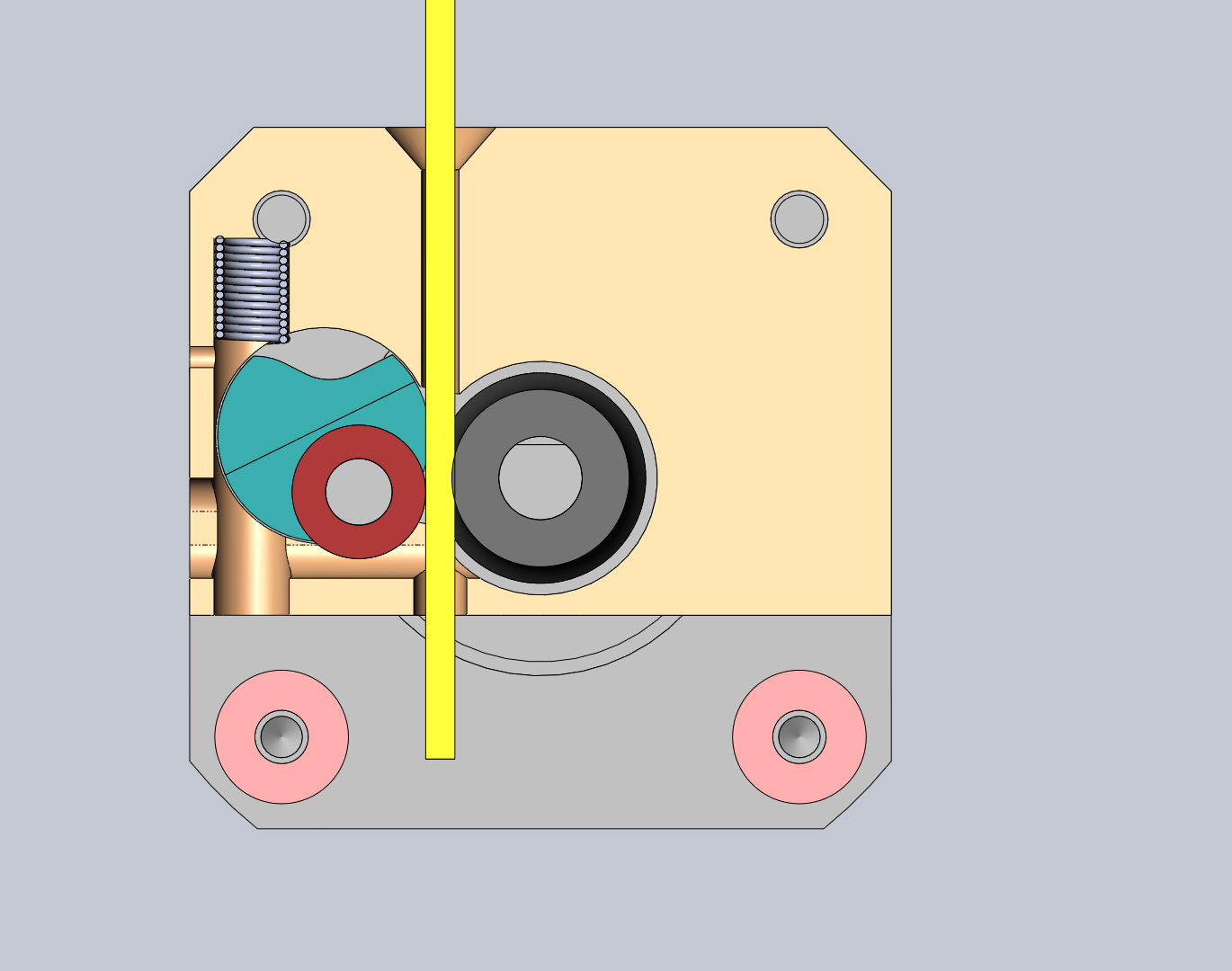
These next two images show the extents of the mechanisms auto-adjustment range. It can adjust down to filament that is as small as 0.5mm in diameter and open up to completely clear the path (which is the same as stock - 2.25mm).

I welcome comments.
DHeadrick

Eighty
1.) Have you logged many hours on this design? I'm wondering how the enclosed nature of this affects the heat creep issue. I've been operating under the assumption that we'd want more open air to dissipate heat above the barrel, but you never know until you try something different.
2.) One concern I have is if/when there's a jam that requires disassembly with the filament still loaded. It doesn't seem like you can access the area below the pinch wheel, to cut off the filament. I've had to do that before, so that I could remove the extruder. So you could end up with a situation that requires a lot of yanking to rip the stuck filament out along with the extruder assembly. Did that make sense?
3.) Have you performed a lot of unload procedures where a blob comes out at the end? As we discussed earlier, I'm still concerned about that blob getting torn off because you can't release the spring pressure.
4.) Looks like you have a much shorter moment arm that other versions, but compensate by compressing the spring to its fullest. I wonder how the result compares - i.e., total compressive force on the pinch wheel.
DHeadrick
1) I have logged only a few hours of printing so far on the design but continue to run it looking for a failure. I haven't experienced any problems but only time will tell. The fan/heatsink combo with the reduced gap as well as the small spacers between the heater block and the stepper motor help prevent heat from conducting into unwanted areas. I have personally found that printing with an extruder temp higher than the default works better (235*C - 240*C).
2) There IS a gap between the guide block and the heater block inlet nut to allow scissors to cut the filament in the case of a major jam. To do this (with most designs - stock included) you have to remove the fan/heatsink to get to this area, but it is possible.
3) In order to test the pull strength of the gripper/tensioner combo, I had to load and unload filament. Sometimes there was a blob on the end but never a huge gob. Do you have some possible steps to produce this so I could try it and get back to you?
4) I have had to try multiple spring rates to produce the desired force. Too much force and the bearing pinches so hard that the stepper can't increment to the next step and just clicks in place. Too weak and there isn't enough pinch force to feed properly. I think I've zeroed in on the ideal force but I need to continuously run the printer to test it out. I think I will start building a block which is the maximum volume of the build space to give it a sufficient test (it will have to be over a weekend).
DHeadrick
Eighty
The only suggestion I have for creating blobs is to heat up the extruder (loaded), and let it sit for a few minutes. Then unload. You'll usually find that the plastic above the barrel slouches down into a bit of a pile.
Glad to hear that you can snip off the filament in place. Sure you have to remove the heat sink/fan, but anything more would be a pita.
From my experiences, prints that go past 8-10 hours usually have heat issues (which I have yet to completely identify). You don't necessarily need a huge model, just take a smaller one and slice it at 100um. That's a good test too, because the filament isn't being expelled as quickly as a 200+um print.

Dan Newman
On 12 Apr 2013 , at 8:19 PM, DHeadrick wrote:
> I have installed OpenSCAD and am still unclear as to how to open an STL
> file to convert it back to something that is usable by CAD software for
> modification... I'll keep reading :)
you will see that the OpenSCAD commands load an STL file and then use
it. (In the case of the heart gears, it intersects it with algorithmetically
generated cube gears.) Anyhow, that .scad file will show you how to
open an STL file in OpenSCAD.
Dan
Dan Newman
that way, the heatsink cooling fan is not even running. That has the best odds
of giving you one of those big blobs. (Happens to me from time to time: I have
to run and I don't want to leave the printer on, even not printing. You get
gunshy that way with your Rep 1 after you've replaced the motherboard once
already.)
Dan
DHeadrick
Dan Newman
On 12 Apr 2013 , at 9:25 PM, DHeadrick wrote:
> OK... got OpenSCAD to import an STL file I made but still see no easy way
> to modify it. I could use boolean operations with geometric shapes to
> modify it within OpenSCAD but no way to export it to anything useful to
> other programs.
convert STL to other formats. If that's your goal -- convert an STL
to other formats -- I myself do not have any good suggestions for you.
(Not too sure why it was suggested to you if that was your goal.)
Dan
Dan Newman
On 12 Apr 2013 , at 8:19 PM, DHeadrick wrote:
> file to convert it back to something that is usable by CAD software for
> modification... I'll keep reading :)
convert STLs to other formats is to use Blender. Blender, which is free,
happens to have a steep learning curve. But there tends to be a problem
even after you convert the STL to another file: it's still just a bunch
of triangles with no underlying nice CAD rational behind them. That is,
the CAD program will still just have a mesh of triangles and not some
nice recognizeable union/intersection/whatever of primitive solids. Even
a simple cylinder will no longer be composed of some circles: it's just
a bunch of triangular facets approximating a cylinder.
So, you may then be able to convert the STL to another format and then
resize, punch holes through, cut sections off of, etc. the result. But
you won't have a suddenly nicer model with which to work in the CAD
program.
Dan

Bottleworks

David Celento
YES. Imperative to reduce heat to drive motor (and diminish internal drive motor heat). In fact, the Rep2x moved it back. Personally, I'm beginning to think the heat sink may be a bigger problem than it is a solution as it blocks air to the filament AND creates a chimney for heat to rise in and around the filament. Cut it in half horizontally? Drill holes in it? I dunno. Testing needed.
Most seem happy with the upgrades by users (and possibly MBI's, if the hole in the bottom is big enough and the shoulder screw seats on the motor). Whpthomas' Rep 2 (in ABS if possible) in particular has proven to work well. To prove your design is better -- and it may very well be, which would be great! -- you'll likely need to print 2-3 hundred hours of varied sized prints, up to a few 24 hour prints using no accelerated AND accelerated speeds. If you convince the experienced users here with results, you've succeeded!
As for STL to editable NURBS -- this is black magic. Very few programs do this. The one that does it best (that I know of) is Geomagic. It takes an (STL) pointcloud and wraps it with NURBS surfaces. At about $30k, bring your wallet! Netfabb might work (have not tried) and maybe Rhinoceros (perhaps aided by plugins).
Eager to learn of other's success stories converting polygons to NURBS.
Good luck w your design project and keep us posted!
David Celento
No doughnut for you! ;-P
Eighty
On a side note, Autocad (and Inventor?) have a shrink-wrap function.
David Celento
For me, peace of mind -- and the elimination of one of many variables preventing proper printing out of the box -- took 5 minutes with a file. Perhaps it's just cheap insurance for those running out of swear words! :-)
Joseph Chiu
I imagine it has something to do with the filament too. Some of my PLA has little bumps, kinda like embedded grains of sand. That probably cuts right into the Delrin. Joseph, did you notice that on the samples I sent? I was surprised when I got your samples, as they were much smoother (and a little translucent).
Dan Newman
On 12 Apr 2013 , at 11:01 PM, Bottleworks wrote:
> You turn your bot off? I never do that. My fears are damage during cold starts.
that assumes that the design is sound. And my MightyBoard did blow on power up.
But I have no way of knowing when the underlying bad event happened which led
to the 5V reg committing suicide by (likely) thermal run away followed by self
explosion. The Bad Deed could have happened when I powered the bot off previously.
I don't know. (As most/all of the logic chips were toasted, it's a safe bet that
at some point 24V spilled onto the 5V rail. That alone -- Vin and Vout shorting
together on that linear regulator -- is enough to take out the regulator in such
a fashion. Typically those regulators can handle a short of either Vin or Vout
to ground as it's part of their built-in short circuit protection. BUT, I don't
know what exactly caused my motherboard to die: the cause may have been something
else entirely such as a failed stepper driver chip.)
At any rate, I turn my bots off when they are not in use. There are components
in them -- the electrolytic caps in the PSUs for example -- which do have rated
lifetimes. OTOH, the PSUs are easier to replace than the motherboards. So, do
what you are most comfortable with.
Dan

Richard
spring combo that keep pressure on the bearing while allowing it to
adjust.
On Apr 12, 9:19 pm, DHeadrick <davidheadric...@gmail.com> wrote:
> As promised, here are some images to explain the merits of the design.
>
> These first two images are just the full assembly and then the extruder
> without the heatsink and fan attached.
>
> The follwoing image shows a section view to illustrate how the motor is
> moved rearward to allow the setscrew to land on the flat of the shaft.
>
> This next image shows a view down the filament feed path showing how the
> filament is guided the entire way to the gripper wheel. Also shown is how
> the bearing (red) is sized so that it can fit into the groove in the
> gripper wheel enabling it to adjust for a large range of filament thickness
> variation.
>
> These next two images show the extents of the mechanisms auto-adjustment
> range. It can adjust down to filament that is as small as 0.5mm in
> diameter and open up to completely clear the path (which is the same as
> stock - 2.25mm).
>
>
> I welcome comments.
Bradley Pearce
added a lever to assist in filament removal?
> You received this message because you are subscribed to a topic in the
> https://groups.google.com/d/topic/makerbot/m2X36BIqEWE/unsubscribe?hl=en-US.
> To unsubscribe from this group and all its topics, send an email to
Eighty
Bradley Pearce
for this concept. Maybe?
http://www.flickr.com/photos/92380311@N04/8636511313/in/photostream

Carl
There are two instances where you will hear the clicking sound... the first (and most obvious) is when the filament is slipping... the second is when the pressure put onto the gear by the delrin plunger forces the gear to touch the other side and stop.
One of my first mods to my machine was to cut away almost everything to the right of the gear - to ensure nothing was able to stop the gear turning - messy, but it worked for hundreds of hours...
The second mod I made was to add a little spring behind the plunger, between the grub screw and nut... this eliminated the need to adjust the tension.
DHeadrick
Carl
Firstly, it depends on what material you are printing with as to the amount of pressure that is required...
The gear needs to be in the correct alignment - the gear teeth on the stepper side are what you want to bite the filament with... not the middle section...
The casing of the standard Rep 2 feeder has warping tendencies when exposed to heat for long durations ie: 10 hr + prints at 235+ deg C. This leads to the parts softening and the sagging when hot - and when cool the parts almost return to their original form. The casing does not allow enough play to accommodate the minute flex on the stepper shaft - even when cool - and definitely not when hot...
If you machine is set up properly PLA can be printed at pretty low temps (around 220 deg C) but that is still hot! :-)
The stepper motor operates at temperature of up to 60 deg C... I'd advice mounting the heatsink to the back of the stepper, the fan to the aluminium cooling block, cutting away any part of the casing that could possibly touch the gear on the side opposite the filament and finding a decent spring to automate the plunger pressure...
This is what worked for me for over 400 hours before I designed my own replacement! :-) Almost everyone with a Rep 2 will eventually have to find their own solution - or use one as suggested above... Pity something that worked did not come installed on my MakerBot Replicator 2...
DHeadrick

David Kessner
DHeadrick
I am running the printer now with these mods and everything is running smoothly so far. I intend to run a 13hr build overnight tonight and should have something to report in the morning.
Thanks again for the useful input.
John Watson
:-)

PhGeis
John Watson
DHeadrick
John Watson
Carl
John Watson
DHeadrick
John Watson
Carl
DHeadrick
I will report back in the morning regarding the outcome of the 13hr print (9 cubic inch block)
DHeadrick
Also, I changed filament from opaque white PLA to clear PLA just before the build and the extruder needed no adjustments for the different filament hardness (I find the clear is harder and more brittle than the white).

DHeadrick
Block created in Solidworks 2012 with fine resolution STL output.
Replicator is using stock firmware 7.3.
Part was exported with Makerware 2.0.2.9
Makerware settings as follows (no custom profile used so all the variables are stock):
Quality High
With raft (no supports)
100% infill
3 shells
0.1 layer height
240*C temperature
80 mm/s extruding speed
150 mm/s travel speed
David Celento
DHeadrick
And a correction to my post above... I'm using bot firmware 7.2 (I'm not from the future).
DHeadrick
I tried printing the "cells bowl" but couldn't get makerware to slice it... so no luck there.
I will post an image of the updated design so that others can see the improvement. The next step is making drawings of the 2 components and get quotes :).
DHeadrick

For those of you interested in math/physics, here are a few noteworthy features of the design. The bearing carriage (blue) rotates about the center of its circular feature. The distance at which the spring acts from this center is constant. The moment distance at which the bearing acts varies depending on the filament thickness. The thinner the filament the smaller the moment distance, but you will also notice that the spring had to extend to move the bearing here thus reducing the force it exerts. Conversely, as the filament gets thicker, the bearing moment arm increases but the spring force also increases to compensate. This design keeps gripper wheel pressure constant throughout the range of movement of the bearing.
You may note that the dozens of lever arm designs on the Thingiverse do not compensate in this manner and can allow pressure to vary with filament thickness and potentially cause problems.
Food for thought.
David Celento
David Celento
DHeadrick
I've never had this issue yet with my printer. I've had where the filament gets stripped and won't unload without a good tug. Also sometimes I have to begin the load function and push the filament then run the unload function and pull to get it to release, but it always comes free. Once I cut the melted filament away, it always loads fine right after this. The exit hole in my block is 0.125" (just over 3mm) so if the blob is larger than this, it won't feed through that (but the heater inlet pipe is smaller).
I keep reading conflicting information. Some people want it all open so they can get scissors in to cut filament. Others want an exit tunnel to keep filament on target as it leaves the gripper wheel on its way to the nozzle. The nozzle inlet is not large so how large a blob can form and where?
Eighty
It's one thing to disassemble the heat sink and fan to snip off the stuck part, but you only want to go through all that trouble when it's truly stuck.
When it's just a mushroomed blob, the easiest thing is to release pinch wheel pressure and let it pass up and out. Provided, of course, that the exitway will let it pass out.
DHeadrick
When this mushroom happens, the unload filament function cannot accomplish this? What prevents the blob from passing?
- is the filament wedged into the nozzle inlet tube?
- is the mushroom too large to force the bearing out of the way?
There is very little room between the gripper wheel and the nut around the heater inlet. If you were able to cut the filament with scissors, what then? Do you then have to remove the extruder assembly and pull out the filament?
Eighty
> - is the filament wedged into the nozzle inlet tube?
> - is the mushroom too large to force the bearing out of the way?
Usually, you unload until it hits a necked-down section. The neck-down happens when the blob is adhering to the tube below, but the top is being extracted (thereby stretching the filament). Eventually, the blob lets go, but you have a stringy part with the blob at the end. At this point in the unload procedure, the pinch wheel can't grab the stringie because its too narrow. You can pull on the free end, but you risk breaking it off along the stringy section leaving the blob inside. So conventionally, we release pressure and tease it out until the blob passes through gently.
> There is very little room between the gripper wheel and the nut around the heater inlet. If you were able to cut the filament with scissors, what then? Do you then have to remove the extruder assembly and pull out the filament?
As I said, snipping is only required when something is jammed and you can't extract it from the top. So at this point, you take off the heat sink and snip it from the front (below the pinch wheel). Then slide the stepper back and use needle nose pliers to pull out the stuck-in blob. The concern is that I'd you can't snip from the front, you have to take apart the top shroud so as to remove the stepper vertically. That's just more work.
Keep in mind that the competing system has both an easy-release lever and a front-facing port for snipping. So giving up either of those options puts your system at a disadvantage. Unless, of course, you've offset that with a huge advantage elsewhere in the functionality.
David Celento
I suspect the blob forms somewhere deeper in the feed nozzle and the diameter is generally not larger than the filament. It appears to me that this element (which happens pretty near 100% of the time on unloads) is a function of stretch on filament at the edge of the melt zone. A small portion of the filament starts to detache slightly from the strand upon retraction. Possible resistance in the tube as it withdraws causes it to neck (meaning, from top down: filament, slight neck, small chunk of filament -- aka "the blob" -- then thin thready wisps) or it simple necks because it's starting to melt a couple mm from the tip. Hard to say.
The central point (where Eighty and I completely agree) is that the pinch wheel needs to facilitate COMPLETE pressure removal on unload (and for every unload) so the bearing does not apply pressure to the neck, causing it to fracture off and jam. Only some kind of lever style mechanism for pressure release seems to offer the ease of use and functionality needed.
As for being open, versus closed, below the drive wheel, I see two arguments. Open is nice "if" it jams (but this may actually "cause" jams). If closed, jams may be eliminated -- but only if nothing unexpected happens! :-)
Your inquiry is applauded!
DHeadrick

A - Stripping (caused by gripper slipping and grinding away the filament)
B - Teeth marks made by the gripper as it meets resistance and tries to force more material into a plugged nozzle
C - Stringy Neck due to stretching of the hot filament upon unloading
D - "The Blob"
I have thought of a way to allow access to the filament if it needs to be cut but haven't quite devised a way to release pressure entirely short of removing the spring (which means having to dial in the pressure again - which I don't want to force on the user because it takes time which could be spent happily printing).
My idea for accessing the filament would also allow you to brush off the gripper wheel if it is experiencing a build up of filament bits which are causing slipping. I have read where people have had to increase the extrusion stepper speed just to make up for lost traction due to the teeth getting filled with filament buildup. This filament access would allow you to look and see if this is the case.
Now I just need to allow the user to release pressure.

TobyCWoods
David Celento
I suspect that "B" may be normal and probably is desired. Positive grip with no slip.
If one is speeding up the feed due to particle buildup in the wheel, the problem which really should becaddressed is that the wheel has not enough pressure applied to the filament (creating small shavings) and it needs to be cleaned.
DHeadrick
I am going to print one out and install it to ensure it functions as well as the current prototype.
Thoughts?
On Saturday, 20 April 2013 23:43:49 UTC-4, David Celento wrote:
If one is speeding up the feed due to particle buildup in the wheel, the problem which really should be addressed is that the wheel has not enough pressure applied to the filament (creating small shavings) and it needs to be cleaned.
David Celento
Giver 'er a shot!
Eighty
If you're pausing mid-print to swap colors, you can't fit a tool in there. The bot will have homed, and that side will be up against the endstop.
So with this setup, the only way to do it is to jog the X axis over a bit. Not the end of the world, but I'd prefer not to jog during a pause. I don't want another thing to worry about (losing stepper registration). And I don't even know if the MBI firmware will let you jog during a pause.
DHeadrick
Eighty

Kerry Chin
I just printed myself a new Makerbot extruder upgrade and I still can get the thing to run for more than 60 minutes before this happens. I even installed a new heater block assembly at the cool cost of $120.
I used to run 15+ hrs prints no problem, but even now, after new heater/nozzle and extruder upgrade, this thing jams. It's spinning out and getting stuck. Ahhh! So frustrating.
Is it normal to have the stepper motor getting so HOT? I don't remember it so hot before...
DHeadrick
DHeadrick
DHeadrick
This design allows all the features of the existing solutions and:
1 - Allows positive engagement of the gripper on the motor flat.
2 - Adjustable spring tension with release capability.
3 - Allow better heat dissipation during long prints by having a large port for heat to convect away.
4 - Allow visual access to the gripper wheel and even the heater inlet port.
5 - Allow scissor access in the case of a filament jam
6 - No additional cost (this is my very attainable goal)
7 - Aluminum guide block for heat resistance
8 - All parts required included in the kit (including the spring adjustment hex key)
Below are some photos of the final prototype which will be send out for manufacturing quotes.
DHeadrick


DHeadrick
It was the first time I had experienced what people were describing in the previous comments. I was impressed that the jam could be so easily fixed.
DHeadrick
Wingcommander whpthomas
Thanks for your applause. If everyone stuck to what was available we would all be driving cars from the 1950s because they do the job.
1 - Allows positive engagement of the gripper on the motor flat.
2 - Adjustable spring tension with release capability.
3 - Allow better heat dissipation during long prints by having a large port for heat to convect away.
4 - Allow visual access to the gripper wheel and even the heater inlet port.
5 - Allow scissor access in the case of a filament jam
6 - No additional cost (this is my very attainable goal)
7 - Aluminum guide block for heat resistance
8 - All parts required included in the kit (including the spring adjustment hex key)
DHeadrick
On Tuesday, 23 April 2013 20:52:46 UTC-4, Wingcommander whpthomas wrote:
So a quick critique of you list1 - Allows positive engagement of the gripper on the motor flat.Not sure exactly what you mean by this one, but if you think pulling power is an issue, the Minimal au Mk8 will lift a tangled spool without slipping - it grips about as strong as the stepper can push or pull.
What I mean is if a motor shaft has a flat and the gripper has a set screw, they are only there to serve each other. Putting those features there and then not properly utilizing them is sad. I have read numerous posts where people have had their gripper slip on the hardened motor shaft. I have corrected this oversight so it never becomes an issue again. Just because yours can pull a car out of the mud doesn't mean everyone's can or will or may not have that problem in the future.
2 - Adjustable spring tension with release capability.
If it has the right spring tension from the start then for PLA adjustment is not necessary - but for ABS and Nylon this could be an important feature to have [TICK]. Thanks :)
3 - Allow better heat dissipation during long prints by having a large port for heat to convect away.Well speaking from experience, the aluminium works as a large heat soak, air flows in from the left side through the cowling and inside the top covering and leaves through the gaps in the spring. The stepper is also cooled by the cooling block - consequently the stepper runs cool to touch even after 22hours of non-stop printing. Not sure this is a real problem in practice.
My guide block will also be aluminum and there is sufficient clearance that the potential for heat to be contained and build up is mitigated. I'm not sure there is a real problem here either, but I don't print with ABS or Nylon yet.
4 - Allow visual access to the gripper wheel and even the heater inlet port.
No argument here [TICK]. Thanks again :)
5 - Allow scissor access in the case of a filament jam
No argument here either [TICK]. Thanks again :)
However, you can prevent blobs on the end of the filament forming by doing a quick load before unloading so in practice this is not really a problem I have encountered. The upside of the Mk8 is that manual filament changes are really quick. To do this, I tend to grip the under side edge of the extruder with my fingers, depress the lever with my thumb, push the filament down to clear any blobs, and then pull it out. It never jams, and filament changes are really quick - you to the same thing to reload - insert filament, release tension with thumb, then push it all the way down until a small amount leaves the tip and resume print. If you have two feeder tubes and the second real is already prepped, you can do a colour change in a mater of seconds. The minimal Mk8 has a real benefit here.
My design also has a quick release of the spring tension so that you can pull the filament out and insert a new one in a matter of seconds. The only difference is you have to use the 2mm hex key that came with your Makerbot to do it. You insert it in the hole as shown in the images in the previous post. Same as your lever except you push on a hex key (or screwdriver or rod if you desire).
6 - No additional cost (this is my very attainable goal)I place a value on my time of about $100 per hour - your calculation might be different - but contributing to this community is fun, so I do it pro-bono ;) - but I still value the time I contribute non-the-less.
I also value my time as most do. I was disappointed at all the time I had to spend dicking around tuning the Makerbot just to get decent prints. If there was a replacement that would fix most of the known issues in one easy kit, I would have bought it. From what I've read, people buy/print a lever arm. Then they source the bearing and spring (if they had to print the arm) and assemble it. Then they may have to use a file to extend the motor shaft flat (if they have that issue). These are all factors that are a pain in the ass and have all been addressed by this design! And I believe it can be done at the same cost as the currently available aluminum kits (~$99) yet solve more issues at the same time.
7 - Aluminum guide block for heat resistanceAluminium is a relatively efficient thermal conductor?
I should clarify. It will be made of aluminum so that it won't warp if the extruder does overheat. I've read about people using the PLA upgrades and having them warp under heat (some people are on their 4th replacement).
8 - All parts required included in the kit (including the spring adjustment hex key)I thought no cost was a feature i.e. item 6 above?
I will throw in the hex key to adjust the spring tension (because none of the keys that came with the Makerbot will fit the set screw). The hex key costs 17 cents to the parts... I think I can handle that to ease the buyers frustration. My goal is to offer this kit for the same price as the competing aluminum upgrade kit.
---- ~ ----So from this list I would focus on tension adjustment for different filaments that might need more fine tuning like ABS, Nylon, Wood and PVA (Done - spring force adjustment is possible and easy) - but these claims would need to be supported with some evidence of the benefits of you design compared to the alternatives (agreed). The ability to access and visually inspect the top of the hot end is a real advantage. While for me this is not really an issue in practice, every now and then it would be really handy - I have on a very few occasions had to remove the extruder due to filament that was molten getting carelessly squished by the pinch arm and not being able to pull it out (I agree it is a unexpected bonus of the part layout of this design).The downside of your approach is that mid-print filament changes may be potentially slower (Not any slower than the lever arm style - I will post a video to demonstrate in the near future).
So what would really trump the Minimal Mk8 is if you could add a quick release cam to unlock your tensioner - that I would applaud, very loudly - food for thought =)
Thanks for your insight. This discussion thread has really helped direct the design of this upgrade into something I think will make the Makerbot much easier to use.
Wingcommander whpthomas
What I mean is if a motor shaft has a flat and the gripper has a set screw, they are only there to serve each other. Putting those features there and then not properly utilizing them is sad. I have read numerous posts where people have had their gripper slip on the hardened motor shaft. I have corrected this oversight so it never becomes an issue again. Just because yours can pull a car out of the mud doesn't mean everyone's can or will or may not have that problem in the future.
DHeadrick
On Wednesday, 24 April 2013 00:22:02 UTC-4, Wingcommander whpthomas wrote:
Just for future reference I think most call it a hobbed drive gear (hobbing is the process that gives it the little indentations that make it grip the filament).
Ah... I was aware hobbing was used to produce involute gear teeth but didn't realize it was used for this. I was under the assumption that it was a straight knurl in a groove.
Just finished a 15.5 hr print of a solid PLA block (3.375" x 3.375" x 1.5") at 100% fill unattended overnight with no defects. Between this prototype and the previous one that was installed (same design but different spring layout), the design has logged around 70hrs of printing. Everything was cool to the touch while it was still printing at the 15hr mark (I touched the motor, cooling block, heatsink).
TobyCWoods
DHeadrick
DHeadrick
I am really excited to get this out there so more people can immediately start to use their printers without having to perform multiple tweaks just to get up and running. I know how frustrating it can be when you first receive the printer and start printing and something goes wrong. Your first thought is that you set something up wrong or entered wrong parameters.
I will be sure to post as soon as I have more details.
On Sunday, 28 April 2013 09:32:11 UTC-4, Steve Bartholomew wrote:
I'd buy one today.
On Friday, April 12, 2013 3:41:55 PM UTC-4, DHeadrick wrote:I have read many posts about issues people have experienced with the Makerbot 2 shortly after receiving one. I was only reading for interest until a few of these issues began to rear their head. It is disappointing to have spend $2500 on a 3D printer and not be able to use it after as little as a week of printing. My problems showed up within 12 hours of elapsed printing time! This is not acceptable. Unfortunately, my printer was no longer capable of printing out good enough parts to try any of the many fixes available on the web.
Luckily, I had access to other methods of manufacturing and have been able to design a few replacement parts which have completely resolved a few issues. Here are the issues I found as I took my extruder head apart:
1) The filament tension mechanism is an appalling design and it is obvious that it will never allow for consistent printing of quality parts.
2) The gripper wheel that advances the filament does not engage the flat on the stepper motor shaft.
3) The excess heat from the melter is allowed to travel away through the heat sink (where it should) but also the stepper motor housing (where it should not).
I have a designed upgraded parts which can be swapped into place in under 10 minutes which improve the consistency of the extruder. Here are some sample images of the assembly in place:
The features this design incorporates are:
1) It moves the stepper motor rearward slightly to allow the gripper wheel to engage the flat on the shaft.
2) It adds an auto-tensioning system which includes a bearing and never needs adjustment.
3) It also moves the fan closer to the heatsink so that the airflow must flow through the heatsink instead of past it through a large gap. Also, the motor being spaced off from the heater bar reduces the amount of heat that is transferred directly to the stepper motor.
The materials for these parts are not set in stone yet because only prototypes have been built and tested so far. The plan is to make the bearing mounting components from stainless steel and the filament guide block from either aluminum or delrin for durability. The intention is to find out if there is any interest for a kit like this. The kit would include ALL the parts required for the upgrade (not just a list of components and suggestions where they can be purchased separately). None of the parts will require a functioning 3D printer to install which means you can get a non-functioning or misbehaving printer back up and running easily.
What I need to know is if there is any interest in this upgrade so that I can get a feel for if it is worth making. The prototype has solved my issues and I am happy. I want to allow others to enjoy the full functionality of their investment.
David Celento
John Watson
--
DHeadrick
How long typically before heat soak rears its ugly head?
I would love to print that cell bowl but have had no luck slicing it. I've tried Makerware and Repetier and both have issues (Repetier uses both Skeinforge and Slic3r). I don't have ReplicatorG configured to the geometry of my bot yet. Can you give me any tips?