0.3mm & 0.2mm Nozzles on a Replicator - anyone tried it?

1,073 views
Skip to first unread message

Steve Johnstone

unread,
Feb 6, 2014, 3:47:05 AM2/6/14
to make...@googlegroups.com
Hi all,

Currently the thinnest single wall I can print with a 0.4mm nozzle, in ABS, is 0.48mm regardless of layer height (Upgraded Replicator 2X).

This is way beyond my original expectations; however I would like to know how far I can push it.

Ideally I was hoping someone could recommend a 0.3mm / 0.2mm nozzle supplier. Obviously I have had a look on eBay, but would prefer a recommendation - some of the Chinese nozzles don’t look the best of quality.


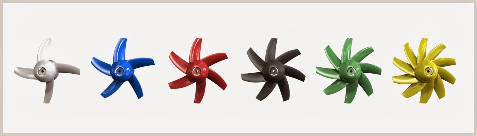
 I’m working on the ducting for a Micro EDF Hawker Hunter RC Jet and need to get the weight of the printed parts as low as possible.  

To give you some idea the pictures below are of the first printed prototype ducting and will be used to test the thrust & drivetrain etc.


CAD GAs


The printed parts making up the duct.


With a needle to give an idea of scale.


Using the head of a sewing pin for scale reference.


Federico Boldori

unread,
Feb 6, 2014, 5:18:20 AM2/6/14
to make...@googlegroups.com
I have not an answer for your questions, but beautiful project and design!

Jetguy

unread,
Feb 6, 2014, 8:05:09 AM2/6/14
to make...@googlegroups.com
A search for "smaller nozzle" would have handed you several in depth threads on the subject.

That said, QU-BD would be where I got nozzles and NOT Fleebay.

My general comments:
ABS is not an ideal plastic for smaller nozzles and PLA is going to be the print material of choice
You had better have the ultimate gripping filament drive.
You had better have the worlds flattest glass bed.

Keep in mind, smaller nozzle requires lower layer height between 1/2 and 3/4 layer based on nozzle width.
So a.25 nozzle requires a layer height of about 0.1mm to say 1.7mm and an extremely flat bed surface trammed to perfection.

If the rod sag is as bad as some folks claim, then you'll never be able to pull this off. https://groups.google.com/d/msg/makerbot/W-zmnBXZMBw/H3q9V0YEy_UJ

Steve Johnstone

unread,
Feb 6, 2014, 9:07:49 AM2/6/14
to make...@googlegroups.com
Fantastic Jetguy, thankyou.

I did do a search for 0.3mm extruder nozzles.... never thought of trying "smaller nozzle".

I know I'm asking a lot of the printer, but I'm one of those guys that if I don't try it's going to bug the hell out of me!

  • I will experiment with PLA, HIPs etc.
  • The extruder drives are working fantastically well (1in3)... no issues there.
  • I'm on cheap glass so that may cause problems.
  • I'm have been printing regularly at 0.1mm with the 0.4mm nozzle for this project, so I might just get away with it. I wouldn't normally bother going below 0.2mm layer height but I need the internals surfaces as smooth as possible.
  • Yes my rods do sag... not much I can do about that. Perhaps custom rafts / beds???
 
I will have a read up on you links and take it from there.

Thanks again for your time.

Scottbee

unread,
Feb 6, 2014, 9:46:31 AM2/6/14
to make...@googlegroups.com
If your rods are really "sagging" (and not just bent) and you're not running a hood (like the 2X) then the "sag" can be "mostly" eliminated.  The "trick" is to counterbalance the extruder/carriage/rod assembly so that it represents an effective "weight" of 0 along the Z axis.

There are elegant ways to do this, but in practice a long elastic cord anchored to the carriage and a distant point directly overhead (like the ceiling) will do the trick nicely.  You want the elastic cord to have a low spring rate (K) and set the static tension so that it equals the weight of the extruder carriage assembly, X-axis rods, X-ends, stepper, and etc..  You are essentially off-loading the weight off of the Y-axis rods.  It's not a theoretically perfect solution since you will now be introducing an upward force on the X-axis rods.  In practice you can probably reduce the tension to about 75% and find a compromise between upward deflection on the X rods and downward deflection on the Y rods.

The elastic cord should have little effect on the effective mass of the carriage, so I wouldn't expect acceleration problems.

This is not a theoretically "perfect" solution, but I'm willing to bet that you would be able to eliminate 75+% planar error associated with rod deflection.

(If this has already been addressed or discussed in a different thread I apologize....  I haven't read the entire forum (yet))

Scottbee

unread,
Feb 6, 2014, 10:14:26 AM2/6/14
to make...@googlegroups.com
To take the ^^^ above post one step further.  If you wanted to be Uber-anal about it, there is a three-spring (three cord) implementation that should/could give you near perfect (theoretical) results.  One cord for the extruder carriage, one cord for the left end of the X gantry (X-ends) and one cord for the right end.  Tweaked properly you should be able to unload all of the rods.....

Ryan Carlyle

unread,
Feb 6, 2014, 11:32:22 AM2/6/14
to make...@googlegroups.com
This has crossed my mind a few times. Although I was thinking a rail/pulley system inside the hood -- basically set up a secondary rod ~1 ft above the Z rods, and run a tension member from the upper rod to the X ends.

Scottbee

unread,
Feb 6, 2014, 11:36:59 AM2/6/14
to make...@googlegroups.com
Of course, this could also be rectified by a "sag aware" slicer or post-processor....    ;)


We used to call this "PATMDOM" (Pat. M. Dom)... Programming Around The Mechanical Deficiencies Of the Machine......

Joseph Chiu

unread,
Feb 6, 2014, 1:21:05 PM2/6/14
to make...@googlegroups.com
I'm just imagining printing on the Vomit Comet... IIRC, there is a "We are diving" indicator to indicate when a powered dive is in progress -- perhaps that can be wired to the P-stop.  :)


--
You received this message because you are subscribed to the Google Groups "MakerBot Operators" group.
To unsubscribe from this group and stop receiving emails from it, send an email to makerbot+u...@googlegroups.com.
For more options, visit https://groups.google.com/groups/opt_out.

Steve Johnstone

unread,
Feb 7, 2014, 4:10:05 AM2/7/14
to make...@googlegroups.com
Great info Scottbee,

I never thought of overcoming the sag with elastic. At the moment I'm printing small items (40mm Max Diameter) in the centre of the plate. If I have any problems in the centre with the smaller nozzles, my next option is to print in the rear right corner. After that I will reavaluate and decide if it is something worth pursuing.

I have ordered the 0.25mm, 0.35mm and 0.5mm nozzles from QU-BD and they are on their way.

Just for the hell of it, I tried printing an actual rotor last night. I basically threw it together and didn't spent any time designing custom supports etc. as I just wanted to see what would come out the otherside. I was amazed at what I got as it's almost usable. The rotors only cost a couple of £ so it's not a price issue. The big win is being able to design and print custom rotors to suit the brushless motor etc.... no more having to modify existing rotors. I design in SolidWorks and set everything up to be parametric. Adding or removing a blade, changing the cord profile etc. takes seconds if everything is setup correctly in SolidWorks.

I set up these configurations and they took no more than 5 minutes..... exciting stuff :)

Thanks again for you input.

Steve Johnstone

unread,
Feb 7, 2014, 4:15:26 AM2/7/14
to make...@googlegroups.com

BruceA

unread,
Feb 7, 2014, 8:48:09 PM2/7/14
to make...@googlegroups.com
Steve.

 I to build models and understand that weight is an issue and the need for smooth airflow surfaces. just a thought, Tamiya make a surface finishing paint, sort of like a thin spray putty that is used in the auto body works business. If you thin this a bit and pour it into your tube rolling and tilting the tube as you go, then let the excess run out the other end this will coat the airflow surfaces and make them smooth. I used this on the Mountain bike to finish the outside of the frame, you saw and commented on this in print of the week. Any way as I said just a thought that might just work if it does not give you too much of a weight penalty.

Steve Johnstone

unread,
Feb 8, 2014, 8:06:35 AM2/8/14
to make...@googlegroups.com
Thanks for the link Bruce, I will give it a go.

Jimc

unread,
Feb 8, 2014, 4:07:49 PM2/8/14
to make...@googlegroups.com
steve, i have printed with a .25 so here is my 2 cents. my m2 is standard with a .35. you should have no problem with that one. i also have a .25 and have printed in abs with it...again, m2 and not a MB. the .25 shouldnt be too big a deal for you either as long as printing with your .4 is like old hat and everything is dialed in. the .25 will be the same deal. you will just need to tweak the settings and it will take trial and error until you get it nailed. as jetguy said though. you need a flat bed and your nozzle needs to stay consistent gap. if your extruder is sagging in the middle then your just fightin the machine which can just get frustrating. if you get it going good though the prints you get from a .25 nozzle will blow your mind. the detail is amazing. if you do end up using abs you had better be sure its really good stuff. none of that cheap stuff.

Steve Johnstone

unread,
Feb 9, 2014, 2:26:58 AM2/9/14
to make...@googlegroups.com
Thanks for the advice Jim.

I will start with the .35. If I can get this to work and shave .05 off the wall thickness it would be a huge win. I spent some time yesterday testing the ducting in the "as printed state" and the sanded the internals through the grades before acetone dip. I will test again before any more finishing. I really want to stick with ABS as it is so much easier to work with, from a finishing perspective, then PLA.

I don't bother with cheap ABS... I learnt that lesson a along time ago :).

It good to know that it's possible to print with these finer nozzles and look forward to the challange.

Steve Johnstone

unread,
Feb 23, 2014, 8:34:04 AM2/23/14
to make...@googlegroups.com
Just a quick update on this.

I have yet to try the nozzles as I have managed to get my wall thickness down to .35mm with a .4mm nozzle.

I did try HIPS as an alternative to ABS in the hope of reducing distortion but even though there was some improvement it wasn't as strong as the ABS when printed as a single wall.

Yesterday I used HIPS as a support for a 28mm rotor. The support wasn't generated during slicing but designed in cad specifically for the rotor.
After some tweaking I printed 3 rotors, one after the other without any issues. I dissolved the HIPS last night and was left with great prints first thing this morning :).

They each took about 1 hour to print and with a little bit of wet and dry sanding look this ( The white one is the printed version of the black injected molded one)


CAD model of the HIPS support


GA of the rotor and HIPS support

Jetguy

unread,
Feb 23, 2014, 10:16:45 AM2/23/14
to make...@googlegroups.com
Now do that with Protopasta's CF reinforced plastic and then you might have a rotor that can do more than sit in a mockup.
Knowing how fast that ductd fan rotor is supposed to spin, in no way would I even attempt to use a printed one regardless of how great it looked.
 
For a propeller of any kind to be effective, it much be stiff and maintain pitch on top of retaining the tensile strength to not come apart from centrigual force at high speed.
Even say printing in Taulman nylon, the problem is the required rigidity is lost although the tensile strength is there.
In fact, the fiber reinforced injection molded ones are on the verge of barely being strong enough.
 
Sorry, not trying to knock the print, just put a little reality in expectations. Someone else might see that, print one, and spin it at 40K+ rpm then be picking plastic blades out of their forehead or eyes.

Steve Johnstone

unread,
Feb 23, 2014, 11:58:24 AM2/23/14
to make...@googlegroups.com

Frankly Jetguy I think your comments a quite rude. You’re obviously an educated guy so you should be able to phrase what you say in these threads in a more constructive way.

For the record I’m fully aware of all the points you have razed but unfortunately you are ill informed with most of your facts. I’m not going to argue them because frankly it’s just a waste of my time.

Steve

AL M

unread,
Feb 23, 2014, 12:37:08 PM2/23/14
to make...@googlegroups.com
Steve I ordered nozzles from this place Quintessential Universal Building Device - 3D Printers and  Accessories Store] on the 10th and havent even got an email or tracking # they had what looked like quality nozzles 2.5,3.5,4.0 and 5 i bought some from china and they were a joke. Blade looks better than your thumb outch

Ryan Carlyle

unread,
Feb 23, 2014, 12:42:31 PM2/23/14
to make...@googlegroups.com
On Sunday, February 23, 2014 7:34:04 AM UTC-6, Steve Johnstone wrote:
Just a quick update on this.

Looks really good, Steve. I'm about to do my first HIPS-supported print right now. Nothing fancy, just need some cut-out geometry in a cylinder that can't be bridged, for a display piece. 

HIPS is never going to be quite as strong as ABS, because HIPS is just "BS" (butadiene styrene). It's missing the acrylonitrile that gives ABS a lot of its strength. 

Scottbee

unread,
Feb 23, 2014, 1:12:50 PM2/23/14
to make...@googlegroups.com

Nice work...

But there is a "trick" that you may not know of that may save yo a lot of time.  

If you're slicing in MakerWare the right extruder is dominate and will "cut into" any model that is being done with the left extruder.  Soooo....  if you put your rotor on the right extruder and a solid block on the left extruder (the block being larger than the rotor and placed on the build platform to "encapsulate" the rotor) the printer will print the rotor encapsulated in the left extruder material.  When it is done you can dissolve away the block with Limonene.

That can make it easier to create a full HIPS support since you don't have to actually create a detailed support.  Makerware will essentially do the Boolean subtraction for you.

Just $.02

Steve Johnstone

unread,
Feb 23, 2014, 2:01:25 PM2/23/14
to make...@googlegroups.com
I received mine about 1week after ordering, no problems what's so ever - I'm in the uk. I did have an email saying that they were rebranding so maybe your order has got caught up in that. I would drop them a email.

Do let us know how you get on with the smaller nozzles.

Steve Johnstone

unread,
Feb 23, 2014, 2:05:26 PM2/23/14
to make...@googlegroups.com
Thanks for the info Ryan.

Would that explain why it feels brittle and is a lot nicer to sand?

Steve Johnstone

unread,
Feb 23, 2014, 2:16:25 PM2/23/14
to make...@googlegroups.com
Nice tip.

I have't used Makerware for a long while - using Simplify 3D exclusively now. I can see it would be a great way to add HIPS incasement to an STL file you have downloaded.... Never thought of that.

I'll give it a go even if it's just for comparison.

Ryan Carlyle

unread,
Feb 23, 2014, 2:18:56 PM2/23/14
to make...@googlegroups.com
It depends wildly on the ratios of acrylonitrile, butadiene, and styrene monomers used to make the plastic. One way to look at it is that styrene is the "base" plastic polymer, acrylonitrile adds hardness/strength through cross-linking, and butadiene adds toughness/flexibility by including elastomeric chains in the mix. It's a more complicated than that because of the complex nature of the polymer cross-linking, but you get the idea. 

I suspect that if 3d printing grade HIPS is brittle and easier to sand, that's because it has more hard plastic (styrene) and less rubber (butadiene) compared to ABS. But filament manufacturers don't share their formulas so I'm speculating. And I'm a chemical engineer, not a chemist, so don't consider me an expert by any stretch.

Scottbee

unread,
Feb 23, 2014, 2:25:58 PM2/23/14
to make...@googlegroups.com
I have S3D also, but I haven't tried the "trick".  I have no idea how S3D handles it when you have left and right extruder models trying to occupy the same physical space.  It must do something....     ?
Reply all
Reply to author
Forward
0 new messages