Print quality comparison - Makerware 2.0 versus ReplicatorG Sailfish 040R11 - printing on a Relicator2 with Sailfish firmware r00942

Enginwiz


Mike Gervasi

David Celento

Joseph Chiu
Superb comparison! Many thanks for sharing this.In MW, were the only custom profile settings that you modified the ones you listed, or were there more? If so, care to share the entire MW custom profile?
--
You received this message because you are subscribed to the Google Groups "MakerBot Operators" group.
To unsubscribe from this group and stop receiving emails from it, send an email to makerbot+u...@googlegroups.com.
For more options, visit https://groups.google.com/groups/opt_out.


Dan Newman
On 17 Mar 2013 , at 7:54 AM, Joseph Chiu wrote:
> Thanks for the comparison and those pictures, Enginwiz!
>
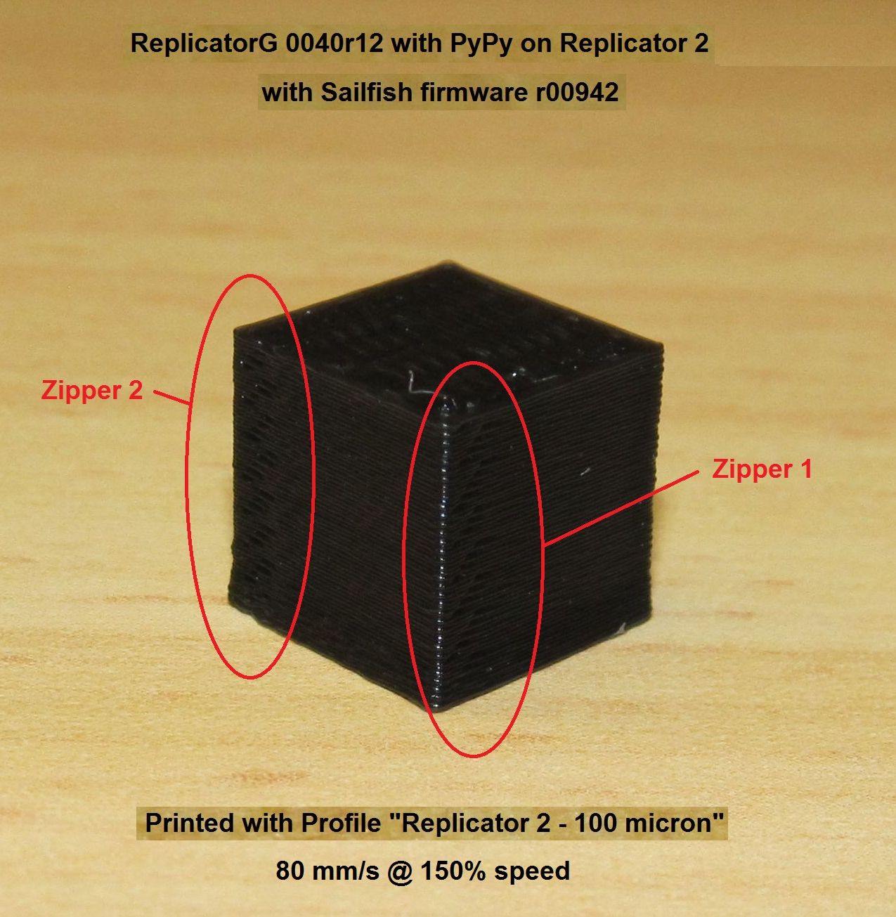
> Those zippers on the SkeinForge cube comes from jitter moving the start/end
> position of the loops. Looking at the picutre of the calibration cube by
> MakerWare, I don't see loop start/end's at all. Could you send the Gcode
> for the MW calibration cube output? I have a hard time believing the loop
> ends could merge together that nicely. (I would love to be proven wrong.)
> Could it be that the loop start/ends are somewhere else? Perhaps right at
> the corners?
>
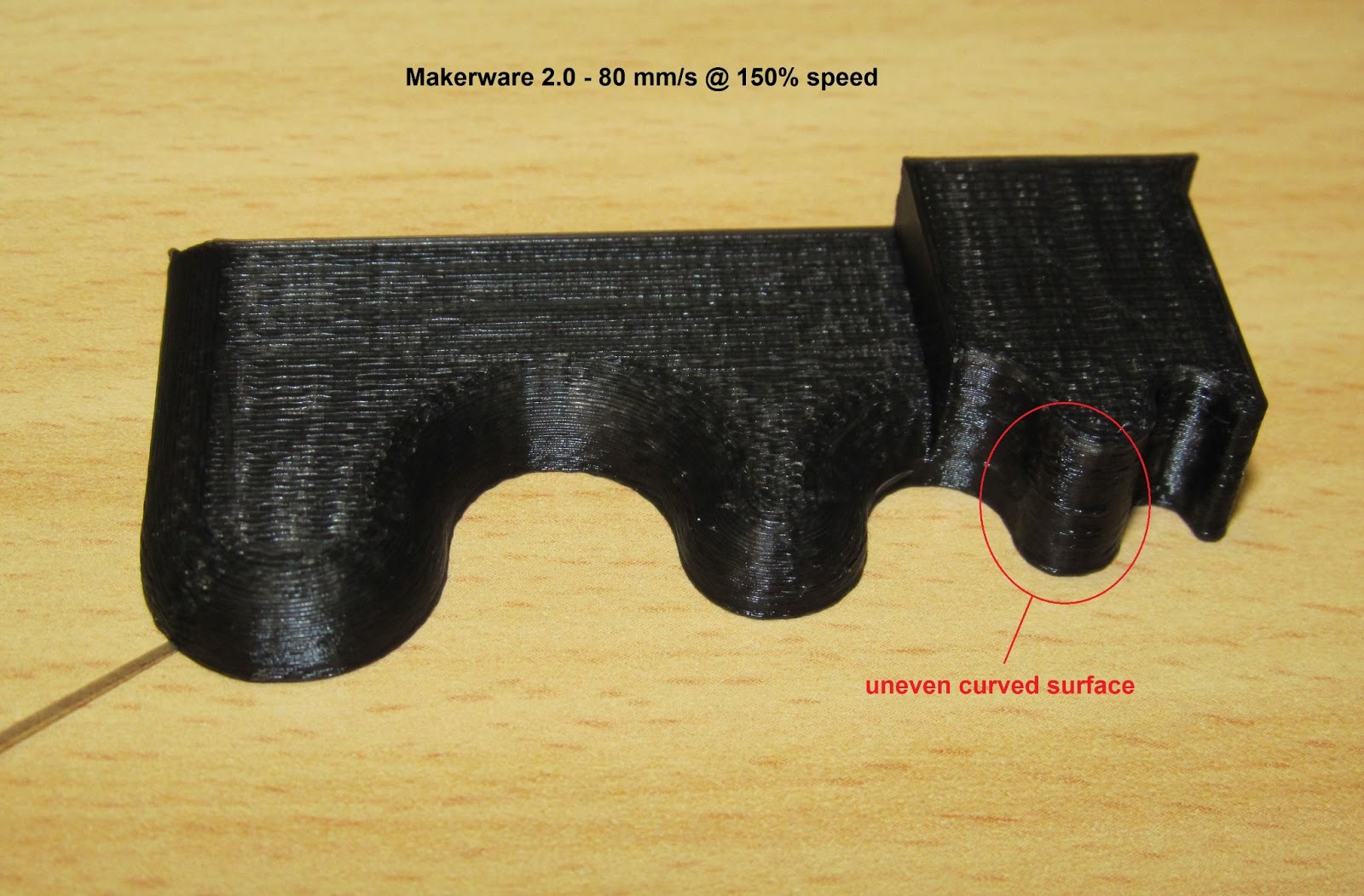
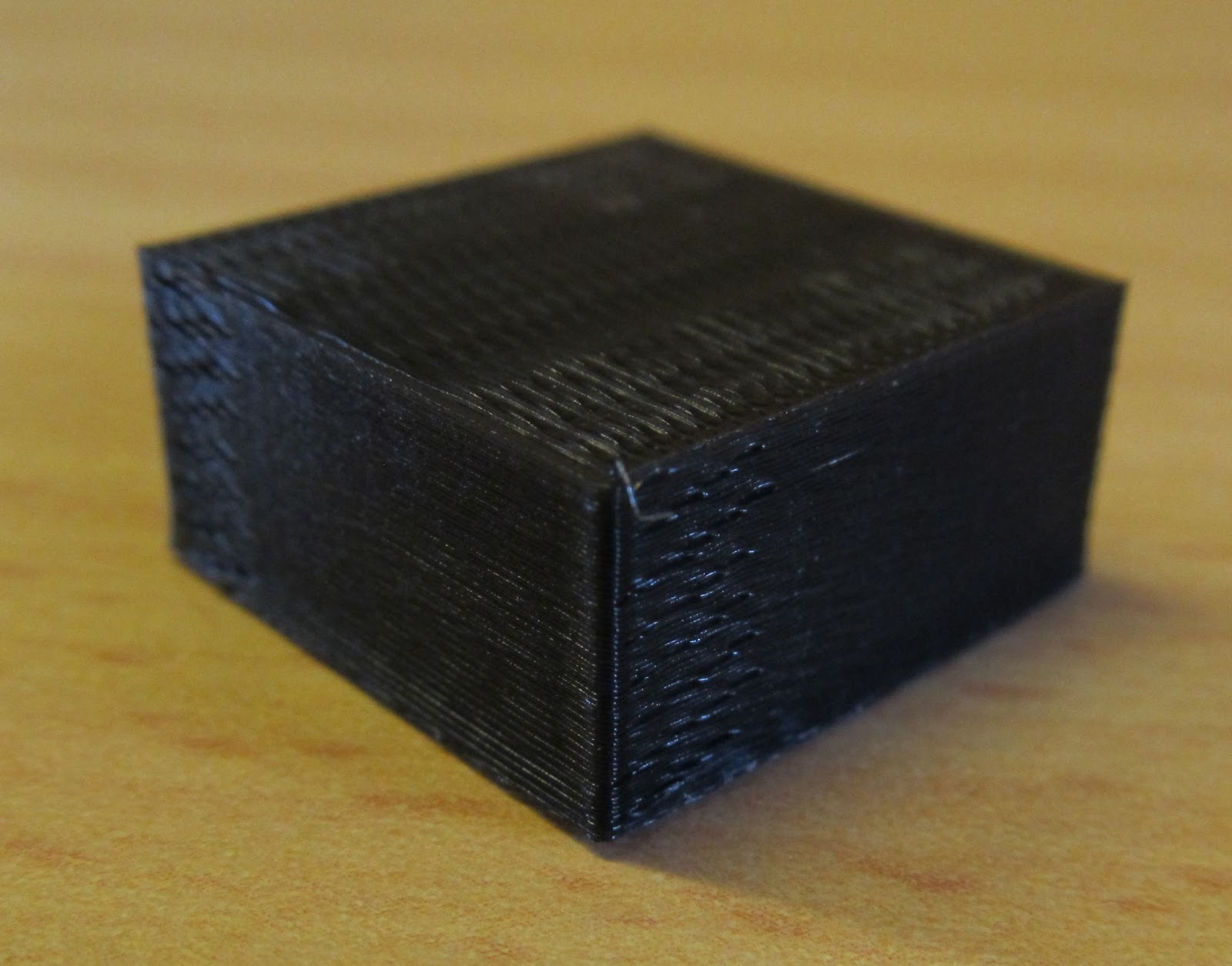
> In your last picture, you can actually see loop start/end's on the MW
> prints -- they are not jittered, though:
>
> I think this suggests that at higher speeds, SF jitter is lowering print
> quality by introducing layer-to-layer phase variations on the ringing
> ripple patterns. Put differently, if you turn off jitter in SkeinForge, I
> think you might get a much more similar cube wall quality. I'd run a test
> to show this, but I am away from my printers today (one is on loan to LA
> Makerspace, the other is at the office).
Also, did the SF profile have
1. More than one shell, and
2. Use loops > perimeter > infill ?
That is, I'm wondering if there was only one shell in the SF cube and thus
SF left the zipper out in plain sight. If there was more than one shell,
then the zipper is still in plain view unless "perimeter" is not the first
layer path.
Dan
Enginwiz
Enginwiz
Enginwiz

KM Design

funmakerBart
- the two slicers ReplicatorG(with Skeinforge) and MiracleGrue.
- two firmware types: Makerbot and Sailfish.
- compare MiracleGrue sliced models with the about the same settings sliced with RepG/Skeinforged and print with Makerbot firmware and Makerware as "print driver" as it's belonging more to it.
- compare MiracleGrue sliced models with the about the same settings sliced with RepG/Skeinforged and print with Sailfish firmware: and RepG40sailfish as "print driver". Although it makes no difference, for what I know, to use Makerware as "Print driver" with Sailfish as firmware, as long you won't change the onboard preferences.
Enginwiz
The initial question for me was: Which print quality do the latest versions of RepG and Makerware produce on a Replicator 2 with the latest Sailfish firmware?
I intend to use Sailfish firmware r00942 for the rest of 2013 and wanted to share the results of my calibration and testing procedure with this group.
During the last five month tips and feedback from this group were quite helpful to tweak a Replicator 2 into reliable operation.
funmakerBart
Enginwiz
Enginwiz


TaErog
On Monday, March 18, 2013 1:13:15 AM UTC-4, Wingcommander whpthomas wrote:
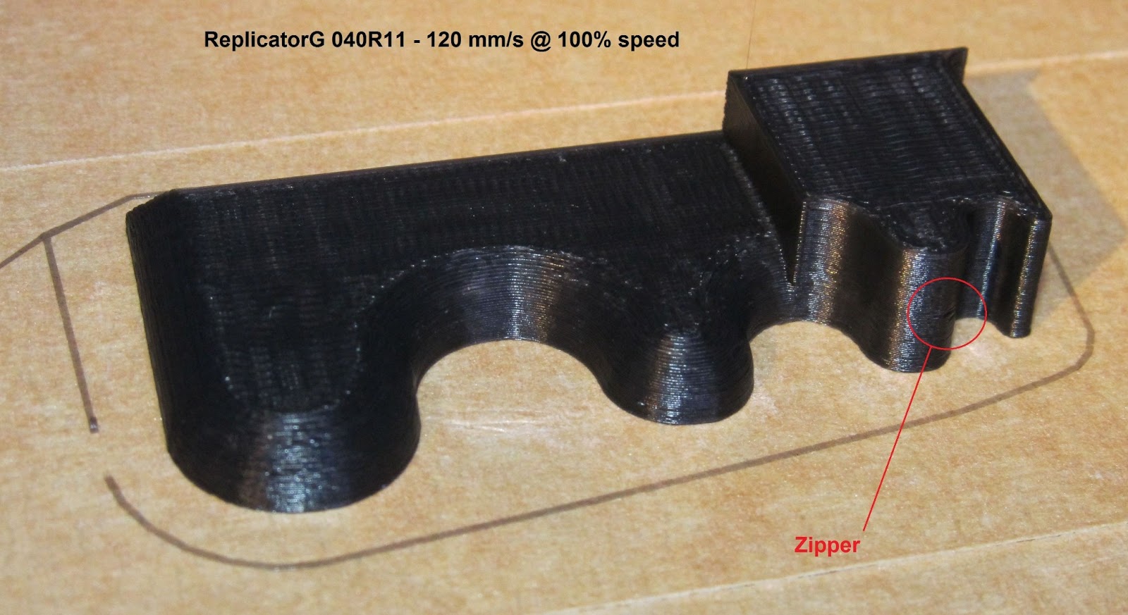
So here is an example of what I would call a real world object - printed at 120mm/s with my replicatorg sailfish profiles. No issues with zippers here, great surface finish, and the results are dimensionally pretty accurate.So i am heading off to Taipei tomowwor for the international bike show - wish me luck!
Enginwiz
funmakerBart
Enginwiz

funmakerBart
funmakerBart

Brian Jones
funmakerBart

Eighty
I recently abandoned the retraction settings in Skeinforge, and moved to firmware deprime, and almost all my zits are gone. The zipper looks much better on single-wall prints too.
Brian Jones
funmakerBart
David Celento
Eighty
funmakerBart
David Celento
More seriously, this is like a bit like a CNC router that does not lift, during a travel, slicing through all the work it just cut.
FEATURE REQUEST: As the Slicer Wars duke it out for primacy, improved craft will undoubtedly win a number of fans. Allow users to enable an option to have "lifts" during travels for delicate objects and/or high quality finishes.
Yes, "lifts" would take longer, but for many quality is more important than speed. Maybe most importantly, this would practically eliminate small elements being "knocked over" during builds.
Eighty
Eighty
David Celento
Last night I did a back to back test of a modified version of MAKE magazine's Torture Test using RepG+Sailfish (using Wincommander's .2 profile), and MakerWare (using Enginwiz's .2 profile).
The layer thickness seems to have differed (neede to exam GCode to be sure), but the MW print worked entirely. The RepG+S print knocked over the arch.
Would like to run test again to confirm a few things. If I find anything useful, will post results.
David Celento
Eighty
David Celento
Eighty
Using the ABS setting, change the filament packing ratio (in the dimension plugin) from 0.85 to 0.97 or so. That alone makes a huge difference.
Then input the measured filament diameter from your spool (using calipers) in Print-o-Matic.
Run a test print of a calibration cube. If it bulges up at the top, increase your filament setting by 0.01-0.02 and try again. Repeat as necessary.
David Celento
David Celento
On Wednesday, March 20, 2013 6:27:04 PM UTC-4, Eighty wrote:
change the filament packing ratio (in the dimension plugin) from 0.85 to 0.97 or so.
Eighty
Eighty
David Celento
Eighty
The filament diameter in the profile is overridden by print-o-Matic. So what you enter in the gcode dialog box will be used (assuming you're using P-o-M).
David Celento
, "layerWidthRatio": 1.482 MW guide indicates this value to be extrusion width / layer height. Thus, it appears that this should be 0.40 / 0.20 = 2. The value of 1.482 is the default value when creating a new profile because default layer height is 0.27. Just wondering if you left this value for a particular reason or possibly might have overlooked this. Not sure why this isn't an automatic calculation, or why one would adjust this. Insights?
David Celento
Eighty
Here's an MBI article on it.
http://www.makerbot.com/support/replicatorg/documentation/printomatic/
Dan Newman
On 22 Mar 2013 , at 1:03 AM, David Celento wrote:
> So.... what exactly does Print-o-Matic do in RepG+SF? Based on my
> understanding of the above, it should simply over-ride the already
> specified values in the selected Slicing Profile? And one need not use it,
> right?
show you everything Print-o-Matic overrides in SF.
Dan

joe...@gmail.com
You received this message because you are subscribed to the Google Groups "MakerBot Operators" group.
To unsubscribe from this group and stop receiving emails from it, send an email to makerbot+u...@googlegroups.com.
For more options, visit https://groups.google.com/groups/opt_out.
Eighty
Enginwiz


David Celento
David Celento
Enginwiz
Enginwiz

Enginwiz

David Celento
As a test, in RepG+SF, run two prints:
A) set PoM values as they are in Henry's profile.
B) just use Henry's profile, but turn PoM off.
Should be identical results printed, right?
When I tried this, my prints were very different. Either I screwed up something, or is it possible that there is a glitch somewhere in the matrix?
Enginwiz
Dan Newman
> Again I get 2 zippers - one on the right and one on the left side.
> The two invisible vertical surfaces on the back of the cube are perfect.
the extrusion of one layer ends, the Z coordinate is increased, and
the next layer then begins. So, with that definition in mind, have you
looked in the gcode and confirmed that you actually have two spatially
separated zippers? It's certainly possible to achieve that and they
would have an alternation similar to what I think I'm seeing. I'm
just seeking confirmation that that is what you have as opposed to
some other artifact which is causing those effects. For example,
I've seen SF do odd things where it starts breaking line segments
into a long run and a short run. And then, if you have it running
alternate layers in opposite directions then you can get surface
effects similar to what you seem to have.
Dan
Enginwiz
Tomorrow I will copy the gcode into Repetier Host and check the extruder moves.
Thank you for this hint. Could be a slicing error of Skeinforge.
I will also try to reduce deprime to 16 as suggested.
Robert

Andy Chen
About the clip module. I interpreted from the docs that clip is used to increase the perimeter gap to address bulging. Henry, one of your posts suggests that clip is used actually used to for the opposite purpose, to decrease the gap. Either way, by turning off clip you also lose its loop connecting feature.
David Celento
David Celento
Enginwiz
Enginwiz


Joseph Chiu

Matthew Stonebraker
On Tuesday, March 26, 2013 3:35:28 PM UTC-4, Enginwiz wrote:
Sorry - the screenshot of Repetier Host looks too bad. Converting it to JPG destroyed most of the detail.Here comes a better one.
And an additional detail of the left side.
Enginwiz


Eighty
Enginwiz
I did some measurements on the Replicator 2 for Bottleworks and bought a set of his modified Replicator 1 arms.
These were prototypes for the Replicator 2 and needed some filing and shimming. Anyway my Z-stage
is now more solid than the 10 mm Z-rods. His redesigned arms for the Replicator 2 / 2X look even better
and will be easier to install.
Wingcommander Henry requested a deprime value of 64 in onboard preferences - advanced for his sailfish
profiles published March 2013. In his latest profiles used for this test he switched back to 16 and my Rep 2
has this value of 16 in onboard preferences - advanced.
Enginwiz
You can see that on the first picture showing both prints.
I have a "JANSJÖ" clamp on LED spot lamp from IKEA
mounted on the frame of my Replicator 2 to illuminate
the immediate print area around the nozzle. This LED lamp
produces the shiny effect on the black PLA.
The PLA blend used for this test is Natureworks 4032.
I buy it on www.fabber-parts.de.
