Can't get thin walled objects to print correctly, Help Needed

DiyAddicts
AM
DiyAddicts

ddurant
little high.. It also looks like the prints start ok then go sorta
pear shaped. It could be that you're warming up to a good temperature
but have skeinforge set to a higher one, which messes things up as the
print progresses and the temp reaches the set value.
Also, your pix are all of the sides of objects but the term 'wall
thickness' sorta only applies to views from the top.
> it seems like it is not coming up far enough and dragging through the whole object
Too much plastic = turn feed rate up a little; too little plastic =
turn feed rate down a little. I'd get the temperature sorted first
though, because the prints do start out ok then go south.
> I hope everyone had a great New Years!

The Ruttmeister
tension..

Charles Edward Pax
Charles Edward Pax
blog: http://charlespax.com/
twitter: http://twitter.com/charlespax
> --
> You received this message because you are subscribed to the Google Groups
> "MakerBot Operators" group.
> To post to this group, send email to make...@googlegroups.com.
> To unsubscribe from this group, send email to
> makerbot+u...@googlegroups.com.
> For more options, visit this group at
> http://groups.google.com/group/makerbot?hl=en.
>
DiyAddicts
>On Sunday, January 2, 2011 8:36:43 PM UTC-6, Charles Edward Pax wrote:
Which version of Skeinforge are you using?
I am using Skeingorge 35 that is packaged in RepG 23
DiyAddicts
>What temperature are you running at?
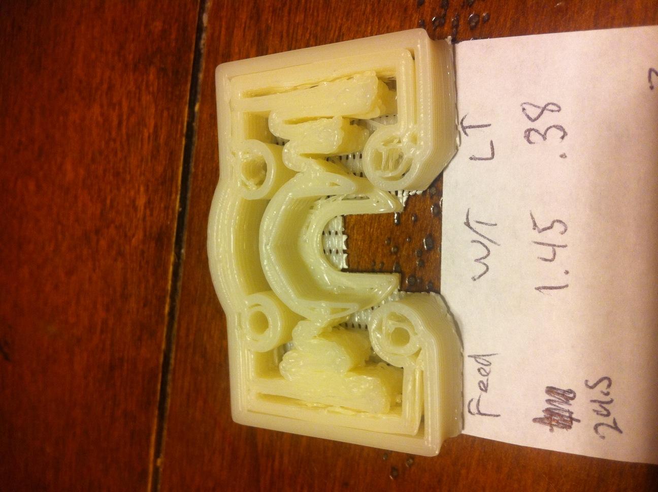
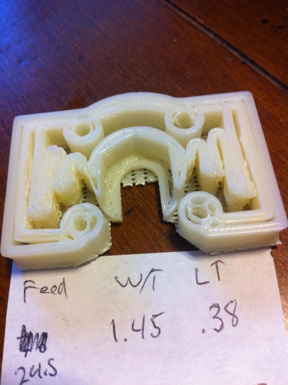
I spent about four hours last night printing test android arms. I have gotten a lot closer I think, but I am honestly a little stumped on what got me closer and what to keep tweaking. After about 15 prints I got the attached pictures with the following settings:
Feed rate: 30
w/t: 1.57
layer thickness: .38
It now looks like they are starting off very bad and then finishing up ok. It does look like the feed rate might be a little high by looking at the tops.
>It could be that you're warming up to a good temperature
but have skeinforge set to a higher one, which messes things up as the
print progresses and the temp reaches the set value.
I appreciate the help everyone.
ddurant
> temperature is during the print?
temperature but it caused problems so they removed it. Hopefully, it
will find its way back in someday - I miss the option (but not the
problems!)
Use a text editor to open up one of the gcode files you're printing
and search for "M104" (set extruder temperture) and "M109" (set HBP
temperature) commands. They'll look something like "M104 S210 T0",
which sets the extruder to 210C.
Do the temperatures settings in the gcode look correct to you? What
sort of values do you see in there?
> Feed rate: 30
The problem could also be that you're printing too a little too slowly
- low feed rates can have more trouble with overhangs than higher
ones. 30 isn't overly slow but it's certainly not fast.
Have you tried printing something that's thin-walled but does not have
overhangs? http://www.thingiverse.com/thing:3057 might be a good test
object.
> 200KViewDownload
>
> photo 2[1].JPG
> 170KViewDownload
DiyAddicts
>Use a text editor to open up one of the gcode files you're printing
and search for "M104" (set extruder temperture) and "M109" (set HBP
temperature) commands. They'll look something like "M104 S210 T0",
which sets the extruder to 210C.
Do the temperatures settings in the gcode look correct to you? What
sort of values do you see in there?
>The problem could also be that you're printing too a little too slowly
- low feed rates can have more trouble with overhangs than higher
ones. 30 isn't overly slow but it's certainly not fast.
>Have you tried printing something that's thin-walled but does not have
overhangs? http://www.thingiverse.com/thing:3057 might be a good test
object.

Aaron Double
On Jan 3, 8:32 pm, DiyAddicts <adam_mar...@att.net> wrote:
> >Use a text editor to open up one of the gcode files you're printing
>
> and search for "M104" (set extruder temperture) and "M109" (set HBP
> temperature) commands. They'll look something like "M104 S210 T0",
> which sets the extruder to 210C.
>
> Do the temperatures settings in the gcode look correct to you? What
> sort of values do you see in there?
>
> M104 is at 225 and M109 is at 125
>
> >The problem could also be that you're printing too a little too slowly
>
> - low feed rates can have more trouble with overhangs than higher
> ones. 30 isn't overly slow but it's certainly not fast.
>
> I had been printing at 22 mm/sec and getting pretty good results. (I got
> that number from measuring the extrusion as posted on the makerbot blog I
> believe it was). But I am up to trying anything :)
>
> >Have you tried printing something that's thin-walled but does not have
>
DiyAddicts
AM

Danial
DiyAddicts
AM
ddurant
Is it just the way ABS takes pictures or does the right side of each
one of those sorta curve in on itself? If they are curving in, your
temperature is too high - try dropping it to 215 and seeing how that
works.
I think you're actually not too far off but your thread width is too
big to print that part correctly - sorry, I'd forgotten just how thin
those walls are. As Aaron said, that's a tricky Thing to print. That
used to be my thin-wall test piece but it's been a while since I've
printed one..
It looks like you're poking at width over thickness. Make sure you do
both perimeter w/t in Carve and infill w/t in Fill, unless you know
you want different values.
> 189KViewDownload
>
> photo 2.JPG
> 179KViewDownload
>
> photo 3.JPG
> 179KViewDownload
>
> photo 4.JPG
> 202KViewDownload
>
> photo 5.JPG
> 175KViewDownload
Danial
DiyAddicts
one of those sorta curve in on itself? If they are curving in, your
temperature is too high - try dropping it to 215 and seeing how that
works.
>I think you're actually not too far off but your thread width is too
big to print that part correctly - sorry, I'd forgotten just how thin
those walls are. As Aaron said, that's a tricky Thing to print. That
used to be my thin-wall test piece but it's been a while since I've
printed one..
>It looks like you're poking at width over thickness. Make sure you do
both perimeter w/t in Carve and infill w/t in Fill, unless you know
you want different values.
AM
ddurant
temperature is too high..
> When you say my thread width is too big...
I had a really long winded answer going then changed my mind..
Can you do one more try at that object with the 3 "Extra Shells"
settings in Fill set to 0?
DiyAddicts
settings in Fill set to 0?
ddurant
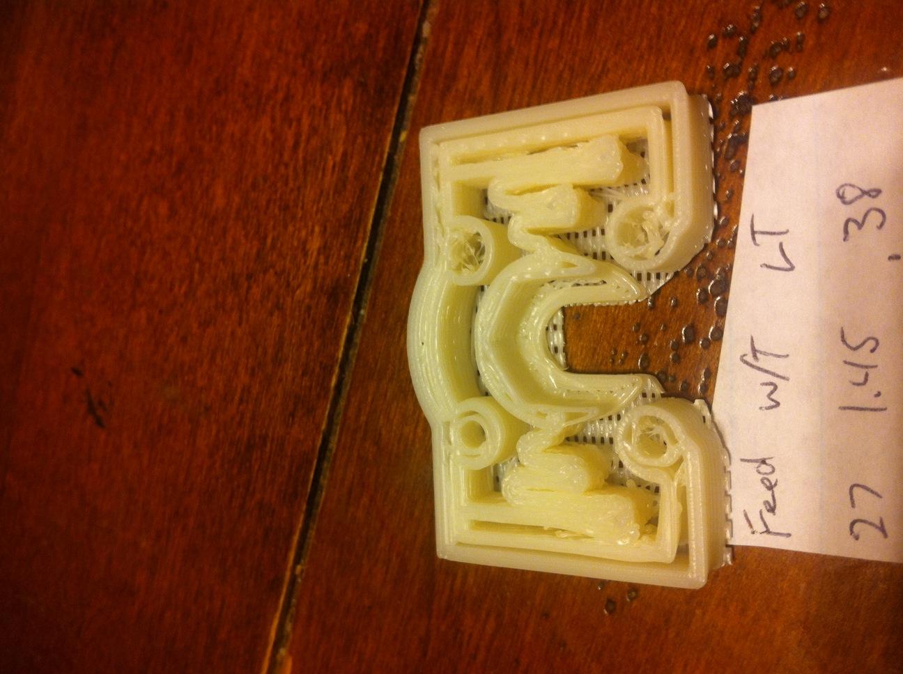
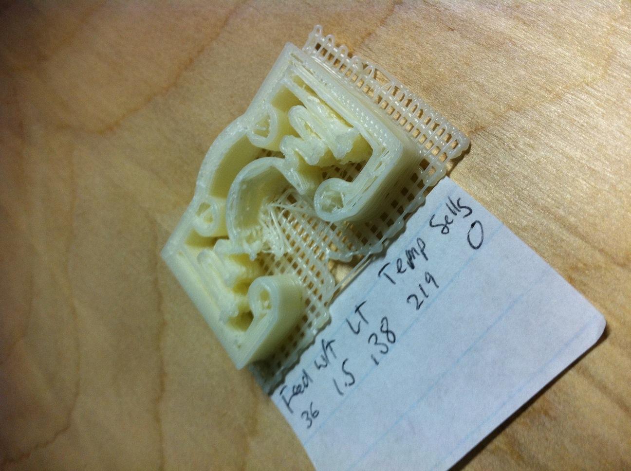
Notice the bits on the bottom of that one - the arms that end in the
bolt holes. Those arms should be solid but the picture shows a gap in
the wall.
Turning off the extra shells leaves skeinforge enough room to fill in
that gap. Even though the shells=0 version is a bit of a leaning
tower, I think it's still the "more correct" print. (In general, btw,
I leave the extra shell settings where they are and only turn them
down for Things that have very thin walls.)
A print leaning like that usually means you have hardware slipping. I
really don't know much about ToMs but the most common causes for that
are belts being too loose or the nozzle catching on plastic blobs.
Could also be that the pot on that stepper driver is turned down too
low. The print doesn't look very blobby to me so I'd check that you
don't have any loose belts then maybe turn that one stepper up a
little bit.
Did you turn the temperature down a bit? Did that help or make things
worse?
> 205KViewDownload
>
> photo 1.JPG
> 172KViewDownload

Zip Zap
Anyone have any suggestions on how to print out DXF files on paper? I've got Turbo Cad but having problems getting anything to print out.
DiyAddicts
worse?
>A print leaning like that usually means you have hardware slipping. I
really don't know much about ToMs but the most common causes for that
are belts being too loose or the nozzle catching on plastic blobs.
Could also be that the pot on that stepper driver is turned down too
low. The print doesn't look very blobby to me so I'd check that you
don't have any loose belts then maybe turn that one stepper up a
little bit.
AM
DiyAddicts
Regards,
AM

Achilles Boiser
ddurant
pretty sure that's not caused by a mechanical issue like loose belts
or the nozzle catching on a blog, I'd turn up the pot on the stepper
driver. That will give it a little more push, which you may need for a
print like this.
> ...was caused from the change to the shells
Yes but not exactly. Fewer shells meant it was able to do the infill
and the infill on that object is pretty thin. Lots & lots of little
zig-zags, which may be too much for the pot setting you're at now.

Joheinz
Markus
2011/1/5 Achilles Boiser <achille...@gmail.com>:
> Anyone have any suggestions on how to print out DXF files on paper? I've
> got Turbo Cad but having problems getting anything to print out. I'm trying
> to print out the DXF files for the ThingOMatic.
>
> --
> You received this message because you are subscribed to the Google Groups
> "MakerBot Operators" group.
> To post to this group, send email to make...@googlegroups.com.
> To unsubscribe from this group, send email to
> makerbot+u...@googlegroups.com.
> For more options, visit this group at
> http://groups.google.com/group/makerbot?hl=en.
>
--
http://justjoheinz.posterous.com/
http://softwarepoets.org
http://twitter.com/joheinz
Aaron Double
correctly to talk about dxf files?
Can't you make your own post about that subject?
On Jan 5, 12:25 am, Joheinz <justjohe...@googlemail.com> wrote:
> Try Qcad, it has good DXF support.
> Markus
>

Z LeHericy
//((=:Z:=))\\
INVENTIONS
Technologies
zinventions.com
DiyAddicts
pretty sure that's not caused by a mechanical issue like loose belts
or the nozzle catching on a blog, I'd turn up the pot on the stepper
driver. That will give it a little more push, which you may need for a
print like this.
When set to 225C and extruding at full PWM it would constantly swing from 217C to 235C
When set to 216C it would swing from 208C to 218C.
I don't know what the acceptable temperature variations are, but these seem like a lot to me. I would like some feedback, but I'm guessing it is time to start chiming away at the PID settings.
ddurant
know little about - others here understand it, though.
Unless the temperature is causing blobs (unlikely) and the nozzle is
catching on them, that axis slip really probably is a pot that's
turned down too low.
DiyAddicts
know little about - others here understand it, though.
>Unless the temperature is causing blobs (unlikely) and the nozzle is
catching on them, that axis slip really probably is a pot that's
turned down too low.
Does anybody know how much variance is ok on the extruder temperature?
DiyAddicts
know little about - others here understand it, though.
catching on them, that axis slip really probably is a pot that's
turned down too low.
ddurant
slipping - you even posted a picture of it.
Has anybody else with a ToM tried to get a good print of that wobble
arrestor?

Andrew Plumb
--
You received this message because you are subscribed to the Google Groups "MakerBot Operators" group.
To post to this group, send email to make...@googlegroups.com.
To unsubscribe from this group, send email to makerbot+u...@googlegroups.com.
For more options, visit this group at http://groups.google.com/group/makerbot?hl=en.
Makerbot Number Nine... #9... 0x09... 0o11... 0b1001...
http://clothbot.com/wiki/MakerBotNumberNine
DiyAddicts
slipping - you even posted a picture of it.
DiyAddicts
I had seen that page, but missed those values for some reason. Mine are pretty far off from those so I will try them when I get home. Thanks!
AM
Aaron Double
right. Do you know if it is slipping while printing? or when
traveling? If when printing, I would try slowing your feedrate and
travelrate, if just when travelling, just slow down travel rate.
Something else that might be interesting would be to run it with less
shells and comb turned off. You'll should get a bunch of strings but
you'll have much less travel. (that part will print much faster also)
That part is a pain.
To see an example of the rapid back and forth take a peek at this
video:
http://www.flickr.com/photos/48982649@N07/5324656172/
ddurant
Next thingiverse contest: bobble heads to mount on the top of our
bots!
(don't take offense - my machine shakes waaaay more than that)
>
> - Show quoted text -
Aaron Double
increased, but then it's a chunk of aluminum 110x130x6mm. Had to turn
up the pots on the stepper boards as well. With Rob's PSMD it's at
least quietly shaking...
The bobble head would be funny but I think it would get old in like 5
minutes.
ddurant
> are correct?
movement that usually causes it.
In this one, specific case, those types of movements get put in the
tool path because you turned off the extra shells. You could leave the
extra shells on but then this part doesn't print correctly.
On different objects or maybe even on this object with a very
different profile config, you might get the problem only if you did
*not* turn extra shells off.
If you're not sure what extra shells are any why I suggested you turn
them off, I can go into that. It's good background/theory stuff to
know but it's not really required reading..
ddurant
> minutes.
They wouldn't *have to* be for the top of bots, though. You could put
them on pets or your car dash, too.
DiyAddicts
tool path because you turned off the extra shells.
I'm at the point though to where I can not see anywhere that slipping could be happening. I'll try to shoot a video of the print maybe you can see something that I am not. I do have my travel rate up a little so I will bring that back down and try.
>If you're not sure what extra shells are any why I suggested you turn
them off, I can go into that. It's good background/theory stuff to
know but it's not really required reading..
ddurant
the object. When you print something, you usually see the printer draw
the outline then do lots of zig-zags to fill in the center then move
up and do the next layer. If you use extra shells, it draws more than
one outline around the object.
I think I've heard people say that extra shells adds strength but I'm
not sure I buy that. It seems like a nicely dialed-in profile should
have the same strength regardless of the shells. I could be wrong,
though.
Anyway, when you ask skeinforge to slice up an object, it looks at the
thread height and thread width that you specify (layer thickness and
layer thickness * w/t) then maps out the series of moves needed to
cover the object with threads of that size. Just like Crayons 101,
this is tracing the outline then scribbling to fill the area inside
the outline. Or, if you have extra shells, there are multiple *traces*
around the outline then scribbles.
One of the problems with doing things like this is that it's not
possible to fill areas that are between 2 and 3 times the thread
width. Not with skeinforge anyway.
If you haven't heard the 2-3 thing before, picture a Sharpie marker
that draws a line 1 inch wide. Using that marker and without drawing
over areas that you've already drawn on, can you trace & fill in an
square that's 2 inches wide? Yes - it's just two lines, side by side.
Just the traces around the outline cover the whole area.
A square 3 or more inches wide is also doable. You do the trace around
the edge then fill in the middle. The trace around the square takes up
2 inches then filling in the middle is just zig zagging through the
center.
An area that's more than 2 inches but less than 3 inches wide is a
different story, though. With that sort of area, you eat 2 inches
doing the trace around the outside but are then left with an area
that's less than 1 inch wide in the middle.
When you're using a marker, this really isn't that big of a deal - you
cheat and draw over an existing line. When you're extruding plastic,
it is a big deal. You can't just pump more plastic into the area
because it would blob up and cause all sorts of problems. You could
have software that looked for this sort of issue and did clever things
to decrease the thread width but, well, we don't have that software.
What skienforge does is leave that area blank. All your wobble
arrestor pictures (except the leaning one) show this issue - areas
that should be solid are left with big holes in the middle. Look
closely at just the top layer of the leaning one and compare it to the
tops of some of the others.
Once you sorta get that straight in your head (it took me a few tries
when I first heard about this), you can see why some objects are
sensitive to the number of extra shells: one extra trace around the
edge changes the 2-3 rule into a 4-5 rule because it eats up 2 more
threads widths (one on each side of the area being filled) and changes
where your limit is for filling in the center.
Not sure if that all makes sense - I tend to ramble - but I'm outta
time for now..
Aaron Double
Aaron Double
be springy. That's how the flexmount for the nut on the Z-rider works.
Aaron Double
ddurant
DiyAddicts
One thing I have started noticing tonight is that when the HBP is heating is causes the DC extruder motor to drop pitch in sound, like it is slowing down some. Then as soon as the HPB led kicks off it kind of revs back up. It is almost impossible to tell how much it is actually slowing it down though.
I will have some more time this weekend to dive into things more. Again, thanks for all the help
ddurant
Sorta the whole point was that the leaning you saw when you turned off
extra shells wasn't really about there being extra shells on the
object or not. Turning off the extra shells just left skeinforge
enough room to fill in the center of the arms on the object and the
moves needed to do that fill triggered the lean.
Your X or Y is indeed slipping. Maybe it only slips when you're doing
a difficult print like this one with lots of back & forth scribbles
but it is slipping and this will likely come back and bite you on some
other object. It could be that some other object slips when extra
shells are at their default settings. Or it could only happen when you
turn them up. Or down.
Feel free to ignore it for now if you want but keep in mind that
there's some threshold of some behavior that will make an axis slip. A
Cupcake is totally able to print that part correctly so I assume a ToM
can do it too. The trick will be figuring out what's causing the slip
then either how to fix it or how to avoid it in the future. This
doesn't need to be solved today but you should track it down and
squash it at some point.
> One thing I have started noticing tonight is that when the HBP is heating is
> causes the DC extruder motor to drop pitch in sound, like it is slowing down
> some
soon for all the people reporting motor/power troubles. A working
extruder isn't really an optional bit on a 3D printer.
I wonder if that wobble arrestor still slips with 0 shells if you
disable the HBP. Maybe the system sorta losing power making the
steppers more likely to slip steps...

Ed Nisley
> The trick will be figuring out what's causing the slip
> then either how to fix it or how to avoid it in the future.
Having fought this issue to a standstill on my Sherline CNC milling
machine, I think I know what's behind the "slipping" issue.
The problem is *not* that the belts slip on the pulleys. If that
happened, the extruder position would suddenly jump by an integer
multiple of the belt's 2 mm tooth pitch. An abrupt 2 mm offset in a
printed object would be painfully obvious.
What's really happening is that the extruder firmware doesn't
accelerate / decelerate the motors (as of the last time I looked at the
code, anyway). Instead, it assumes the motors can begin turning at
whatever step rate is required for the current motion and stop turning
when that pulse train ceases, with the carriage obediently following
along.
That's a good assumption for a machine with moderately beefy steppers,
good drivers, low-mass carriages, and low-friction/low-stiction guides.
Larger machines must ramp the motor / carriage velocity up and down,
limiting the acceleration at both ends of the motion to whatever the
hardware can handle.
The simplifying assumptions that permit bang-bang starts and stops are
true for the TOM (and Cupcake), except for friction / stiction. Despite
those lovely bronze bushings, it's entirely possible to build a TOM with
an X (or Y) carriage that the motors can move only with great
difficulty: I've done it!
The symptom is exactly what you're seeing: the commanded position
doesn't track the actual position, because the carriage doesn't start
moving until the motor manages to break it free from the stiction. Those
"lost steps" can never be made up, because the TOM doesn't know anything
about the actual carriage position.
In addition, the TOM stepper controllers use quarter-step drive, which
produces smoother motion at the cost of lower starting torque. Lower
torque = less force = lower maximum acceleration = less tolerance for
stiction.
Why it happens mostly in the X direction:
The X carriage (MBI calls it a "stage") slides on two rods, each of
which is fixed at four places: both ends of the Y carriage and both ends
of the X carriage. If the rod-to-rod spacing in those four places isn't
*exactly* equal, then the X carriage bushings will bind on the rods.
Alas, tolerance creep in the plywood and maybe a bit of off-center
sanding when you fitted the bushings into the plywood can produce
exactly that situation.
How to diagnose on X and Y:
Dismount the drive belt (which will probably require dismounting the
motors or their drive pulleys) so the carriage can slide without turning
the motor.
If you can bat the carriage back and forth along the entire length of
its rods by tapping (*not* pushing) with your fingertips, it's all good.
In my TOM, moving the X carriage required quite a shove and it
definitely didn't slide freely at all.
How to adjust the X carriage:
Take the entire X and Y assembly out of the TOM (sigh). Remove the rod
end caps on both ends of the rear rod. Slide the X carriage to the right
end, then push the rear rod out of the right end piece toward the left
(push it into the plywood) while supporting the X carriage. Most likely,
the rod will go *spung* a fraction of a millimeter horizontally (you
control the vertical offset by supporting the carriage).
That's the rod's way of telling you that the end hole is in the wrong
position. If it slides easily in and out of that hole, then it's all
good; go to the left end as below.
Sand the offending side of the hole (wrap sandpaper around a small rod
so it almost completely fills the hole) until the rod slides easily into
the hole.
Slide the carriage to the left end and repeat that process.
Replace both end caps.
The carriage should now slide back and forth with just finger taps.
If you overdo the sanding, shim the loose side of the holes with
aluminum foil and a dab of adhesive. If the rod rattles around, that's
bad; add an all-around shim and put a very thin slice of foam under the
end cap to calm it down.
How to adjust the Y carriage:
The right side of the Y carriage rides on bushings and the left side
rides on three ball bearings, making it not quite so sensitive to
misalignments. Check for free motion when you reinstall the assembly
and, if it's off, adjust the right-hand rod, because the ball bearings
don't capture the rod all the way around.
Those bronze bushings work wonderfully well, but only when the rods are
exactly parallel!
Hope that helps...
Aaron Double
I printed some wobble arresters (not my arrester, natetrue's version,
same one you have been playing with) yesterday as calibration objects
for PLA.
I figured you might be interested. I am using a very modified cupcake
though, not a T-O-M.
That being said, it took me about 5months to start getting prints that
I was happy about (got my bot in Feburary 2010).
Just be patient, and you will be rewarded with good prints.
http://www.flickr.com/photos/48982649@N07/sets/72157625644168515/
I have a really dumb question, how do you upload an image into a post?
I haven't been able to find the instructions anywhere.

Koen Kooi
Op 7 jan 2011, om 19:05 heeft Aaron Double het volgende geschreven:
> Hey DiyAddicts,
>
> I printed some wobble arresters (not my arrester, natetrue's version,
> same one you have been playing with) yesterday as calibration objects
> for PLA.
>
> I figured you might be interested. I am using a very modified cupcake
> though, not a T-O-M.
>
> That being said, it took me about 5months to start getting prints that
> I was happy about (got my bot in Feburary 2010).
>
> Just be patient, and you will be rewarded with good prints.
>
> http://www.flickr.com/photos/48982649@N07/sets/72157625644168515/
>
>
> I have a really dumb question, how do you upload an image into a post?
> I haven't been able to find the instructions anywhere.
This is a mailing list, so you can just attach it to the mail :)
regards,
koen
Aaron Double
just look at it through the webpage. Maybe I need to adjust my
settings.
Thanks!
ddurant
I know you've got Robs stepper driver on your bot - did you go for
1/16th steps on X & Y? I did on mine but haven't installed it yet.
Ed's post about steppers has made me a little nervous..
> This is a mailing list, so you can just attach it to the mail :)
instead! :P
AARON DOUBLE
Yes, I have Rob's PSMD running at 1/16th step, I feel like I have more torque with this over the makerbot old school steppers and I've been running it for about 5 hours today and the X stepper is not ever warm to the touch.
I also don't have the pots turned up. One of the interesting things that came out of this is the steppers are so quiet now that it's slightly musical, definitely different tones happening, I find it fun, my wife liked the louder buzzing more, easier for her to tune it out. I turned up the current a bit to make her happy.
DiyAddicts
extra shells wasn't really about there being extra shells on the
object or not. Turning off the extra shells just left skeinforge
enough room to fill in the center of the arms on the object and the
moves needed to do that fill triggered the lean.
> Your X or Y is indeed slipping. Maybe it only slips when you're doing
a difficult print like this one with lots of back & forth scribbles
but it is slipping and this will likely come back and bite you on some
other object. It could be that some other object slips when extra
shells are at their default settings. Or it could only happen when you
turn them up. Or down.
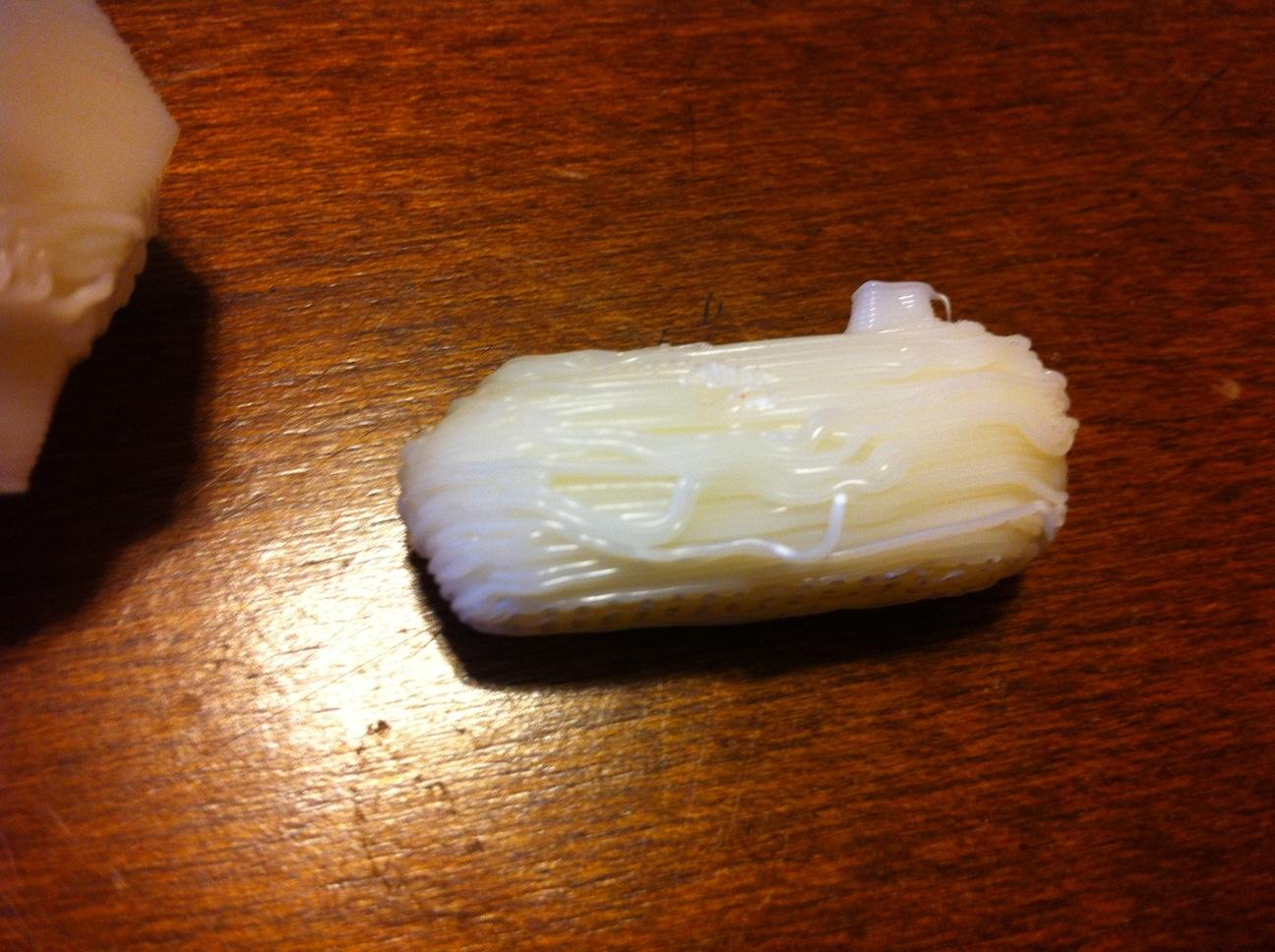
photo1 attached attached is with 0 shells. There is not near enough plastic, but at least it printed without a lean!
>Wow. That's.. uh.. not very good. Hopefully MBI will have a solution
soon for all the people reporting motor/power troubles. A working
extruder isn't really an optional bit on a 3D printer.
I am still noticing my extruder slowing down (audibly) every time HBP kicks on to heat. So I figured I would turn it off and see what happened. Now with the HBP turned off the extruder still slows down but it much shorter burst. I moved some wires so I could see the extruder heater led, and now that I can see it, it shows that every time that heater kicks on it is also slowing down the extruder.
ANOTHER odd thing is when I have my HBP off my temp values on my extruder go up about 6 degrees and fluctuate from there. When I have it on my extruder temp barely gets above my set value (219)
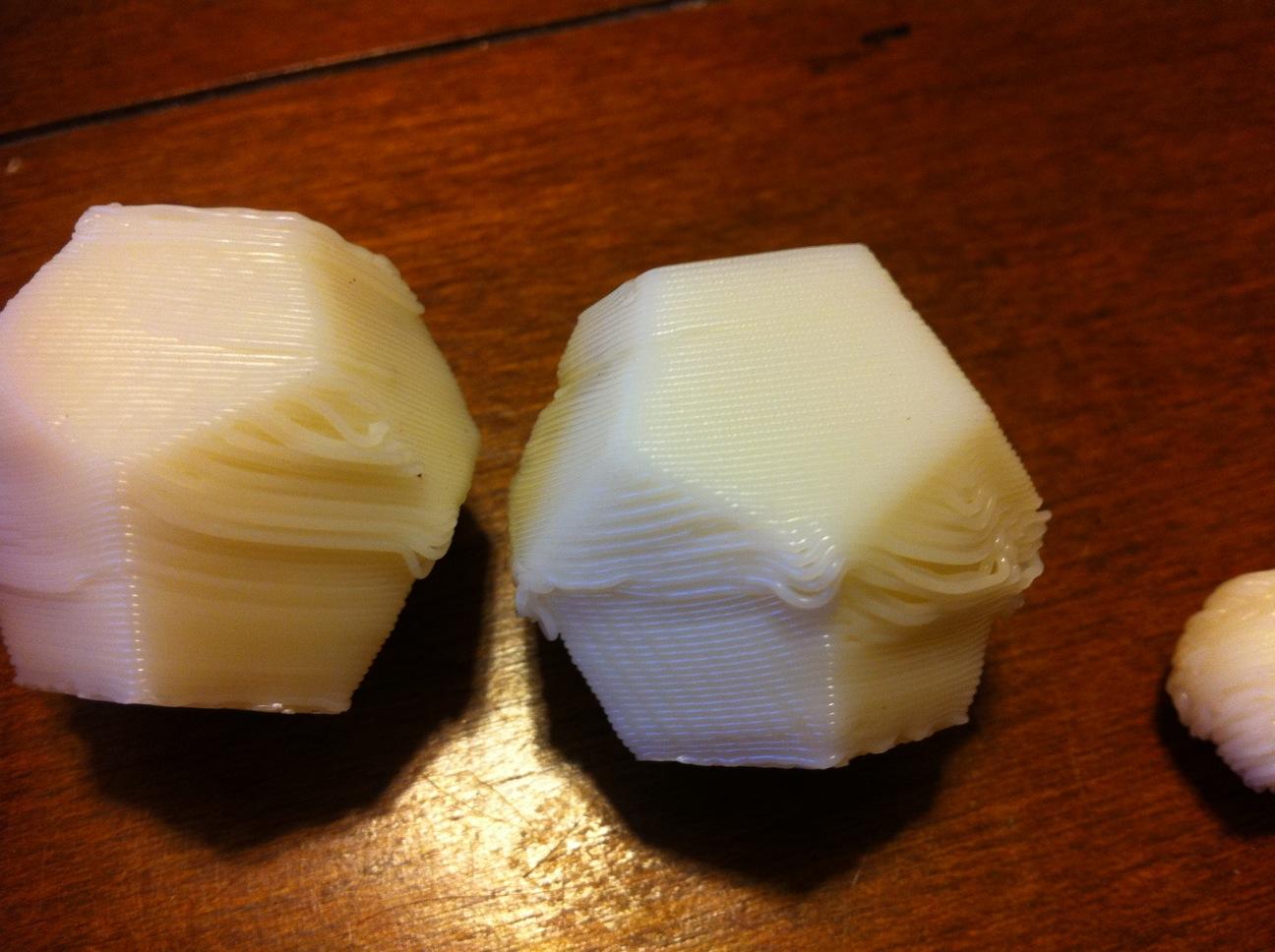
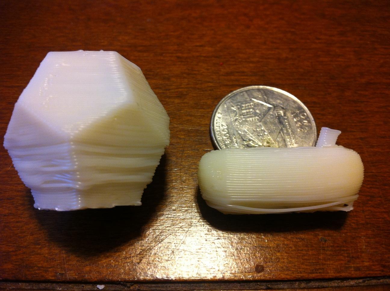
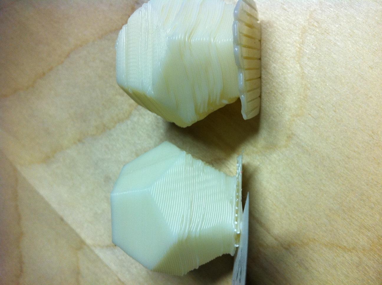
So I am still trying with very little luck to get things dialed in. The one thing I don't know though is a 7-8 degree swing in extruder temperature too much? The second photo attached is of the dodecahedron, the one on the left is as close as I have been able to get. Right one is where I started out a couple weeks ago. The main flaw in the print is always in the lower half which you can see.
The settings on the left dodeca are:
Feed: 35
w/t: 1.5
LT: .38
shells: 2
Temp: 219
I didn't get a picture of the top of it, but I can say it is a little sparse on top.
DiyAddicts
> That being said, it took me about 5months to start getting prints that
I was happy about (got my bot in Feburary 2010).
AM
AARON DOUBLE
1. My build platform is now pretty heavy, so slinging it back and forth rapidly throws the whole makerbot around. It's a fairly large sized chunk of aluminum.
2. I'm now only doing one threaded rod. The center point on the nut on the threaded rod is at the same point (directly behind) as the tip of the mk5 nozzle. Since the mk5 is kinda tall and the weight is mostly on the top, when the makerbot is thrown around by really quick movements in the X-axis, the platform will rotationally vibrate with the nozzle tip as the center point, I actually designed it to do this. (I just didn't think it would work as well as it does)
The rotational vibration is the drawback of only having one vertical load point. I would love to know if anyone with a T-O-M sees this as well. I didn't notice it in action until recently because the prints weren't screwed up.
The other thing that is kinda built in is, since the platform is cantilevered from the back, there is a bit of vertical play that only shows up when there is an obstruction. In other words, if you have a really big blob the nozzle tip will just lift up a little bit and go over the blob and not tear the print off the platform. After a couple layers the blob is incorporated in the part. The blobs for me are because I have yet to put a Z endstop in place, if I screw up my starting height there is a chance of blobs.
On Jan 10, 2011, at 9:12 AM, coasterman-1674 wrote:
> If the X or Y is skipping, I would check belt tension, stepper
> parameters, and then adjust the Skeinforge settings until you can fit
> the extra shells in a dodecahedron so it draws with four lines. I
> think the goal here is to be able to smoosh 4 lines into 2mm of space.
> That will ease any zigzagging.
>
> And then the bobblehead makerbot, how funny. Make a Makerbot with a
> bobbling Z-stage. I laughed my head off seeing the next contest as a
> bobblehead as a joke. I'm not exactly sure if the Z should bobble like
> that, though. Mine never bobbles.
ddurant
fills thin areas.
The part about the nut being level with the nozzle is interesting..
I'm wondering how that'll work with the makergear extruder. Also now
wondering about balance, since that stepper extruder has 90% of its
weight off to one side...
AARON DOUBLE
DiyAddicts
parameters, and then adjust the Skeinforge settings until you can fit
the extra shells in a dodecahedron so it draws with four lines. I
think the goal here is to be able to smoosh 4 lines into 2mm of space.
That will ease any zigzagging.
DiyAddicts
AARON DOUBLE
On Jan 10, 2011, at 8:57 PM, DiyAddicts wrote:
> >About the bobble, it is coming from two things.
>
> Sorry, was that reply to me or ddurant? Thread is getting a decent size and hard to tell what is where :)
>
Zip Zap
From: DiyAddicts <adam_...@att.net>
To: make...@googlegroups.com
Sent: Mon, January 10, 2011 4:39:53 PM
Subject: [MakerBot] Re: Can't get thin walled objects to print correctly, Help Needed
DiyAddicts
I was thinking since the only part of the model that is having problems is the bottom that maybe the top portion was leaving its shifted layers on the inside. So I took a hacksaw after a couple last night to check and the inside walls look perfect all the way up... I don't have enough experience with all this yet so it is hard to come up with anything else that could be causing this.
AM
AARON DOUBLE
It might be a bit of an environmental temperature problem. What I mean is, is the room cold? If it's chilly, ABS will warp more. Especially on overhangs
DiyAddicts
> It might be a bit of an environmental temperature problem. What I mean is, is the room cold? If it's chilly, ABS will warp more. Especially on overhangs
AARON DOUBLE
On Jan 11, 2011, at 7:27 PM, coasterman-1674 wrote:
>> Then set your Thread Sequence Choice at the bottom of fill to Loops > Perimeter > Infill.
>>
>> What that'll do is draw the inner outline first, then the outer outline then the infill. Having the inner outline first can help secure the outer outline (the one you care about) and minimize drooping and curling.
>
> And hide layer changes!
DiyAddicts
AM
DiyAddicts
Thanks,
Adam
Z LeHericy
--
You received this message because you are subscribed to the Google Groups "MakerBot Operators" group.
To post to this group, send email to make...@googlegroups.com.
To unsubscribe from this group, send email to makerbot+u...@googlegroups.com.
For more options, visit this group at http://groups.google.com/group/makerbot?hl=en.
DiyAddicts
AM
Z LeHericy
You added a couple mm to what exactly in the raft? The only thing I see you can increase directly is the raft margin.
AM
--
You received this message because you are subscribed to the Google Groups "MakerBot Operators" group.
To post to this group, send email to make...@googlegroups.com.
To unsubscribe from this group, send email to makerbot+u...@googlegroups.com.
For more options, visit this group at http://groups.google.com/group/makerbot?hl=en.
DiyAddicts
Anyways, I don't see how the raft margin would help my prints since they are not warping off the platform at all? The just start curving up a bit after around 5 layers.
Thanks
Am
Z LeHericy
--
You received this message because you are subscribed to the Google Groups "MakerBot Operators" group.
To post to this group, send email to make...@googlegroups.com.
To unsubscribe from this group, send email to makerbot+u...@googlegroups.com.
For more options, visit this group at http://groups.google.com/group/makerbot?hl=en.
DiyAddicts
Thanks!
AM
DiyAddicts
ddurant
DiyAddicts
Z LeHericy
I tried the temperature idea and it actually made the problem a lot worse... Just confusing lol. I guess I could try the temperature in the other direction, but I have already been to 140 and I don't know the limit of the HBP. In my mind that is plenty hot
--
You received this message because you are subscribed to the Google Groups "MakerBot Operators" group.
To post to this group, send email to make...@googlegroups.com.
To unsubscribe from this group, send email to makerbot+u...@googlegroups.com.
For more options, visit this group at http://groups.google.com/group/makerbot?hl=en.
ddurant
extrude with it via the control panel, I'd even try 210. In some ways
"it works well" is a lot more important than "it's what other people
use" is here. I usually run at 210 but I have a makergear hot end.
> HBP at 125 until these last few runs
little on the warm side. You really don't want it any higher than it
needs to be.
ddurant
> around 5 layers.
Got a picture?
DiyAddicts
extrude with it via the control panel, I'd even try 210. In some ways
"it works well" is a lot more important than "it's what other people
use" is here. I usually run at 210 but I have a makergear hot end.
> HBP at 125 until these last few runs
little on the warm side. You really don't want it any higher than it
needs to be.
DiyAddicts
I will try to get one in the morning with my camera at work. I can't get my iphone4 camera to get clear enough that close.
AM

Matt
DiyAddicts
> Got a picture?
Attached. But I really couldn't get a good shot of it, maybe you can make something out of it though :)
Also here is a quick video I shot of what it is doing. (sorry it was also taken on my iphone)
http://www.youtube.com/watch?v=voCNmfDu0b0
I have ALL weekend to work on this now so I am up for any ideas.
AARON DOUBLE
--
You received this message because you are subscribed to the Google Groups "MakerBot Operators" group.
To post to this group, send email to make...@googlegroups.com.
To unsubscribe from this group, send email to makerbot+u...@googlegroups.com.
For more options, visit this group at http://groups.google.com/group/makerbot?hl=en.
<photo1_011511.JPG>
AARON DOUBLE
Aaron Double
DiyAddicts
Thanks
AM
Aaron Double
I had never printed the dodecahedron out so I decided to give it a shot and see what the deal was. That thing is a pain, here's my little process for it.
First one was set to:
temp: 220
1 extra shell per layer
infill set to .3
multiply: 1
Came out just like your images, maybe a bit worse
Second:
temp: 220
1 extra shell per layer
infill set to .3
multiply: 2
Was going just like the first, so I cancelled it about 6mm into it.
Third:
temp: 210
0 extra shell per layer
infill set to .3
multiply: 2
Looks pretty promising, still a little bit of curl.
Fourth:
temp: 205
0 extra shell per layer
infill set to .05
multiply: 2
Better than the last but still a bit of curl.
Fifth:
temp: 205
0 extra shell per layer
infill set to .05
multiply: 2x2 (4 printed)
Curl almost gone
My conclusion, when there is an overhang on the part and there is a thin wall and there are extra shells - the plastic doesn't have time to cool down enough. Since we are using motors and not steppers, the cool function will not work except for orbit (but then you would spend a hell of a lot of time cleaning up your parts) warping might happen. Making more than one gives time for each layer to cool down and starting at a lower temp makes the part cool faster as well.
If the images don't load they are at:
http://www.flickr.com/photos/48982649@N07/sets/72157625832411124/
Aaron Double
I'm looking forward to stepper extruders.
> 705KViewDownload
>
> Screen shot 2011-01-15 at 8.25.42 PM.png
> 503KViewDownload
>
> Screen shot 2011-01-15 at 8.25.55 PM.png
> 735KViewDownload
>
> Screen shot 2011-01-15 at 8.26.07 PM.png
> 672KViewDownload
>
> Screen shot 2011-01-15 at 8.26.21 PM.png
> 723KViewDownload
>
> Screen shot 2011-01-15 at 8.27.45 PM.png
> 532KViewDownload
DiyAddicts
I am just about to start a print based on your last settings. I will let you know how it goes.
AM
Aaron Double
Say you want extra shells because your print needs to be tough and waterproof and... tough.
Just put a fan on it while it builds. Will freeze the plastic so it won't curl. There's a reason there's a fan port on the EC.
Aaron Double
temp: 220
1 extra shell per layer
infill set to .3
multiply: 1
> 1246KViewDownload