MOSFET Design Issues
137 views
Skip to first unread message

Anthony Cooper
Jul 12, 2022, 10:33:25 PM7/12/22
to General LUNAR
Only read if you love electronics and have knowledge about using MOSFETs.
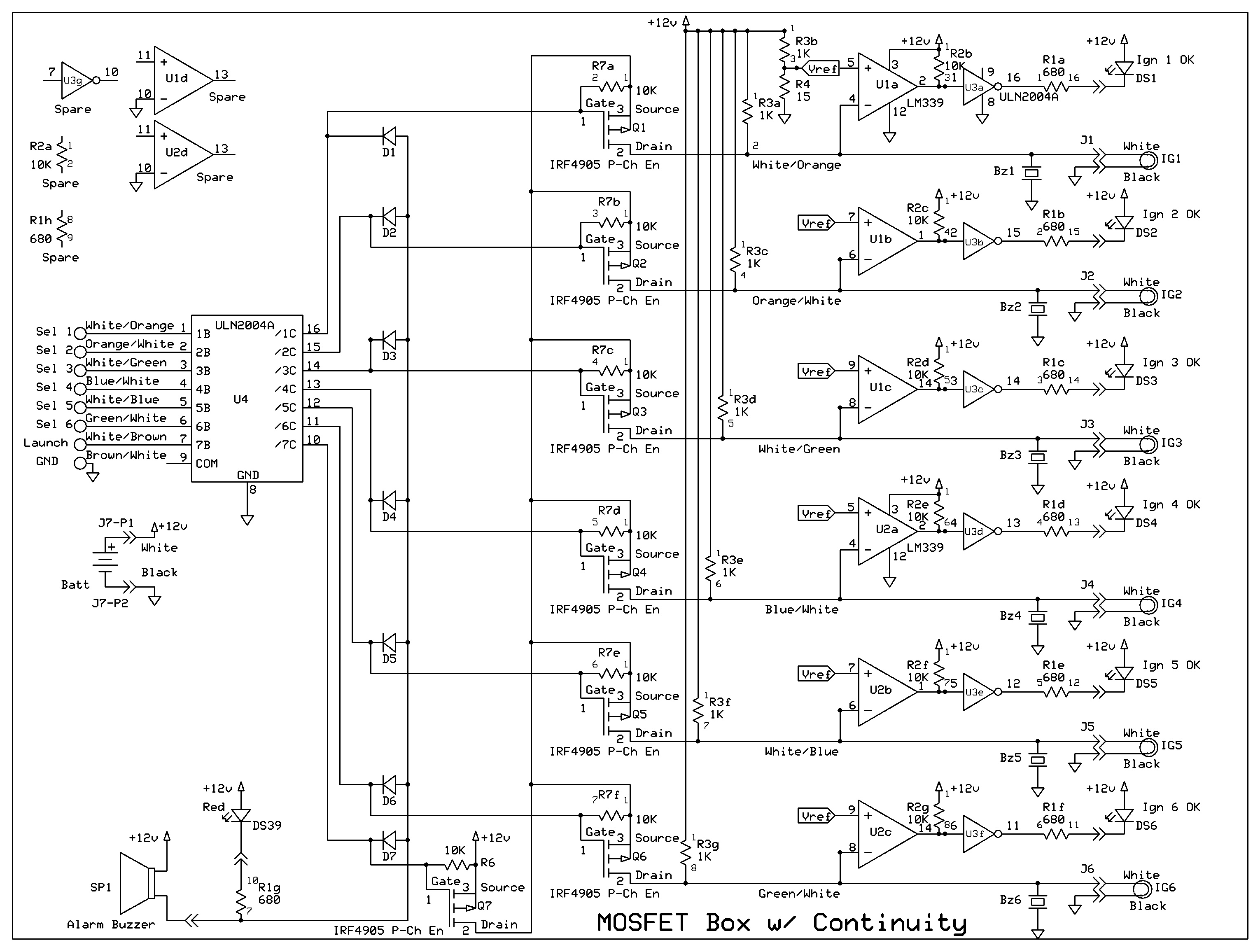
The schematic is 1/2 of the full board. Igniter and continuity circuits are double for a full rack. I'll explain how and why I designed what I have and perhaps you will see a problem. From the left, Sel 1-6 and Launch go high to select the pad for launch and then Launch goes high to launch the rockets on the selected pads. U4 is a ULN2004 darlington array that is very sensitive and allows us to attach 1,000' of wire and still get a signal to the pad. It is inverting with open collectors and requires the pull up resistors R6, and R7a-c. These resistors keep the Q1-3, 7 gates high to keep the MOSFETs off. D1-3, 7 are auctioneering diodes to set off alarm LED and buzzer when danger is present.
The rest is continuity testing for the igniter. Yes there is a problem here too. For instance, when launching pad 1, 12V is applied to the igniter and the series resistors R3a, R3b, and R4. This makes .25W resistors into 1.6W fuses. I'll have to see what I can do about this problem.
The Real Problem: When my MOSFETs are off I am getting a dangerously high (dangerous to rocket motors/humans when connecting rockets) amount of current through the MOSFETs. Q7 drain reads 1.9V and Q1-3 .35V. If I connect an igniter, there is 10-20 mA through the igniter. Close to my 30mA limit, but it works. However, if I put 12V input at Launch pin 7, Q7 appropriately turns on and supplies 12V to the sources of Q1-3. At this point the drains of Q1-3 go to about 3V and if I connect an igniter, I get about 1.5A of current. This is enough to ignite low current igniters before the pad is selected for launch.
I have tested two stand alone MOSFETs (Q7, Q1) out of the circuit and they turn off properly. I have also tested them without the pullup resistors and they act like bistables. If I ground the gate they turn on and if I apply source voltage to the gate, they turn off completely. In fact they have enough capacitance that if I remove all power and power them back up, they remember the last On/Off state and return to being On/Off.
My only guess is that I am dropping too much voltage through the pullup resistor and the MOSFETs are not being completely turned off. I increased the pullup resistors to 1M and they still did not fully turn off.
I also thought about using a U4 different line driver/buffer but I have not found a suitable substitute. I need about 200mA to drive the LED and buzzer and I need high input impedance to work with the 1,000' of Cat5 cable. It is about 1 ohm /10 feet or about 100 ohms for the 1,000' length.
________________________________________________________

Gene Engelgau
Jul 13, 2022, 11:06:50 AM7/13/22
to LunarGeneral google
HI Anthony, First I'm confused by resistor R5 (1K) and then it is supplying multiple 10 ohm resistors to the igniter connection, and the divider R3b, and R4 which sets the comparator threshold. It seems the voltage to the comparator + side is going to vary depending on how many igniters are connected. I would think you would not supply a common resistance via R5, but instead separate these per launch channel so one circuit does not affect the others.
It looks like you using "diode" logic on the gate side of Q1-3 to need to have both the lead selected, AND the launch selected (pulled low out of the darlington). The issue could be the forward turn on of the diode is high enough that the gates of Q1-3 is not pulled up enough to completely turn off the FET. If you use Schottky diodes the Vf is < 0.2V and may work better for your diode logic.
Personally I think it would be simpler to use some NAND devices (or other appropriate boolean devices) to do the logic and control the IRF9Z24 Mosfet gate directly.
Just my quick take on it!
-Gene
- Regards
Gene Engelgau
Web: http://fruitychutes.com - Professional Aerospace Recovery Systems
Web: http://fruitychutes.com - Professional Aerospace Recovery Systems
Facebook: facebook.com/fruitychutes
Twitter: @fruitychutes
Cell: 408-499-9050
--
This list is moderated. Your first port will have to be approved prior to being posted. Feel free to chat about anything your fellow rocketeers would find interesting.
For that latest information be sure to subscribe to LUNAR Announce list at http://lunar.org/docs/lists/lists.shtml#announce
---
You received this message because you are subscribed to the Google Groups "LUNAR General" group.
To unsubscribe from this group and stop receiving emails from it, send an email to lunar-genera...@googlegroups.com.
To view this discussion on the web visit https://groups.google.com/d/msgid/lunar-general/CAM899rNjjSQJ41e_bChmuEoSDnmE7Pfs%3DA%2B_jCFUGAS%3D_VgKaw%40mail.gmail.com.

eric...@gmail.com
Jul 13, 2022, 10:37:56 PM7/13/22
to LUNAR General
Hi Tony,
1) > My only guess is that I am dropping too much voltage through the pullup resistor and the MOSFETs are not being completely turned off. I increased the pullup resistors to 1M and they still did not fully turn off.
Neat design!
1) > My only guess is that I am dropping too much voltage through the pullup resistor and the MOSFETs are not being completely turned off. I increased the pullup resistors to 1M and they still did not fully turn off.
What's the voltage at Q7's gate when Q7 is supposedly "off"? Ideally it should be at or very close to 12V. If you want Q7 to be off more, you may wish to reduce resistor R6 (say to 1K ohm) rather than increase it to 1Mohm. Possibly the same for R7a,R7b, & R7c. At 1K ohm dropping 12v, you'll need a resistor that can take at least 144mW. What's the voltage at Q1-Q3's gates when they are "off"?
2) This probably doesn't matter but what's supposed to keep the voltage at Q7's drain (also Q1-3's source and U3G's input) when Q7 is off? If U3G's input is low, it will output high and back power D1,D2,D3, then R7a, R7b, R7c which will show up on Q7's drain (I'm guessing). You may want to keep the buzzer circuit separate if this is the case, or potentially add in-line series diodes at Q1,Q2,Q3's gates pointing outward away from the base to try to block U3G and D1,D2,D3's power from getting through to R7's. Be aware of the diode's reverse bias voltage as a lot of diodes will back conduct (against the normal flow) if the a high enough voltage like 12v is applied.
Looking forward to the results (and flying again, someday...) Good luck!
Best regards, Eric
eric...@gmail.com
Jul 13, 2022, 11:32:27 PM7/13/22
to LUNAR General
I haven't thought this through but what about just deleting U3G and adding 10K ohm pullups to +12v on each of U4's outputs?
It still seems like there should be a really weak pulldown (10K or larger) on Q7's drain rather than leave it floating.
Just some thoughts. Cheers! - Eric
It still seems like there should be a really weak pulldown (10K or larger) on Q7's drain rather than leave it floating.
Just some thoughts. Cheers! - Eric
Anthony Cooper
Jul 14, 2022, 8:42:11 PM7/14/22
to General LUNAR
First, I wish to thank a few LUNARtics for helping to solve a few problems I encountered in building a new launch control system for LUNAR. Thank you goes out to Les Niles, Steve Kendal, Gene Engelgau and Eric Tang who helpfully pointed out my bad design issues. Linked below is a video I took of the first full scale test to ignite igniters when desired and not to light that when not desired. Watch the 4 minute video if you are curious about the results.
https://youtu.be/Tg0MW2olIX4
https://youtu.be/Tg0MW2olIX4
It should be available to view by 6PM PDT.
________________________________________________________
On Tue, Jul 12, 2022 at 7:33 PM Anthony Cooper <To...@coopers.org> wrote:

srkendal
Jul 14, 2022, 9:05:04 PM7/14/22
to lunar-general
Hi Tony,
Thanks, but I'm pretty sure I was no real help. 🤣
But it does look like you've solved your problems, so congrats on the accomplishments.
However, I really liked the real time igniter test and interesting failures and such. That one crappyhead was so typical! And your comment about using an ematch (plain) as an igniter is spot on. Great for deployment charges, but MUST be supplemented to light a motor.
I would like to see the results (video not really required!) of tests at the full length of cable. I'm thinking that the far away pad is a pretty long piece of wire, and the loss might be significant.
Steve
First, I wish to thank a few LUNARtics for helping to solve a few problems I encountered in building a new launch control system for LUNAR. Thank you goes out to Les Niles, Steve Kendal, Gene Engelgau and Eric Tang who helpfully pointed out my bad design issues. Linked below is a video I took of the first full scale test to ignite igniters when desired and not to light that when not desired. Watch the 4 minute video if you are curious about the results.
https://youtu.be/Tg0MW2olIX4
It should be available to view by 6PM PDT.
________________________________________________________
On Tue, Jul 12, 2022 at 7:33 PM Anthony Cooper <To...@coopers.org> wrote:
--
This list is moderated. Your first port will have to be approved prior to being posted. Feel free to chat about anything your fellow rocketeers would find interesting.
For that latest information be sure to subscribe to LUNAR Announce list at http://lunar.org/docs/lists/lists.shtml#announce
---
You received this message because you are subscribed to the Google Groups "LUNAR General" group.
To unsubscribe from this group and stop receiving emails from it, send an email to lunar-genera...@googlegroups.com.
To view this discussion on the web visit https://groups.google.com/d/msgid/lunar-general/CAM899rO%3Da3WpCY_32AbMj8%2ByXZPureQQXihzooY3tZw2hbEnSA%40mail.gmail.com.
Anthony Cooper
Jul 14, 2022, 9:50:28 PM7/14/22
to General LUNAR
I forgot to include the final schematic.

________________________________________________________
To view this discussion on the web visit https://groups.google.com/d/msgid/lunar-general/6d585531-3f60-4e6f-836c-1ab175556c0a%40edison.

Aleksandar Milivojević
Jul 14, 2022, 11:43:10 PM7/14/22
to lunar-...@googlegroups.com
On Thu, Jul 14, 2022 at 6:05 PM srkendal <srke...@comcast.net> wrote:
However, I really liked the real time igniter test and interesting failures and such. That one crappyhead was so typical! And your comment about using an ematch (plain) as an igniter is spot on. Great for deployment charges, but MUST be supplemented to light a motor.
FWIW, Cesaroni motors use e-matches as igniters. That's why they have that extra pellet in topmost grain. To be more precise, this one in particular https://electricmatch.com/pyrotechnics/see/6/5/mjg-firewire-initiator
It is spec'd to have 300 mA no-fire current, and maximum 40 mA test current. So, whatever is being built, it shouldn't be putting more than 40 mA through it. Because plenty of people will be hooking up those to the launch controller.
srkendal
Jul 14, 2022, 11:54:53 PM7/14/22
to lunar-general
Hi Alexandar!
Yeah, I'd call that "supplemented".
We used to use those pyrodex pellets with standard ematches and they worked great. Plus, with the 30cal pellets, you could just slide them down the ematch, form a little loop around everything with the lead wires, and tuck the matchhead back into the stack. We lit a couple P motors that way. Never failed to work.
Just gotta be mindful of your nozzle throat diameter. It's gotta fit in from the outside, which is why CTI works with a plain ematch. Especially in smaller motors.
-Steve
On Thu, Jul 14, 2022 at 6:05 PM srkendal <srke...@comcast.net> wrote:
However, I really liked the real time igniter test and interesting failures and such. That one crappyhead was so typical! And your comment about using an ematch (plain) as an igniter is spot on. Great for deployment charges, but MUST be supplemented to light a motor.
FWIW, Cesaroni motors use e-matches as igniters. That's why they have that extra pellet in topmost grain. To be more precise, this one in particular https://electricmatch.com/pyrotechnics/see/6/5/mjg-firewire-initiatorIt is spec'd to have 300 mA no-fire current, and maximum 40 mA test current. So, whatever is being built, it shouldn't be putting more than 40 mA through it. Because plenty of people will be hooking up those to the launch controller.
--
This list is moderated. Your first port will have to be approved prior to being posted. Feel free to chat about anything your fellow rocketeers would find interesting.
For that latest information be sure to subscribe to LUNAR Announce list at http://lunar.org/docs/lists/lists.shtml#announce
---
You received this message because you are subscribed to the Google Groups "LUNAR General" group.
To unsubscribe from this group and stop receiving emails from it, send an email to lunar-genera...@googlegroups.com.
To view this discussion on the web visit https://groups.google.com/d/msgid/lunar-general/CAJu5p2fjP4XrSkP0DwB9_%2B26OVBc0dGCT1dG7xMKSw6hrYzirA%40mail.gmail.com.
Anthony Cooper
Jul 15, 2022, 12:43:25 AM7/15/22
to General LUNAR
We are limited to battery voltage divided by 1,000. If the battery was 15V we are limited to 15mA. Below the 40mA test current and way below the 300mA no fire current.
________________________________________________________
--
This list is moderated. Your first port will have to be approved prior to being posted. Feel free to chat about anything your fellow rocketeers would find interesting.
For that latest information be sure to subscribe to LUNAR Announce list at http://lunar.org/docs/lists/lists.shtml#announce
---
You received this message because you are subscribed to the Google Groups "LUNAR General" group.
To unsubscribe from this group and stop receiving emails from it, send an email to lunar-genera...@googlegroups.com.
To view this discussion on the web visit https://groups.google.com/d/msgid/lunar-general/CAJu5p2fjP4XrSkP0DwB9_%2B26OVBc0dGCT1dG7xMKSw6hrYzirA%40mail.gmail.com.
eric...@gmail.com
Jul 15, 2022, 3:14:59 AM7/15/22
to LUNAR General
Hi Tony,
Congrats!!! Nice work! Some minor comments:
- I still wonder about the floating Q7 drain signal and if it might be better to add a 10K+ ohm resistor to GND there.
- +12V on U4 COM seems like a good idea.
- ESD/static electricity is probably not an issue with this circuit. Will it be an issue with some of the more sensitive starters/igniters?
- 1000' of wire will have a bit of inductance to it. It might be interesting to measure any voltage spikes at the igniter end & controller end when the FETs turn on & off, and account for them if needed.
Again, great work and video! Congrats again!!!
Best, Eric
Gene Engelgau
Jul 15, 2022, 10:12:07 AM7/15/22
to LunarGeneral google
Hi Tony, I like it! I see you separated the reference divider and current source resistors for continuity per channel now. Looks like your still using the regular diodes right, no need to change these?
-Gene
- Regards
Gene Engelgau
Web: http://fruitychutes.com - Professional Aerospace Recovery Systems
Web: http://fruitychutes.com - Professional Aerospace Recovery Systems
Facebook: facebook.com/fruitychutes
Twitter: @fruitychutes
Cell: 408-499-9050
To view this discussion on the web visit https://groups.google.com/d/msgid/lunar-general/a401f834-6d7c-429b-b988-a500a7157861n%40googlegroups.com.
Anthony Cooper
Jul 15, 2022, 11:00:31 AM7/15/22
to General LUNAR, eric...@gmail.com
- I still wonder about the floating Q7 drain signal and if it might be better to add a 10K+ ohm resistor to GND there.
- I too have been thinking about that. I used to monitor that point knowing that if voltage was low, we could not launch a rocket. Now it floats to about 6V. I'll look at some options in hopes I can monitor voltage at that point.
- +12V on U4 COM seems like a good idea.
- My understanding of this connection is to dissipate the inductive kick of relays on the output of U4. No relays in this design and no long wires on the output. In our older relay driving system, I do tie that to 12V.
- ESD/static electricity is probably not an issue with this circuit. Will it be an issue with some of the more sensitive starters/igniters?
- Not understanding this one. Static electricity, while high voltage has no current to speak of. Where would the static charge build and dissipate?
- 1000' of wire will have a bit of inductance to it. It might be interesting to measure any voltage spikes at the igniter end & controller end when the FETs turn on & off, and account for them if needed.
- I'm not seeing how the inductive kick of the 1,000' wire gets to the FETs. Perhaps this is the misunderstanding and relates to Steve's comment. These are located at the pad, not at the range head. There is about 15' of 14 gauge wire connected from the FETs to the Igniter in the rocket. The 1,000' of wire only cares the pad select and launch signals to the pads from launch control.
________________________________________________________
To view this discussion on the web visit https://groups.google.com/d/msgid/lunar-general/a401f834-6d7c-429b-b988-a500a7157861n%40googlegroups.com.

Eric Renger
Jul 15, 2022, 3:17:01 PM7/15/22
to lunar-...@googlegroups.com, eric...@gmail.com
I don’t have anything to add to the technical discussion, but i was wondering what the new equipment is for. Is this a new additional launch control system to expand the number of pads? Or is it to replace or repair some of the existing equipment? I know there was a proposal for the club to purchase a brand new commercial wireless launch control system at previous club meetings. Whatever became of that?
Eric
On Jul 15, 2022, at 8:00 AM, Anthony Cooper <To...@coopers.org> wrote:
- I still wonder about the floating Q7 drain signal and if it might be better to add a 10K+ ohm resistor to GND there.
I too have been thinking about that. I used to monitor that point knowing that if voltage was low, we could not launch a rocket. Now it floats to about 6V. I'll look at some options in hopes I can monitor voltage at that point.
- +12V on U4 COM seems like a good idea.
My understanding of this connection is to dissipate the inductive kick of relays on the output of U4. No relays in this design and no long wires on the output. In our older relay driving system, I do tie that to 12V.
- <image.png>
To view this discussion on the web visit https://groups.google.com/d/msgid/lunar-general/CAM899rNvZncUG2N1vmcbO3ueYe7R-bL23DDYY6%2BWmbyGJ3Y1wA%40mail.gmail.com.
Anthony Cooper
Jul 15, 2022, 4:29:38 PM7/15/22
to General LUNAR, eric...@gmail.com
- ... i was wondering what the new equipment is for.
It is intended to replace the circuit boards in the current equipment. We have a reliability problem with the continuity checker where the automotive headlamp relays that we use have high resistance on the back contacts that we use for continuity checks.
- I know there was a proposal for the club to purchase a brand new commercial wireless launch control system at previous club meetings. Whatever became of that?
- Essentially, no follow up. I know nothing about the gear. Cost, setup problems, capacity, etc. No one followed up with details. Our current system I designed and built in 2011. On initial rollout we had a few LED drivers fail and also learned about a distance limitation. It would not reliably communicate past about 300'. Both were fixed. Current problem is the continuity checker reliability and blowing fuses when we use fresh igniter leads. Shinny new alligator clips short out easily and pop fuses until they become corroded.
________________________________________________________
To view this discussion on the web visit https://groups.google.com/d/msgid/lunar-general/D9203D57-CDB7-481D-BF21-EFBD8BB6F38B%40comcast.net.
Eric Renger
Jul 15, 2022, 4:50:20 PM7/15/22
to lunar-...@googlegroups.com, eric...@gmail.com
Sounds good. Do you know if this change will also address the problem of the continuity checks on the newer Aerotech red igniters? The igniters that come with the newer Aerotech single-use EconoJet/EconoMax/Enerjet motors don’t show a continuity light, even when the igniter is fine and hooked up properly. Adding to the problem, those igniters are not very reliable, so sometimes they really are broken internally and do not have continuity. The fact that the continuity light doesn’t work for them makes it impossible to know if you are hooking up a bad igniter.
Eric
To view this discussion on the web visit https://groups.google.com/d/msgid/lunar-general/CAM899rNn_vKyRdOF%3D1X%3DjxwBxmOsz64EG8boOAmwqteQqb41pw%40mail.gmail.com.

Bill Orvis
Jul 15, 2022, 5:00:56 PM7/15/22
to lunar-...@googlegroups.com
So, the MOSFETs you are using are depletion mode? That is, the gate voltage turns off the device.
Bill
--
This list is moderated. Your first port will have to be approved prior to being posted. Feel free to chat about anything your fellow rocketeers would find interesting.
For that latest information be sure to subscribe to LUNAR Announce list at http://lunar.org/docs/lists/lists.shtml#announce
---
You received this message because you are subscribed to the Google Groups "LUNAR General" group.
To unsubscribe from this group and stop receiving emails from it, send an email to lunar-genera...@googlegroups.com.
To view this discussion on the web visit https://groups.google.com/d/msgid/lunar-general/CAM899rNjjSQJ41e_bChmuEoSDnmE7Pfs%3DA%2B_jCFUGAS%3D_VgKaw%40mail.gmail.com.
--
----------------------
William Orvis
226 Joyce St.
Livermore, CA 94550
or...@compuserve.com
---------------------

Cliff Sojourner
Jul 15, 2022, 5:21:12 PM7/15/22
to lunar-...@googlegroups.com
Hi Eric, if you have an ohm meter, can you measure several of these new ones? Or, anyone else have some?
We too have had mixed results with them. Sorry I don't have access to the motor boxes right now and won't for several days.
There are other high resistance, high current igniters (old Quickburst). Tony's system never had trouble with them. But those too are outliers for their resistance and current.
Cliff
Anthony Cooper
Jul 15, 2022, 5:34:17 PM7/15/22
to General LUNAR
- I see you separated the reference divider and current source resistors for continuity per channel now.
- That change makes me nervous. If you measure the voltage at the igniter clips, you get 12V battery voltage. Disconcerting if you are hooking up a motor in a rocket. The resistor does limit the current to Vcc/1K, about 12-15 mA. Safe, but unnerving. In the previous version, I could monitor the voltage at the clips and set off an alarm if needed. I cannot do that with this arrangement.
Next thing that concerns me is that I used to monitor the voltage at Q7 Drain. Set an alarm if voltage was detected. I knew that as long as it was low, you could not launch a rocket. Now, the 12V through R3 pull up resistors and the Q1-6 drains to sources feeds back about 11.3V (with all igniters open, ).

- Looks like you're still using the regular diodes right, no need to change these?
The diodes are 1N4148 general purpose signal diodes. They are rated for 300mA continuous current. They are driving an LED at 20mA and a buzzer at 25mA. Way below their rating. Am I missing something?
________________________________________________________
To view this discussion on the web visit https://groups.google.com/d/msgid/lunar-general/CAO-R2bn_0JH%2B%2BWgFJtoyHqApya9p_MzJYZ4J4D4uQex21O2Jvw%40mail.gmail.com.
Anthony Cooper
Jul 15, 2022, 5:41:19 PM7/15/22
to General LUNAR, eric...@gmail.com
- Do you know if this change will also address the problem of the continuity checks on the newer Aerotech red igniters?
- Any idea what the resistance is for a good igniter? If they are less than 10 ohms, it should not be a problem. That is <10Ω including igniter leads and clips.
Note: I have measured up to 6A to ignite some copperheads. That means total resistance for leads, clips and igniter must be less than 2Ω to get 6A through the igniter.
________________________________________________________
To view this discussion on the web visit https://groups.google.com/d/msgid/lunar-general/11678496-EFBB-4570-948D-013B7AE4CE83%40comcast.net.
Aleksandar Milivojević
Jul 15, 2022, 5:45:05 PM7/15/22
to lunar-...@googlegroups.com
I measured them a few years ago, see https://groups.google.com/g/lunar-general/c/9FtErNI42A8/m/mIG9e7mgBgAJ
21 ohms for the new FirstFire Micro igniters (Quest branded), compared to only 6 for the older FirstFire Mini igniters (AeroTech branded). This was on a sample of one box of each.
To view this discussion on the web visit https://groups.google.com/d/msgid/lunar-general/2AB18FA6-9307-4E0E-B6EE-0BDF9EC6DDAD%40employees.org.
Anthony Cooper
Jul 15, 2022, 5:46:14 PM7/15/22
to General LUNAR
- So, the MOSFETs you are using are depletion mode? That is, the gate voltage turns off the device.
- They are P-Channel Enhancement mode MOSFETs (IRF9Z24 P-Channel Enhancement 11A and IRF4905 P-Channel Enhancement 74A MOSFETs). Gate-Source voltage must be greater than or equal to zero to keep them off. That is the reason for the 10K Gate-Source resistors. When the gate gets pulled down, the MOSFET turns on.
________________________________________________________
To view this discussion on the web visit https://groups.google.com/d/msgid/lunar-general/23dc6bb6-a962-5d70-a1fd-58ea7baf3a0e%40comcast.net.
Anthony Cooper
Jul 15, 2022, 6:05:12 PM7/15/22
to General LUNAR
Now some disturbing news. When I started working on this project this morning, measurements were off. I found two MOSFETs shorted Source to Drain (Q7 & Q2) and Q1 that was about 750Ω. I replaced it and the new one measured about 900Ω. I swear I measured it before I installed it and it was open. I replaced it a second time and now everything is back to normal. After this incident, I am going to build a complete test rig in a stand alone box and carefully testing it during a few launches under tight supervision.
________________________________________________________
Bill Orvis
Jul 15, 2022, 6:15:54 PM7/15/22
to lunar-...@googlegroups.com, Anthony Cooper
So, What was the problem with your original circuit?
Bill
--
This list is moderated. Your first port will have to be approved prior to being posted. Feel free to chat about anything your fellow rocketeers would find interesting.
For that latest information be sure to subscribe to LUNAR Announce list at http://lunar.org/docs/lists/lists.shtml#announce
---
You received this message because you are subscribed to the Google Groups "LUNAR General" group.
To unsubscribe from this group and stop receiving emails from it, send an email to lunar-genera...@googlegroups.com.
To view this discussion on the web visit https://groups.google.com/d/msgid/lunar-general/CAM899rO%3Da3WpCY_32AbMj8%2ByXZPureQQXihzooY3tZw2hbEnSA%40mail.gmail.com.
Cliff Sojourner
Jul 15, 2022, 6:57:01 PM7/15/22
to lunar-...@googlegroups.com
Tony, many stories going around about counterfeit parts. Lots of work to test everything before using, but probably worthwhile overall.
Cliff
Cliff
Cliff Sojourner
Jul 15, 2022, 6:57:46 PM7/15/22
to lunar-...@googlegroups.com
Thanks! There ya go, Tony.
Gene Engelgau
Jul 16, 2022, 9:31:33 AM7/16/22
to LunarGeneral google
Here is the data sheet:
So the gate to source threshold voltage (Vgs) is -2 to -4 volts depending on the specific device. A Vgs below this is considered "off". So you don't need 0 volts to have the device completely off, but a lower gate to source voltage is better to assure minimal leakage.
-Gene
- Regards
Gene Engelgau
Web: http://fruitychutes.com - Professional Aerospace Recovery Systems
Web: http://fruitychutes.com - Professional Aerospace Recovery Systems
Facebook: facebook.com/fruitychutes
Twitter: @fruitychutes
Cell: 408-499-9050
To view this discussion on the web visit https://groups.google.com/d/msgid/lunar-general/44697087-4003-41A8-96D4-5795BD3D89C5%40employees.org.
Eric Renger
Jul 16, 2022, 6:25:59 PM7/16/22
to lunar-...@googlegroups.com
Thanks, Aleksandar.
To view this discussion on the web visit https://groups.google.com/d/msgid/lunar-general/CAJu5p2eeHPeAzcQpoKr%2BzHdzpqq0Wc-bqZJ_5WFDmaa%3Dy%3DZP4A%40mail.gmail.com.
Eric Renger
Jul 16, 2022, 7:18:43 PM7/16/22
to lunar-...@googlegroups.com
Tony,
As Aleksandar mentioned, the new FirstFire Minis measure 21 ohms for a good igniter. So that’s greater than 10 ohms and would not show continuity, correct?
These are the igniters now shipping with the Quest branded 18mm and 24mm motors and Aerotech single-use motors with the sub-brand names like Econojet, EconoMax, Enerjet, etc — E20, F44, F20, F23, F27, F42, F67, G74 and others. They are nice and affordable motors, but the igniters are a problem with the LUNAR launch system because of lack of a continuity check. What makes it worse is that the igniters also are not as reliable as the older ones and are sometimes legitimately bad, so a continuity check is extra important for these. I always have my doubts when using these at LUNAR.
Eric
To view this discussion on the web visit https://groups.google.com/d/msgid/lunar-general/CAM899rPoh2cJtYE%2BM84%3Dx-hnHt63JQwe8_WdXODbtENVO6UV%2Bw%40mail.gmail.com.
Anthony Cooper
Jul 16, 2022, 7:47:49 PM7/16/22
to General LUNAR
- The new FirstFire Minis measure 21 ohms for a good igniter. So that’s greater than 10 ohms and would not show continuity, correct?
- Correct and at 21 ohms there would only be about 500mA of current. I'm skeptical that it will light the igniter.
- What makes it worse is that the igniters also are not as reliable as the older ones and are sometimes legitimately bad, so a continuity check is extra important for these. I always have my doubts when using these at LUNAR.
- Does Anyone know how much current it takes to light a FirstFire Mini? I think I am about to make a new video. Anyone near me happen to have a FirstFire Mini that they would donate to science?
________________________________________________________
To view this discussion on the web visit https://groups.google.com/d/msgid/lunar-general/6C30E5E3-0C33-4D85-A8BD-50441F952957%40comcast.net.
Anthony Cooper
Jul 16, 2022, 7:57:52 PM7/16/22
to Bill Orvis, General LUNAR
Not entirely sure. I did find one trace that was too close to another trace and they shorted together. I suspect I may have had MOSFETs from the start. I did get some great suggestions including how to solve the continuity test from burning up a 10 ohm resistor.
eric...@gmail.com
Jul 18, 2022, 2:20:20 PM7/18/22
to LUNAR General
Hi Tony,
- +12V on U4 COM seems like a good idea.
- My understanding of this connection is to dissipate the inductive kick of relays on the output of U4. No relays in this design and no long wires on the output. In our older relay driving system, I do tie that to 12V.
That's correct that it isn't needed. It looks like it won't do anything in this circuit unless +12V on COM reverse biases that diode and puts out a voltage on the output.
- ESD/static electricity is probably not an issue with this circuit. Will it be an issue with some of the more sensitive starters/igniters?
- Not understanding this one. Static electricity, while high voltage has no current to speak of. Where would the static charge build and dissipate?
Just wondering if electrostatic discharge will affect the more sensitive igniters. While walking around, we can build up & be at a different potential than the launcher system, and touching the GND lead will equalize the potential (much like getting zapped touching your car when you get out of it). Just wondering if that would set anything off.
- 1000' of wire will have a bit of inductance to it. It might be interesting to measure any voltage spikes at the igniter end & controller end when the FETs turn on & off, and account for them if needed.
- I'm not seeing how the inductive kick of the 1,000' wire gets to the FETs. Perhaps this is the misunderstanding and relates to Steve's comment. These are located at the pad, not at the range head. There is about 15' of 14 gauge wire connected from the FETs to the Igniter in the rocket. The 1,000' of wire only cares the pad select and launch signals to the pads from launch control.
Oh. If it's only the control signals and not the main load, that's certainly much better and not a concern. Thanks for the clarification.
So what's the launch system look like now? - Eric :)
Anthony Cooper
Jul 19, 2022, 10:50:27 AM7/19/22
to General LUNAR
I started building a box to put the system in and then it will be ready for some testing. Since I found two MOSFETs shorted, I'm really nervous about safety. I came up with a way to ensure that the rocketeer is safe and I will reveal that when I complete building the system. I discussed it with Bill Orvis and he agrees that it is a simple but genius idea. If it works well, expect a Sport Rocketry technical submission and a personal recommendation that all launch systems incorporate this idea. I'm away for a week visiting my sister. When I return, I'll be hot on the build and don't expect it to take more than a week to complete.
Still need a First Fire mini to test resistance and current draw if someone has one to sacrifice.
________________________________________________________
--
This list is moderated. Your first port will have to be approved prior to being posted. Feel free to chat about anything your fellow rocketeers would find interesting.
For that latest information be sure to subscribe to LUNAR Announce list at http://lunar.org/docs/lists/lists.shtml#announce
---
You received this message because you are subscribed to the Google Groups "LUNAR General" group.
To unsubscribe from this group and stop receiving emails from it, send an email to lunar-genera...@googlegroups.com.
To view this discussion on the web visit https://groups.google.com/d/msgid/lunar-general/9a8c193b-5cfd-4b64-9fde-9ec7c2a9555en%40googlegroups.com.
Anthony Cooper
Jul 26, 2022, 12:25:32 PM7/26/22
to General LUNAR
I bought 18 FirstFire Micro Igniters. I guess there are minis and micros. I did not find minis available. Micro instructions specify that you must use at least six volts and 2 amps to ignite these igniters. This implies that they are about 3Ω. My measurements showed that they ranged from 1.5Ω to 8.6Ω. (1.5,
3.2, 3.6, 3.9, 4.0, 4.1, 4.1, 4.1, 4.1, 4.6, 5.2, 5.5, 5.5, 6.0, 7.0, 7.1, 7.5,
8.6). My lead resistance was about .5Ω. Other igniters were Copperhead - .4Ω, Estes - .8Ω, J-Tek - 1.3Ω, First Fire - 4.6Ω, Tiger Tail - 7.8Ω.
Anthony M. Cooper
31120 Chicoine Ave.
Hayward, CA 94544-7432
31120 Chicoine Ave.
Hayward, CA 94544-7432

Doug Wade
Jul 26, 2022, 2:08:30 PM7/26/22
to lunar-...@googlegroups.com
While we’re on the topic Frankum igniters are pretty popular and I’ve seen them not show continuity at LUNAR even though they do everywhere else.
Perhaps he’ll send you a grab bag or at least get you the specs.
--
This list is moderated. Your first port will have to be approved prior to being posted. Feel free to chat about anything your fellow rocketeers would find interesting.
For that latest information be sure to subscribe to LUNAR Announce list at http://lunar.org/docs/lists/lists.shtml#announce
---
You received this message because you are subscribed to the Google Groups "LUNAR General" group.
To unsubscribe from this group and stop receiving emails from it, send an email to lunar-genera...@googlegroups.com.
To view this discussion on the web visit https://groups.google.com/d/msgid/lunar-general/CAM899rOrSOYMhwgXQ3Zbu1yxy-AVe6Qk4NXtiG_g%3DC86Vm-4Lg%40mail.gmail.com.
Anthony Cooper
Jul 27, 2022, 12:39:45 AM7/27/22
to General LUNAR
Got to love their specifications. Requires 12V.
________________________________________________________
Anthony M. Cooper
31120 Chicoine Ave.
Hayward, CA 94544-7432
31120 Chicoine Ave.
Hayward, CA 94544-7432
VP and Membership for lunar.org
To view this discussion on the web visit https://groups.google.com/d/msgid/lunar-general/04223406-26E6-45B2-A4D8-C500C9D43F14%40eljay.org.

William Kellermann
Jul 27, 2022, 10:54:24 AM7/27/22
to lunar-...@googlegroups.com
I’m sure he’d love tested specs to publish…
His HP pads look pretty cool.
William Kellermann
On Jul 26, 2022, at 9:39 PM, Anthony Cooper <To...@coopers.org> wrote:
To view this discussion on the web visit https://groups.google.com/d/msgid/lunar-general/CAM899rOmHgfd66fTtnGD4zLF9fEkcM9AGS-6n-VBz1t2fUc91Q%40mail.gmail.com.
Anthony Cooper
Jul 28, 2022, 1:30:01 PM7/28/22
to General LUNAR
I wrote him. He offered up specs for a specific igniter. I wrote him back and asked him for specs for all of them and explain why it was after them.
______________________________________
Anthony M. Cooper
31120 Chicoine Ave.
Hayward, CA 94544-7432
VP and Membership for lunar.org
Membership for mgscv.org
Cell: 510-589-5292
Anthony M. Cooper
31120 Chicoine Ave.
Hayward, CA 94544-7432
VP and Membership for lunar.org
Membership for mgscv.org
Cell: 510-589-5292
To view this discussion on the web visit https://groups.google.com/d/msgid/lunar-general/F2CC0F37-9C3D-49DC-9803-3AB9D8EF014F%40comcast.net.
Anthony Cooper
Aug 10, 2022, 4:21:10 PM8/10/22
to General LUNAR
I'm back again. I got a complete box built for testing. MOSFET Launcher Test Video https://photos.app.goo.gl/TUp3fZb9caDaU1gz6
When I finished it today, I found one MOSFET that was leaking about 15mA source to drain. That was a total of 30mA going through the continuity check circuit and that is too much. Having anticipated issues like this, I came up with the idea of building a buzzer and putting it inside the 120VAC connector. The idea is for the alarm to go off if there is enough current to light an igniter. Problem is that these buzzers are far more sensitive and make noise at a lower current than I expected. I tested them at:
0.75Vdc 0.3mA Starts making noise
1.00Vdc 2.0mA Easily audible
5.00Vdc 25mA Loud
1.00Vdc 2.0mA Easily audible
5.00Vdc 25mA Loud
At continuity check current of 15mA, sometimes they make a low noise. I think it will be so subtle that no one will notice, but I do not want people to ignore the noise when they have too much current available. Any thoughts on how to make a noise maker that will not start making noise until after about 15mA of available current without taking the current and falsely tripping the continuity circuit?
________________________________________________________
eric...@gmail.com
Aug 16, 2022, 5:32:27 PM8/16/22
to LUNAR General
Haven't thought about this but if you were to Rube Goldberg it, you could use a Texas Instruments INA301 current sense amp (at 20x, 50x, or 100x voltage multiplier), measuring an appropriately small resistance (0.001-0.01 ohm) and use the output to enable the speaker. If the resistor is in-line with the igniter, it will need to handle the power of the being dumped across it. Again, just a quick thought.
It seems like there should be a simpler solution... - Eric
Reply all
Reply to author
Forward
0 new messages