Attempting to manually replace Sample Clock in triggered acquisition
493 views
Skip to first unread message

Connor Roncaioli
Jun 2, 2021, 4:39:10 PM6/2/21
to the labscript suite
Good Afternoon All,
I'm working on a measurement where I'm trying to sample an analog input from a photodetector onto a USB-6363 NI DAQ card. The input needs to be precisely timed relative to a pulse train of instructions from a Pulse Blaster (down to hundreds, or ideally tens of nanoseconds). Originally measurements were taken by instructing the NI DAQ to acquire at a given time using the acquire() function for an AnalogIn device as described in line 1732 of labscript.py, for a single data point every time (corresponding to a 1 microsecond acquisition window)
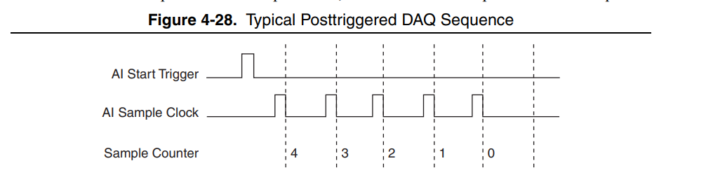
Unfortunately, the PB and NI DAQ have a mutual clock-drift of about 150ppm. As a result the sample clock in the NI DAQ would slew by about 1 microsecond over the course of a large number of measurements. As best I understand it the AI Start Trigger was being triggered by the PB (at the appropriate window) but the AI Sample Clock of the NI DAQ was moving around, causing a 1 microsecond drift that cannot be accurately compensated. (as described in page 4-45 of the NI DAQ X series manual)
Where /NI1/PFI2 is the channel to which I am sending digital pulses (1 microsecond long). Unfortunately I get the "No data was acquired. Perhaps the acquisition task was not triggered to start, is the device connected to a pseudoclock?" error which indicates that the acquisition did not properly resolve. (The NI DAQ card then needs to be manually rebooted in blacs) If I attempt the same acquisition with the original Sample Clock code the acquisition completes normally, indicating that this is the source of the problem.
So far I've attempted sending a single 1-microsecond ttl pulse through /NI1/PFI2 at variable delay, as well as a "500KHz-like" pulse train of on-1us off-1us on-1us [...] pulses.
An example experiment would look something like the following:
start()
t = 0
t+=1
analogOne.acquire( 'output_file_name', start_time = t, end_time = t+1e-2)
t+= 1e-5
for dummyVal in np.arange(0,1001):
t+= 1e-6
Misc_ttl.go_high(t)
t+= 1e-6
Misc_ttl.go_low(t)
t += 0.1
#program stop
stop(t + 1e-3)
I'm working on a measurement where I'm trying to sample an analog input from a photodetector onto a USB-6363 NI DAQ card. The input needs to be precisely timed relative to a pulse train of instructions from a Pulse Blaster (down to hundreds, or ideally tens of nanoseconds). Originally measurements were taken by instructing the NI DAQ to acquire at a given time using the acquire() function for an AnalogIn device as described in line 1732 of labscript.py, for a single data point every time (corresponding to a 1 microsecond acquisition window)
Unfortunately, the PB and NI DAQ have a mutual clock-drift of about 150ppm. As a result the sample clock in the NI DAQ would slew by about 1 microsecond over the course of a large number of measurements. As best I understand it the AI Start Trigger was being triggered by the PB (at the appropriate window) but the AI Sample Clock of the NI DAQ was moving around, causing a 1 microsecond drift that cannot be accurately compensated. (as described in page 4-45 of the NI DAQ X series manual)
To correct this I'm attempting to replace the AI sample clock of the NI DAQ with a series of pulses I have direct control over from an additional PB digital out channel. I've done this by replacing line 488 of NI_DAQmx\blacs_workers.py:
self.task.CfgSampClkTiming(
"", rate, DAQmx_Val_Rising, DAQmx_Val_ContSamps, num_samples
)
with:
self.task.CfgSampClkTiming(
'/NI1/PFI2', rate, DAQmx_Val_Rising, DAQmx_Val_ContSamps, num_samples
)
Where /NI1/PFI2 is the channel to which I am sending digital pulses (1 microsecond long). Unfortunately I get the "No data was acquired. Perhaps the acquisition task was not triggered to start, is the device connected to a pseudoclock?" error which indicates that the acquisition did not properly resolve. (The NI DAQ card then needs to be manually rebooted in blacs) If I attempt the same acquisition with the original Sample Clock code the acquisition completes normally, indicating that this is the source of the problem.
So far I've attempted sending a single 1-microsecond ttl pulse through /NI1/PFI2 at variable delay, as well as a "500KHz-like" pulse train of on-1us off-1us on-1us [...] pulses.
An example experiment would look something like the following:
start()
t = 0
t+=1
analogOne.acquire( 'output_file_name', start_time = t, end_time = t+1e-2)
t+= 1e-5
for dummyVal in np.arange(0,1001):
t+= 1e-6
Misc_ttl.go_high(t)
t+= 1e-6
Misc_ttl.go_low(t)
t += 0.1
#program stop
stop(t + 1e-3)
the above would be an example of a pulse train, where Misc_ttl is the digital output of the PB sending a signal to /NI1/PFI2, and analogOne is the analog input channel which should be triggered by the PB clock signal.
Thanks in advance for any insight provided.
-Connor Roncaioli
Thanks in advance for any insight provided.
-Connor Roncaioli

dihm....@gmail.com
Jun 3, 2021, 3:58:04 PM6/3/21
to the labscript suite
This may not actually be helpful, but sometimes PFI lines are dedicated to specific functions (that are not amazingly documented) that prevent you from using them as you would expect of a "general purpose input terminal." An example of this is in the wait monitor, where digital edges to be counted by the internal ctr0 have to be on PFI9 (for most DAQs). You may want to try other PFI lines or even directly connecting to a digital I/O line (via 'portx/liney' syntax) that isn't associated with a PFI at all.
-David
Connor Roncaioli
Jun 3, 2021, 4:19:59 PM6/3/21
to the labscript suite
Hi David, thanks for the response.
I've managed to make a small amount of (somewhat blind) progress. By changing the PFI line reference from
I've managed to make a small amount of (somewhat blind) progress. By changing the PFI line reference from
self.task.CfgSampClkTiming(
'/NI1/PFI2', rate, DAQmx_Val_Rising, DAQmx_Val_ContSamps, num_samples
)
to
self.task.CfgSampClkTiming(
'PFI2', rate, DAQmx_Val_Rising, DAQmx_Val_ContSamps, 1
)
I was able to (partially) circumvent the error I was seeing before. Now blacs will no longer throw the specific "no data was acquired[...]" error, but the .h5 traces which should hold the data from the run are now length 0 (i.e. empty). If I disable the pulses going in to PFI2 I recover the "no data was acquired[...]" error, so the NI DAQ is sensitive for one reason or another to pulses on the PFI2 line. Also note, the num_samples value had to be changed to some much smaller number since if this value was larger than the number of pulses I could provide during the acquisition window (which it is, due to the PB having a maximum of about 4k instructions, and num_samples = 1e4) I get the "no data was acquired[...]" error as well (I believe this is because not enough triggers were collected compared to what was requested in memory?)
At this point I'm trying to better understand
At this point I'm trying to better understand
self.task.RegisterEveryNSamplesEvent(
# DAQmx_Val_Acquired_Into_Buffer, num_samples, 0, self.task.callback_ptr, 100
)
on line 496 of blacs_workers.py since this seems to handle the task of recovering data collected from the NI DAQ (unfortunately a process I don't well understand) - and data recovery at least seems to be part of the issue here...
-Connor
-Connor
Connor Roncaioli
Jun 3, 2021, 4:21:41 PM6/3/21
to the labscript suite
Quick clarification, the line is:
self.task.RegisterEveryNSamplesEvent(
DAQmx_Val_Acquired_Into_Buffer, num_samples, 0, self.task.callback_ptr, 100
)

Zak V
Jun 3, 2021, 5:49:05 PM6/3/21
to the labscript suite
Hi Connor,
Unfortunately I'm not at all familiar with analog input in DAQmx so I can't help you much there. For the limit on the number of pulseblaster instructions though you may be able to work around that using the repeat_pulse_sequence() method (here in the current version of labscript at the time of this writing). I haven't used that method personally, but generally using a for loop with a separate labscript command makes new pseudoclock instructions for each iteration of the loop. However, using the built-in functions lets labscript be a bit smarter about generating the instructions. David knows much more about pseduoclocks than I do (so feel free to correct me if I'm wrong), but my understanding is that using a for loop generates instructions like "go high 1us, go low 1us, go high 1us, go low 1us..." leading to many instructions. On the other hand repeat_pulse_sequence() generates instructions more like `go high 1us, go low 1us, repeat the last two steps 1000 times`. The former leads to thousands of instructions for thousands of iterations, while the latter is only a few instructions regardless of the number of iterations. This same idea applies to analog outputs as well, which is why it's better to create a ramp using the ramp() method instead of manually creating a ramp by setting the output to a new value with constant() repeatedly in a for loop.
Sorry I'm no help on the DAQmx side, but hopefully this helps you acquire longer waveforms once you get those issues resolved.
Cheers,
Zak

Philip Starkey
Jun 5, 2021, 7:05:05 AM6/5/21
to labscri...@googlegroups.com
Hi Connor,
Zak's suggestion is a good one as your issue is almost certainly caused (or made worse) by not being able to generate enough pulses. Our NI card device code is designed to acquire constantly during a shot and then chuck up later into the requested acquisitions. So it is going to need a constant clock for the whole experiment (unless you want to redesign the acquisition code).
You might also want to consider just using a function generator to generate the pulses constantly (if you have access to one). Most function generators can be externally referenced. Depending on whether your PulseBlasters are externally referenced, this would either mean feeding in that external reference to the function generator too, or if not, I believe most PulseBlasters also generate a reference output that can be fed to other devices.
Once you have that working, you might find it easier to transition to generating the pulses a different way if you don't want to tie up the function generator permanently.
Cheers,
Phil
Connor Roncaioli
Jun 8, 2021, 3:35:03 PM6/8/21
to the labscript suite
Hi all,
I'm still working on this problem - I may indeed switch to disciplining both the pulseblaster and NI DAQ, but I'm working through the available options first - I'll update when more progress is made!
Zak I am trying to make use of the repeat_pulse_sequence() method you've described. Unfortunately I get the error "digital output MW_ttl is on clockline that does not support ramping. It cannot have a function ramp as an instruction.". It seems like this method is for feeding analog outputs a ramping value (whereas I'm trying to give repeat go_high() go_low() instructions to a DO line). Is there a similar functionality for digital outs?
Thanks,
Connor R
dihm....@gmail.com
Jun 8, 2021, 4:12:13 PM6/8/21
to the labscript suite
Connor,
I think I may understand the issue you are butting into right now.
This function
self.task.CfgSampClkTiming(
'PFI2', rate, DAQmx_Val_Rising, DAQmx_Val_ContSamps, 1
)
configures your analog input task to look for its sample clock on PFI2 with a rate of `rate`. It also configures the analog inputs to continuously sample once the task is started, and the `num_samples` parameter, when doing continuous samples, sets the size of the memory buffer. This isn't working as you would hope for at least two reasons I can see:
First, this function tells the DAQ where to find its sample clock, not the start trigger. As configured, your analog inputs will only sample when a PB pulse comes in on PFI2 (so 1 sample every 2us).
Second, the acquisition is configured to start once and continuously sample (at the times set by the PFI2 input) until the task is ended. That isn't really what you are intending, where you would like to start_trigger an acquisition (a finite number of samples at rate x) every 2 us. As far as I know, that requires a fairly different style of analog acquisition known as a retriggerable task (took a fair bit of googling to figure out the keywords for that, NI documentation can be such garbage some times). If you are tweaking the labscript DAQ class anyway, that may not be too difficult to implement, but it's pretty far from how labscript does things now. Providing a common clock is basically the opposite extreme of involved hardware modifications but no changes to the software required.
As for the repeat_pulse_sequence, that doesn't really surprise me. I believe that is a helper function for generating ramps on a clockline, but the direct digital outputs of the pulseblaster are treated differently, as far as labscript is concerned. If you were enterprising, the new PrawnBlaster device has significantly more allowed instructions and internally it could squash down your for loop of commands into a single repeating instruction anyway.
Regardless, there are still quite a few options that will work, though it does seem like none of them are especially trivial.
-David
Connor Roncaioli
Jun 8, 2021, 4:39:25 PM6/8/21
to the labscript suite
Hi David, thanks for the reply!
"First, this function tells the DAQ where to find its sample clock, not the start trigger. As configured, your analog inputs will only sample when a PB pulse comes in on PFI2 (so 1 sample every 2us).
Second, the acquisition is configured to start once and continuously sample (at the times set by the PFI2 input) until the task is ended."
This actually describes the behavior I'm aiming for quite well. The ideal case would be I set an acquisition to begin in some window, and then send a single pulse on the sample clock (corresponding to one sample taken at a precise point) corresponding to one data point of interest. The 500kHz pulses I'm sending in right now are a test-case (1 sample every 2us) but aren't the end-goal. We've written a method that allows us to call acquire() onto a single 'output_file_name' several times in a way that re-opens and writes data to that trace sequentially, so calling this method in several runs would allow us to have precise control over when the sample is collected (by providing a single rising edge on the sample clock per call of the acquire() function)
-Connor R
-Connor R
Connor Roncaioli
Jun 8, 2021, 4:46:47 PM6/8/21
to the labscript suite
Sorry to split this into two replies:
Would it be possible to write a method similar to the repeat_pulse_sequence which does something similar for digital outs? I'd be willing to give it a shot, but I don't really know what exactly is required to bypass the 4k instruction limitation for the pulse blaster (if indeed this is possible using a helper function)
-Connor R
Zak V
Jun 8, 2021, 6:06:29 PM6/8/21
to the labscript suite
Hi Connor,
I think that the text in the "digital output MW_ttl is on clockline that does not support ramping..." error is a bit misleading in this situation. I believe it's written assuming that it came up because you tried to ramp an analog channel which doesn't support ramps, but the same error occurs in this different situation as well. `repeat_pulse_sequence()` is designed for digital outputs (it's a method of the `labscript.DigitalQuantity` class); it's is written to output sequences of HIGH/LOW on a digital channel. From David's email, it sounds like it's used to make the waveforms for clock lines, but it should be possible to use it for digital outputs as well.
The error you saw occurs because the pulseblaster direct outputs are configured as if they were on a slow clock line that doesn't support ramps, which is set here. It's not clear to me why that `ClockLine` is created with `ramping_allowed=False`. In a hacky test I overwrote that setting by adding `Misc_ttl.parent_clock_line.ramping_allowed = True` to a labcript sequence right before calling `repeat_pulse_sequence()`, which worked fine. It's possible that the pulseblaster direct outputs were configured with `ramping_allowed=False` because whoever wrote it was thinking that you can't do analog ramps with digital outputs, but they didn't consider that setting `ramping_allowed=False` would prohibit using `repeat_pulse_sequence()`. Maybe someone more knowledgeable about this could comment? It could be that there is another reason for setting `ramping_allowed=False`.
In the mean time, hopefully you can keep making progress using that hack or using Phil's suggestion of using a physical function generator.
Cheers,
Zak
Connor Roncaioli
Jun 9, 2021, 6:14:58 AM6/9/21
to the labscript suite
Very useful! Thanks!

Connor Roncaioli
Jun 10, 2021, 3:43:21 PM6/10/21
to the labscript suite
Afternoon All,
Zak I was able to get the repeat_pulse_sequence() function working on the pulse blaster! It did, however, require that at 'time zero' of a given pulse train period that the associated channel has some instruction, otherwise there is an unhandled error. Now I have a (different) error creeping in where using the repeat_pulse_sequence() instruction causes no compilation error, but when the shot is run it only does part of the actual pulse train (and indeed, it seems like other instructions won't get passed to their associated equipment either). I hooked up a repeating pulse sequence to an oscilloscope and no matter which variables I change the pulse duration terminates at 300us after the pulse train begins (even though the total pulse duration is set to 10ms, or more). I've tried changing several things including making the pulse period longer by including longer spaces between pulses, arbitrarily increasing the duration value in repeat_pulse_sequence(duration = [float]) by factors of 10 etc. 300us after calling repeat_pulse_sequence() the states of the PulseBlaster & NI DAQ card stop changing. - Do you have any experience with this type of error?
Thanks again,
-Connor R
Zak V
Jun 10, 2021, 7:45:33 PM6/10/21
to the labscript suite
Hi Connor,
I've never actually used `repeat_pulse_sequence()` before testing it for this email thread, so I don't have prior experience with that issue. That said, when I compile a shot which uses `repeat_pulse_sequence()` on a pulseblaster output and open it in runviewer, I can see the same behavior you mentioned where the pulse train doesn't repeat. Interestingly `repeat_pulse_sequence()` seems to work as I would expect when I use it on an NI card's digital output.
This makes me suspect that there may be a bug in the pulseblaster or pseudoclock code for generating the instructions that are saved to the hdf5 file. That or there's a different reason why the pulseblaster direct output clockline is created with `ramping_allowed=False`, and we're seeing what goes wrong if that setting is changed. I'd suggest digging into the `PulseBlaster.generate_code()` method in labscript device's `PulseBlaster.py` to understand how the pulseblaster instructions are generated and why they aren't coming out as desired in this situation. You can see the compiled output instructions by opening a shot's hdf5 file with hdfView, then navigating to devices->(pulse blaster name)->PULSE_PROGRAM, selecting the "General Object Info" tab, and finally clicking "Show Data with Options". There the "flags" column shows which outputs are off/on, then "inst" specifies the pulseblaster instruction code, "inst_data" specifies any arguments for the instruction, and "duration" is the duration of that output. For more details, see the pulseblaster manuals.
If you do figure something out, I'd suggest opening an issue on the github (https://github.com/labscript-suite/labscript-devices/issues) so we can really get into the details without worrying about spamming people's inboxes. Feel free to tag me with my github username (zakv) in the issue.
Cheers,
Zak
Philip Starkey
Jun 10, 2021, 8:49:08 PM6/10/21
to labscri...@googlegroups.com
Hi All,
Apologies I haven't been able to engage with this discussion again sooner. I don't believe it's possible to set ramping_allowed=True for the PulseBlaster direct outputs. The PulseBlaster instruction generation code does not know how to unwrap that appropriately, nor would it be trivial to merge that instruction set with those from other clocklines on the PulseBlaster.
There is a hack that will do what you want, but I need to stress it will only work if you don't use any of the other PulseBlaster outputs at the same time as your pulse sequence (I think you have 2 PulseBlasters though so you should be OK if you make sure your second PulseBlaster is only doing this). Ultimately, you may find it cost effective to transfer the following scheme to a PrawnBlaster (since it has 4 independent pseudoclocks that only have one clockline each, so there is no risk of accidentally using another output). However, the PrawnBlaster would almost certainly need to be externally referenced to a common lab reference source as I doubt the onboard oscillator is anywhere near as stable as the PulseBlasters.
The way to achieve a repeated pulse sequence on a PulseBlaster direct output is to trick it into thinking it is clocking a device like an NI card. You can do this by creating a ClockLine on a PulseBlaster output, attaching a DummyIntermediateDevice to the ClockLine, and then a single AnalogOut to the DummyIntermediateDevice (I believe any port/connection is valid). Then you command output on the analog output in a way that generates the pseudoclock signal that matches the pulse train you want. For example, doing a linear ramp with a sample rate of 500 KHz should generate a pulse every 2us. You will probably want to verify this in runviewer (look at the ClockLine trace), particularly around the final points.
If you do accidentally command output on another PulseBlaster output (clock line or directout output) while using the above "hack" this may cause jitter in the pulse timing and/or result in an increase in the pulse frequency (as all clock lines tick at the fastest rate required at any given time, and loops may be broken up arbitrarily to accommodate those changes in fastest rate).
Hope that helps, happy to expand more if you run into trouble.
Cheers,
Phil
--
You received this message because you are subscribed to the Google Groups "the labscript suite" group.
To unsubscribe from this group and stop receiving emails from it, send an email to labscriptsuit...@googlegroups.com.
To view this discussion on the web, visit https://groups.google.com/d/msgid/labscriptsuite/83bf569d-6f0a-4c55-80c6-6d00c026b8b9n%40googlegroups.com.
Dr Philip Starkey
Senior Technician (Lightboard developer)
School of Physics & Astronomy
Monash University
10 College Walk, Clayton Campus
Victoria 3800, Australia
Reply all
Reply to author
Forward
0 new messages