KIM-1 Troubleshooting

Jeff Nay
Jeff Nay

Hans Otten
Did you check any of those?
Jeff M. Nay
Yes, I did check all those control lines on the non-working system. Actually I did not look at the R/W.
Great suggestion.
--
You received this message because you are subscribed to the Google Groups "KIM-1" group.
To unsubscribe from this group and stop receiving emails from it, send an email to kim-1+un...@googlegroups.com.
To view this discussion on the web visit https://groups.google.com/d/msgid/kim-1/cdc083cd-b857-4a16-87e7-288f51b2f85en%40googlegroups.com.
For more options, visit https://groups.google.com/d/optout.
Hans Otten
Jeff Nay

Jeff M. Nay
Thank you
From: dominic bumbaca [mailto:dominic...@yahoo.com]
Sent: Sunday, August 07, 2022 1:54 PM
To: nove...@gmail.com; KIM-1
Subject: Re: KIM-1 Troubleshooting
6532 replacement PCB went out in yesterday's mail. With luck you will have it Tuesday.
On Sun, Aug 7, 2022 at 1:24 PM, Jeff Nay
<nove...@gmail.com> wrote:
To view this discussion on the web visit https://groups.google.com/d/msgid/kim-1/a2de60ce-bcbb-4848-8041-cde86d7ca1bbn%40googlegroups.com.
Jeff Nay
Jeff Nay
Jeff M. Nay
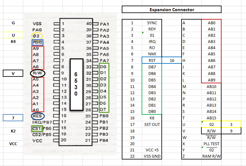
I think I have actually figured out why my breadboard project was not working, when I first tried it. I did not have pull up resistors on RS0 (K4) or CS1 (K2)
I just added them, and it did make a big difference.
It looks like my PAD and PADD and PBD and PBDD are working, … I can set them up as either input or outputs.
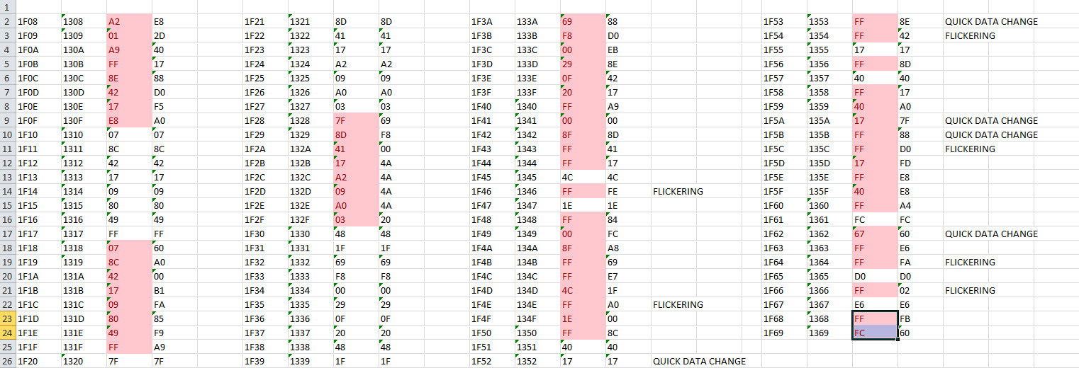
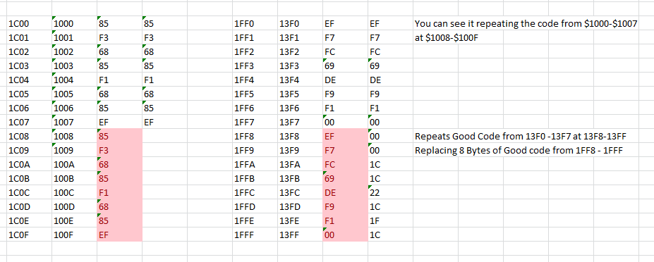
However the ROM portion is still off. Although I did notice a pattern. It looks like it is repeating 8 bytes of good code, there by replacing 8 bytes of good code.
It does this all the way throughout the ROM.
Now here is a question that just ran through my mind. If I had to replace the 6502 and the 6530-002, because they were both bad.
What is the chance that the 6530-003 is good??? :o(
Although I think I might still be able to boot up, even if it is not working correctly. We will see soon.
Jeff M. Nay
Here is a reply from Bob Applegate of Corsham. I asked him about using a Arduino Nano or Pico
I think the Nano can handle up to 5.5V
HI Jeff,
I did work on emulating a 1793 disk controller using a much faster processor, but maybe an Arduino Mega could do the job of emulating a 6530. It is only running at 16 MHz… lots of work to do very quickly to keep up with a 1 MHz 6502.
Two 8 bit ports can handle all the select, phase 2, /RESET and R/W inputs and two address bits, another 8 bit port having the other 8 address bits, and another bidirectional port for data.
It would be tough to get the code to be fast enough as it would need to decode the selects, possibly do a look-up of either ROM or RAM based on the address, present data on reads, etc.
Arduinos are 3.3 volt devices? Might need to buffer the voltages but probably not.
Let me know how it works out ;-)
Bob
From: h.o...@hansotten.com [mailto:h.o...@hansotten.com]
Sent: Monday, August 08, 2022 10:52 AM
To: 'Jeff M. Nay'
Subject: RE: KIM-1 Troubleshooting
A Raspberry Pi Pico with level translators could do that.
And I have seen a Teensy 4.1 to be a 6502 CPU.
So it can be done.
A 6532 and a ROM is what the replacement board is about, it works.
From: Jeff M. Nay <nove...@gmail.com>
Sent: Monday, 8 August 2022 16:11
To: h.o...@hansotten.com
Subject: RE: KIM-1 Troubleshooting
Double checked all address lines again. All Good !!!
Any microcontroller ideas, to replace either 6530 ???
I heard that we have a pretty good programmer in the group…
From: h.o...@hansotten.com [mailto:h.o...@hansotten.com]
Sent: Monday, August 08, 2022 9:26 AM
To: 'Jeff M. Nay'
Subject: RE: KIM-1 Troubleshooting
The second 6530-003 has the tape ROM, and has the free I/o ports (the ones connected to that rely card).
The KIM-1 will happily boot and function with it if it is not present (like a standard PAL-1 :) )
So remove if that is possible until the KIM-1 is alive again.
Sure the address lines are well connected A3? to the breadboard since the 8 byte pattern?
--
You received this message because you are subscribed to a topic in the Google Groups "KIM-1" group.
To unsubscribe from this topic, visit https://groups.google.com/d/topic/kim-1/gp3fQWp5rS4/unsubscribe.
To unsubscribe from this group and all its topics, send an email to kim-1+un...@googlegroups.com.
To view this discussion on the web visit https://groups.google.com/d/msgid/kim-1/025601d8ab25%240a7d8ed0%241f78ac70%24%40gmail.com.
Hans Otten
Teensy based, fast enough to emulate cpu's like 6502. Well documented.
Hans Otten
Jeff M. Nay
I am currently simply using a logic probe to look at signals. Is it active (B), Low (L) or High (H) and comparing them to a working KIM-1
Since adding the Corsham 6530-002 replacement. I am seeing a much better set of signals going to the U4 (74145) decoder. One display is partially active.
I am still receiving several bad signals coming in and going out of U24 (74145) decoder. So, I replaced it, but still seeing the same bad signals.
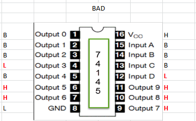
Looks like I have a bad input D on pin 12 which is going low – This one concerns me the most, as I believe this input comes from my 6530-002 replacement. Which should be good. I checked pin 21
Of U2 (6530-002) and it is also Low. I am also seeing a low on pin 4 (Output3) and I am seeing a high on pins 6,7 and 9,10,11 (Output 5,6,7,8,9)
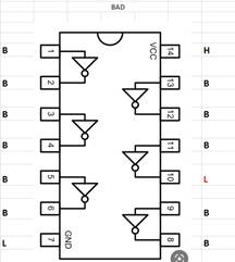
Looking at U17 (7406) I have one bad signal on pin 10 seems to be stuck low (This seems impossible unless 7406 is bad)
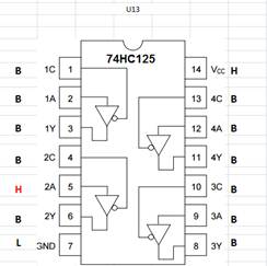
Looking at U13 (74125) one bad signal on pin 5 which is stuck high. I have also noticed the Output pin 12 on U6 (memory) is high – possibly bad memory chip. When I try
to piggy back, I get no display at all and pin 12 is still stuck high.
So, right now I am considering replacing U6-2102 Memory and U17-7406 Inverter. Anybody have any suggestions on why I am getting so many bad signals on U24-74145?
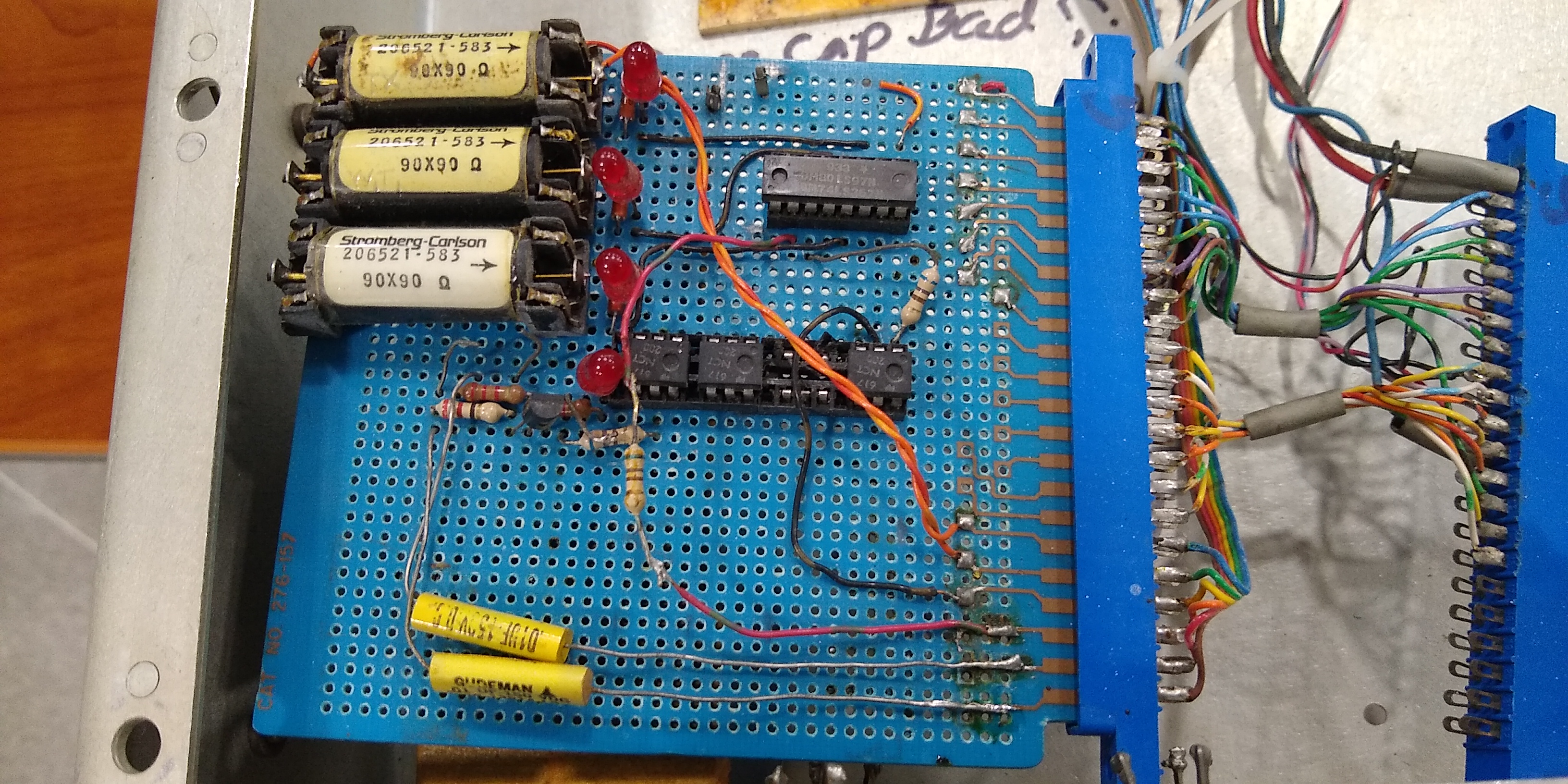
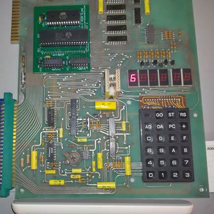
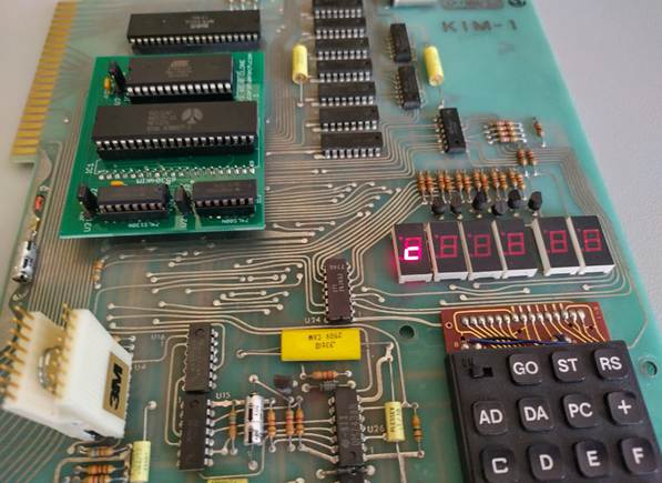
I went ahead and piggy backed the 7406 and did see a difference in the display. Now instead of a small c showing up, in the left most display. I see a full sized 6. See pics bellow.
However I believe that pin 10 is still being held low, so I am not sure why it made a difference at all.
I guess my main concern is why I am not receiving the correct Inputs on U24 74145. A,B,C and D should all be receiving proper inputs from the 6530-002 replacement.
I have of course tried replacing U24 with a new chip, but no change.
I will try to get a video created, showing what signals I am seeing, using a logic probe on U24 and at U6. Where I have pulled the suspected bad memory chip.
I will try to display what good signally should look like, using my working KIM-1 and then display what is showing up on the non-working KIM-1 for comparison.
I would love to hear any and all inputs. This is a board with multiple failures, so it will not be a simple fix. One thing at a time, I guess…
Looking at the schematics, I might want to start looking at U15 and U16, which controls the R/W and the φ2 and φ2 NOT. I will probably
Have to break out the OScope to take a look at these signals. Unless my probe shows that there is something not working.
U24 - 74145 | U17 - 7406 | U13 - 74125 |


From: ki...@googlegroups.com [mailto:ki...@googlegroups.com] On Behalf Of Hans Otten
Sent: Wednesday, August 10, 2022 3:06 AM
To: KIM-1
Subject: Re: KIM-1 Troubleshooting
5V adapted, small enough to fit a 40 pin IC.
--
You received this message because you are subscribed to the Google Groups "KIM-1" group.
To unsubscribe from this group and stop receiving emails from it, send an email to kim-1+un...@googlegroups.com.
To view this discussion on the web visit https://groups.google.com/d/msgid/kim-1/48d941e1-72ca-4400-8714-0ab26379e08cn%40googlegroups.com.
Jeff M. Nay
I have just finished uploading the video that I created today. Thought you all might like to take a look. It gets real interesting at the very end.
And it definitely points to the memory being the main problem, at this time. So, watch to the very end.