DB9MAT MRF-101 100 W HL2 PA: ready for "prime time?"
1,369 views
Skip to first unread message

nekv...@gmail.com
Oct 15, 2020, 4:27:31 PM10/15/20
to Hermes-Lite
I would like to use the fine work of Mathis et al as the basis of a 100-W EER companion to HL2.
A review of the schematic indicates that a drop-in of my circuitry would be straightforward.
Has the current r0.3 hardware been built and tested well enough to be used as the basis for this new project? I am primarily concerned about the monitoring and control functions.
Thanks and 73 to all,
Brian K1LI

Matthew
Oct 17, 2020, 11:55:15 AM10/17/20
to Hermes-Lite
Sorry for the delay in replying, I've been preoccupied with a last minute rush for antennas for the Pre-Stew contest tonight.
I haven't really made as much progress with the HL2-MRF101 as I would have liked recently. I really must get a move on for CQWW at the end of November. I have been able to set the bias, but I haven't properly got the software readout of temperature or current implemented properly yet. Not you what you mean by control, but I am confident in all the filters/relays.
I would very much consider this as joining in an experiment rather than buying proven hardware for now.
73 Matthew M5EVT.

Steve Haynal
Oct 18, 2020, 4:26:22 PM10/18/20
to Hermes-Lite
H Brian,
I have a spare circuit board which I can send you if you are really interested in building one up.
73,
Steve
kf7o

mathis.s...@gmail.com
Oct 19, 2020, 5:19:49 AM10/19/20
to Hermes-Lite
Hi all,
I agree with Matthew. The PA itself has proven to be quite stable, as have the filters and relays. Setting the bias is doable with SparkSDR (or any I2C adapter.. ;)), but current and temperature monitoring are not yet implemented in the gateware, or at least not properly tested.
So while I don't see any major problems or road blocks with the PA companion, it's still an experiment to me and I'd like to see a couple more builds of it before calling it "done".
73s,
Mathis

st...@radio-kits.co.uk
Oct 19, 2020, 5:50:06 AM10/19/20
to Hermes-Lite
Hi Mathis,
Wondered if you have measured the IMD or harmonics at the antennae connector, looking to build one but concerned about the 2nd harmonic from bands with shared LPF.
Steve G6ALU
--
You received this message because you are subscribed to the Google Groups "Hermes-Lite" group.
To unsubscribe from this group and stop receiving emails from it, send an email to hermes-lite...@googlegroups.com.
To view this discussion on the web visit https://groups.google.com/d/msgid/hermes-lite/13a9cf27-85c8-4bc3-be58-0e219ec35e34n%40googlegroups.com.
mathis.s...@gmail.com
Oct 19, 2020, 6:09:46 AM10/19/20
to Hermes-Lite
Hi Steve,
I have not yet done those measurements, but both M5EVT and WA2EUJ, whose filters I am using, have examined the filters:
73s,
Mathis, DB9MAT
nekv...@gmail.com
Oct 19, 2020, 2:54:41 PM10/19/20
to Hermes-Lite
Thanks for the offer, Steve, but I have to make so many changes that the existing board won't be useful.
Once the schematic capture is complete, I will post my design to GitHub for public comment before proceeding to layout. I'll also provide the LTSpice simulations that have convinced me of the efficacy of the amplifier's basic design.
I need to contact MakerFabs to discuss PCB options. Should I work with a "Hermes-Lite" contact, or just submit a general query?
== Brian K1LI
Steve Haynal
Oct 21, 2020, 12:38:29 AM10/21/20
to Hermes-Lite
Hi Brian,
Just go through their web page. jlcpcb.com is also good and inexpensive. See www.pcbshopper.com.
73,
Steve
kf7o
Matthew
Dec 6, 2020, 11:49:30 AM12/6/20
to Hermes-Lite
Unfortunately, I didn't hit my self-imposed deadline of having this ready for CQWW last weekend. I used my HR50 instead and enjoyed over 600 QSOs with the HL2+HR50+linHPSDR, but I'm sure an extra few dB of power out might have got me a few more mults :)
Building this PA has been an interesting experience. The HR50 is the only non-QRP amplifier I have ever built and all the design decisions are already done with that. With the HL2-MRF101 there is lots to think about for heat, high(er) current and strong RF signals. Not mention having to homebrew a dummy load to handle 100 W.
I replaced the FPGA and digital pot on my 2nd HL2. I set the HL2 PA bias again and I was ready to carry on where I left off. I am updating the main GitHub repo with issues as I find them.
For now, I have chosen a small copper heatsink as recommended on the rfpowertools group. I have the fan set "always on" at the moment. A quick looks shows no additional HF noise (this could change with more fancy PWM).
I have set the MRF101 PA bias to 100 mA with a value of 163 sent to the digital pot. Initially I had issues getting power, I had to reflow the small inductor on the gate of the MRF101 and I was producing RF.
In linHPSDR, with drive set 100%, I have settled upon the following settings:
Band Current Power PA cal
160 3.57 105 39.1
80 3.36 105 42.7
60 3.3 100 40
40 3.54 100 39.1
30 2.69 90 38.8
20 2.75 100 44.0
17 3.01 100 41.4
15 2.77 100 40.9
12 3.11 100 42
10 See below
On 10m I am having issues where the current limiting is setting in on my PSU (48 V @ 5 A). Sticking a scope probe on the gate of the MRF101 changes the behaviour and allows me to get around 90 W of RF out, however, if I push the drive level further, the current limiting sets in. I think Mathis mentioned having issues with her power on 10m. Perhaps there is a tweak to the circuit to improve operation on 10m around the gate of the FET?
On 20m to 12 m for an unknown reason the fan on the heatsink stops (but I can see there is still 12 V going to it) when I transmit. Has anyone experienced a fan turning off in the presence of RF (or perhaps magnetic coupling to the filters?)? The fan and heatsink do seem to keep the FET temperature in good order (from my testing so far).
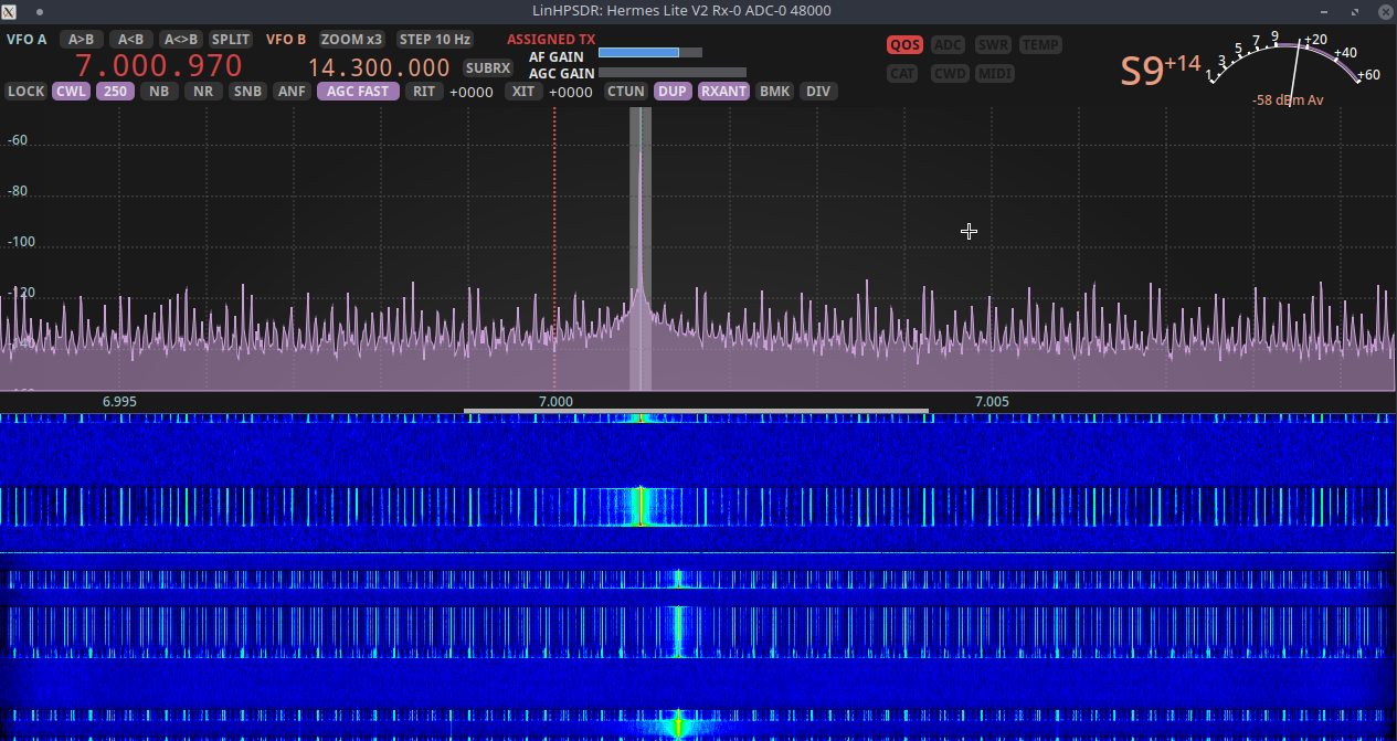
I am monitoring the signal that is being transmitted using duplex setting in linHPSDR. Initially, I was a little concerned that there were close in spurs, changing the antenna source for the rx to be the dedicated RX antenna shows a much cleaner signal. I think this is because the RX antenna route provides more isolation from the TX antenna compared to the TX/RX relay alone. On 40m if I set the drive level too high (to go very slightly over 100 W) I see very bad close in spurs. I have attached a screenshot. Looking at the stack of PCBs, the 40m TX filter is right over the modem IC (ADC/DAC) with a vertical separation of 2 cm. Perhaps some folks who use external amps and can monitor duplex in their SDR software can comment on what their duplex monitored signal looks like? Am I seeing overload on RX or am I simply sending a poor signal? I don't own a spectrum analyser.
73 Matthew M5EVT.
Steve Haynal
Dec 7, 2020, 1:24:11 AM12/7/20
to Hermes-Lite
Hi Matthew,
Interesting discussion. Do you think adding shielding between the PA and HL2 board would help?
73,
Steve
kf7o
Matthew
Dec 7, 2020, 12:05:48 PM12/7/20
to Hermes-Lite
Hi Steve,
Yes, I suspect a thin sheet of aluminum between the 2 boards would help. I'm going to look at adding something.
I did manage to control the fan issue with a ferrite clamped around the power leads for the fan.
I would love to hear if Jim WA2EUJ has any ideas regarding my 10m problem that can be "fixed" by attaching a scope probe to the gate of the FET. A scope probe fixing a problem makes it a little harder to see what is going on!
73 Matthew M5EVT.

James Ahlstrom
Dec 7, 2020, 12:56:29 PM12/7/20
to Hermes-Lite
Hello Matthew,
An "active probe" may be useful to see what is happening on 10 meters. It is a high impedance (0.5 pF) buffer to 50 ohm output, and is a much lower load than a scope probe. Try eBay and the other usual suspects.
Jim
N2ADR

Scott AK5SD
Dec 7, 2020, 1:16:47 PM12/7/20
to Hermes-Lite
"On 10m I am having issues where the current limiting is setting in on my PSU (48 V @ 5 A). Sticking a scope probe on the gate of the MRF101 changes the behaviour and allows me to get around 90 W of RF out, however, if I push the drive level further, the current limiting sets in. I think Mathis mentioned having issues with her power on 10m. Perhaps there is a tweak to the circuit to improve operation on 10m around the gate of the FET?"
This sounds like it might be a parasitic oscillation. You can scope the output of the amplifier to look for it. Putting the scope probe on the gate of the MRF101 adds capacitance to that node which may improve the stability. If the current limiting only kicks in when you are trying to drive 100W (but is fine at lower power levels), then the efficiency on the 10m band may not be good enough for the power supply that you have (48W x 5A = 240W). If the efficiency is less than 42% (not including other loads on the power supply), then the supply will limit.
Scott
AK5SD
Matthew
Dec 7, 2020, 2:42:09 PM12/7/20
to Hermes-Lite
Jim, thanks for the suggestion, sounds like a very useful tool to add to my kit.
Scott,
Thanks for your comments. Yes, some sort of oscillation was my suspicion, I don't have very good scope probes so I am probably adding enough capacitance between the ground and the gate to stabilise it a little. With no scope probe connected (regardless of drive level) the current limiting on the supply kicks in. I can get the full 100 W on 12m and only draw 3.11 A, so I would be surprised if the efficiency drops off enough going up to 10m that it draws an extra 1.9 A, but at this point I'm receptive to all ideas.
I deliberately kept the layout of this part of the circuit exactly as Mathis but I don't think he has had any problems. As far as I'm aware Mathis is the only other person who has built this PCB and tested it at full power. Marc F6ITU has sent me a message to say he hasn't tested full power on all the bands yet.
73 Matthew M5EVT.
Matthew
Dec 13, 2020, 12:03:39 PM12/13/20
to Hermes-Lite
I have focused on the instrumentation this week. I can read the ADC current and temperature (via I2C software read/writes). The temperature suffers from a lot of noise during TX, so much so that the average temperature reading ends up being a little low during TX. I'm not aware of anything in the protocol that allows the fan to be turned on/off, so for now I have the fan on all the time. The heatsink I mention in a post above has proven to be a good choice. I think a better way to handle the ADC would be with a small micro-controller. This could sit on its own I2C bus, do all the temperature averaging etc and control the fan.
As far as I can tell I have the ADC correctly setup in scan mode, but the HL2 I2C read only reports the first 16 bit result (in RDATA [31:16] and RDATA[15:0], so it requires 2 ADC reads via protocol 1 for what should be able to fit in the 32 bit wide RDATA. Does this sound correct Steve? Should I be able to get x4 8 bit words from an I2C read sent back via protocol 1? I can see on a scope that the 4 8 bit words are sent from the ADC to the HL2.
To answer the original question to this message, I would consider the control and monitoring functions as proven to be working now. However temperature read out would probably benefit from some additional method to combat the noise. I would also strongly recommend thinking about using a micro-controller between the ADC and the HL2.
73 Matthew M5EVT.
Steve Haynal
Dec 13, 2020, 9:41:40 PM12/13/20
to Hermes-Lite
Hi Matthew,
I don't think there is a fan on/off in the protocol. If you are using the FPGA-generated fan PWM, then that goes on at different speeds at different temperatures. The details are in the wiki.
I don't understand how you are reading the slow ADC via the i2c software interface. The slow ADC for temperature/current/fwd power/rev power is on a separate i2c controller which reads values frequently enough to return new values with each HL2->PC packet. This i2c controller is not directly accessible via software and the register can't be read directly. I must be missing something here.
I would love to see an ESP32 module or similar integrated with the HL2. I think that would open up a lot of possibilities and reduce burdens on the gateware.
73,
Steve
kf7o
Matthew
Dec 14, 2020, 12:48:29 PM12/14/20
to Hermes-Lite
Hi Steve,
Apologies, I wasn't clear in my message. The HL2-MRF101 PCB has a MAX11645 ADC on ADDR 0x36. This monitors MRF101 current and MRF101 temperature. The ADC is connected to the HL2 SCL2 and SDA2. I am accessing this through ADDR 0x3d in the HL2 protocol.
In general I have noticed that the HL2 temperature (as reported by the gateware) follows the trend of the MRF101 temperature, so controlling the fan based on the HL2 temperature rather than MRF101 temperature doesn't seem too bad a compromise.
73 Matthew M5EVT.
Steve Haynal
Dec 15, 2020, 1:30:07 AM12/15/20
to Hermes-Lite
Hi Matthew,
The response data from i2c is 32-bits. See i2c_bus2. You can see in slow_adc.v how all entries are read in one long read. I'll have to study the code a bit more to see if/why there are problems with 32-bit reads.
73,
Steve
kf7o

David Ricciardi
Dec 17, 2020, 2:22:53 PM12/17/20
to Hermes-Lite
There seems to be a conflict in the BOM here https://raw.githubusercontent.com/mathisschmieder/HL2-MRF101/master/bom/HL2_MRF101_r03.csv for K13,K11 it shows EC2-3NU for the part number but the farnell product id is for EC2-12NU. which one is right here?
Matthew
Dec 17, 2020, 2:35:31 PM12/17/20
to Hermes-Lite
Well spotted. The EC2-12NU is the correct part.
73 Matthew M5EVT.
David Ricciardi
Jan 8, 2021, 2:06:01 PM1/8/21
to Hermes-Lite
So I have been building up a MRF-101 amp here over the holidays and just finally got the last of the parts in to assemble it. I did have a couple questions though about assembly and final testing hopefully someone can answer for me...
1) R40 & R41 do both of these get jumpered? or just one? based on the bom it kind of looks like both, but i'm not really sure.
2) Testing filters.... I had been reading though https://wiki.electrolab.fr/Projets:Lab:2020:Ampli_100W (great resource btw) and he has the steps he used on the old board revision... are these still accurate?
- Temporarily solder an SMA connector on J2-2 / J2 / 1 (see photo)
- Temporarily solder an SMA connector to point 3 of T1 after lightly scraping the sparing varnish to release a ground point for the connector in question.
- Solder (still temporarily) a 10 or 12 cm "walking" wire connected to the mass at one end, the other end stripped and tinned to 2mm. It will serve as a control wire to switch the filters one by one.
3) Bias adjust... I never had to do this for the hl2 so i guess i'm just not sure what to expect.. is it as simple as going into SparkSDR checking the enable bias setting and adjusting till the value is 100?
To test some of the circuits as I have gone through the build I have hooked the board up to my arduino and was able to detect 3 i2c devices on the board, and was also able to use the MCP23008 library to switch all the relays so I have been able to test some of this without connecting it to a hl2, but I was wondering if anyone had any other suggestions on potential things to check before connecting the board up to anything?
Thanks in advance! And sorry if these have been answered elsewhere I tried looking around but didn't find anything.
Matthew
Jan 8, 2021, 2:47:17 PM1/8/21
to Hermes-Lite
Hi David,
Good to hear someone is building a PCB up. I've been using mine for the past month or so on the air. I will try to answer your questions:
1 - Regarding filters/sma connectors - do you have a VNA? How are you connecting the HL2 to the PCB? I made a temporary cable that routed 3V3, GND and i2c signals to the HL2-MRF101 PCB, I soldered an SMA to HL2-MRF101 connector J2 pin 6. Then connected a 50 ohm load to the antenna connector.
2 - Fit *either* R40 or R41. I soldered R41, but note this. (My logic for this is to eventually have an option to leave the HL2 TX/RX relay always in TX and this HL2 relay is controlled by INTTR.
3 - Re: bias. You need a method to measure current on the 48 V line. I hooked up my DVM, selected SSB mode, made sure there was not audio, enabled PTT, then set the bias for 100 mA on the 48 V supply line. The value in SparkSDR is arbitrary and has no relation to actually current (correct me if I am wrong Alan!). Please say if this explanation isn't clear enough.
4 - I suggest listening in receive and cycling through the bands to confirm that the filters are working as you expect. If you haven't already, you probably want to tweak the PWR measurement resistors. I suggest hooking up a DVM to the LM35 pin and monitoring the temperature (SparkSDR doesn't report this) on the DVM (10 mV/degC) for you first few trials with the PA.
5 - Depending on your software you will need to tweak you drive level per band. What software are you planning to use? If you have an interest in linHPSDR let me know and it might give me the encouragement to get on with sharing me HL2-MRF101 tweaks (temperature read out and correct power measurement) for linHPSDR (which I plan to but haven't go round to yet).
6 - If you want to use the RX antenna option, you want to fit R36.
73 Matthew M5EVT.
Scott AK5SD
Jan 8, 2021, 3:12:41 PM1/8/21
to Hermes-Lite
This question has been bugging me since I saw the original design so I'm just going to ask it.
The PA uses a single transistor biased at a relatively low current. This transistor will be off for (most of) 1/2 of the input waveform. It is not a push-pull design where one transistor conducts for 1/2 cycle and the other conducts for the other 1/2 cycle. Therefore, this is more like a class-C design than a class-AB design. I would expect the distortion to be high. Harmonic distortion can be filtered out with the lowpass filters but IMD cannot. Has anyone measured the IMD performance of this design?
73,
Scott
AK5SD

Duncan Clark
Jan 9, 2021, 6:42:36 AM1/9/21
to herme...@googlegroups.com
https://sites.google.com/site/rfpowertools/home/nxp-mrf-101
https://sites.google.com/site/rfpowertools/home/nxp-mrf-101/test-data
Of course if you run PureSignal you could run it as class B all day long
and PureSignal will correct everything.
https://fairlawnarc.com/eme-info/PDF/N1JEZ-2.pdf
Duncan
In message <bf0edcf8-1455-4833...@googlegroups.com>,
Scott AK5SD writes
>This question has been bugging me since I saw the original design so
>I'm just going to ask it.
>
>The PA uses a single transistor biased at a relatively low current.
>This transistor will be off for (most of) 1/2 of the input waveform. It
>is not a push-pull design where one transistor conducts for 1/2 cycle
>and the other conducts for the other 1/2 cycle. Therefore, this is more
>like a class-C design than a class-AB design. I would expect the
>distortion to be high. Harmonic distortion can be filtered out with the
>lowpass filters but IMD cannot. Has anyone measured the IMD performance
>of this design?
>
>73,
>Scott
>AK5SD
--
>I'm just going to ask it.
>
>The PA uses a single transistor biased at a relatively low current.
>This transistor will be off for (most of) 1/2 of the input waveform. It
>is not a push-pull design where one transistor conducts for 1/2 cycle
>and the other conducts for the other 1/2 cycle. Therefore, this is more
>like a class-C design than a class-AB design. I would expect the
>distortion to be high. Harmonic distortion can be filtered out with the
>lowpass filters but IMD cannot. Has anyone measured the IMD performance
>of this design?
>
>73,
>Scott
>AK5SD
Duncan Clark
G4ELJ

WA2EUJ
Jan 9, 2021, 2:56:35 PM1/9/21
to Hermes-Lite
Hi Scott,
-38 dBc on 80M, -41 dBc on 20M and -39 on 6M.
The amp is very linear, you can see the plots here:
-38 dBc on 80M, -41 dBc on 20M and -39 on 6M.
I'm not sure what makes you think that the MOSFET will be off for any portion of the cycle. The drain current is determined by the gate voltage. When RF is added to the gate bias voltage, the bias increases and more current flows. It's similar to how single triode vacuum tube amplifiers are biased for Class AB. Most tube amps only have a single tube and in amps with multiple tubes generally in parallel not push-pull.
The best way to use multiple MOSFETs is not push-pull either, narrow band amplifiers use Doherty power amplifiers that have 90° hybrids on the input and output of one of the MOSFETs so the output of one device arrives 180° out of phase with the output of the other then the two output are combined causing a cancellation of power in the terminated port and doubling of power in the coupled port.
Broadband dual MOSFET designs typically do not operate push-pull either with one device off while the other is on, the input is split in a 180° hybrid so the outputs are applied to either end of a balanced transmission line transformer which acts as a balun and impedance transformer. It's less efficient than the Doherty design but it gets the job done.
73,
Jim WA2EUJ
David Ricciardi
Jan 9, 2021, 5:19:24 PM1/9/21
to Hermes-Lite
Thank you for the feedback, I think all of this makes sense. I
was/am planning on using my nanovna to check the filters hopefully its
good enough for the task.
I am a bit surprised about #3 though, looking at the amp board it looks like it has current monitoring on the 50V line with U7/INA193. Setting up external current monitoring is certainly not a big deal though.
I am a bit surprised about #3 though, looking at the amp board it looks like it has current monitoring on the 50V line with U7/INA193. Setting up external current monitoring is certainly not a big deal though.
Matthew
Jan 10, 2021, 4:54:15 AM1/10/21
to Hermes-Lite
You are correct that there is on board monitoring for temperature and bias current. However, the gateware does not interact with this. PC software must communicate with the ADC via the i2c read/write capability in the gateware. Hence, you rely on the PC software implementing this (you can access i2c via hermeslite.py too). I can read the current via the i2c lines on in the PC, however, it suffers from noise and has potential to give a false reading. See here. I think a future rev of board should have a small micro and take care of the ADC and data smoothing. It would be good to try and understand how to combat this noise too.
73 Matthew M5EVT.
Scott AK5SD
Jan 10, 2021, 1:29:32 PM1/10/21
to Hermes-Lite
Hi Jim
Thanks for the reply. The data speaks for itself.
100W into 50 ohms is 1.4A RMS, or 2A peak current. The output impedance seen by the transistor is less than 50 ohms due to the output transformer. It looks like a 1:4 impedance ratio, so the transistor sees 12.5 ohms. This means the peak output current of the transistor is 4A, not 2A like at the RF output. Now, if you bias the MOSFET at 100mA and then superimpose the RF signal on top of that, the RF current will increase by 4A on the positive peaks and decrease by 4A on the negative peaks. Without feedback, this means the peak output current is 4.1A on the positive swing and -3.9A on the negative swing. Clearly, the current can't go negative and so the device just shuts off. The same analysis can be done at the gate of the transistor. If you bias the device at 100mA, the gate voltage is only slightly above the threshold voltage of the MOSFET. When you superimpose the RF input voltage onto the bias voltage, the gate potential will fall below the threshold voltage on the negative peaks.
I think the explanation is that the use of heavy shunt-shunt feedback is preventing the transistor from shutting off on the negative input peaks. As the RF input voltage decreases, the output voltage rises (inverting amplifier) and a positive feedback voltage is superimposed on the input RF waveform from the feedback path due to R1, R6, R7, and R8 that counteracts the decline in the input voltage. According to my calculations, the voltage gain to the drain of Q1 is about 5, so the reflected input impedance from the Miller feedback is about RFB/(AV+1) or 100 ohms. This is a high amount of shunt feedback. Without it, I think this amplifier would not be linear at all. By contrast, you can make a linear amplifier using two transistors in a 180 degree split hybrid situation (I don't see a difference between push-pull and 180 degree hybrid) without the use of feedback. Feedback can make the linearity even better in that case however.
73,
Scott
AK5SD

airp...@gmail.com
Jan 21, 2021, 2:24:20 PM1/21/21
to Hermes-Lite
Apologies if I'm misappropriating a thread, but...
Does anyone here in North America have an extra (current revision) MRF-101 board available? My bench is now clear enough that I'd like to go ahead and build one up to experiment with.
If not, I can get some boards fabbed, but I really only need one at the moment.
steve.c - k7unx
David Ricciardi
Jan 21, 2021, 2:45:13 PM1/21/21
to Hermes-Lite
I do have 2 extra boards I can send out, if you are fine with covering shipping (~$6 based on the last one i sent out) I will be happy to send you one. If anyone else wants the 2nd one be nice to take care of both at the same time :)
If that sounds good to you steve.c (k7unx) is your qrz address accurate? May be a few days though before I get a chance to send them out.
If that sounds good to you steve.c (k7unx) is your qrz address accurate? May be a few days though before I get a chance to send them out.

jason kitchens
Jan 21, 2021, 2:52:56 PM1/21/21
to David Ricciardi, Hermes-Lite
I'd take one if it's still available.
Jason
KV4TE
--
You received this message because you are subscribed to the Google Groups "Hermes-Lite" group.
To unsubscribe from this group and stop receiving emails from it, send an email to hermes-lite...@googlegroups.com.
To view this discussion on the web visit https://groups.google.com/d/msgid/hermes-lite/0b20b55d-bd87-4b5c-af38-658660b4b4b1n%40googlegroups.com.
David Ricciardi
Jan 21, 2021, 3:40:27 PM1/21/21
to Hermes-Lite
Cool, yep its yours. Jason & Steve.C let me know if there is a problem with your qrz address otherwise I will ship these both out here in a few days. Also if you both could ping me at nricciar[at]gmail[dot]com whenever you get a chance so I can send you the tracking number & what the shipping cost ended up being.
airp...@gmail.com
Jan 21, 2021, 4:08:44 PM1/21/21
to Hermes-Lite
David, thanks! The QRZ address is valid, and I've confirmed as such in a separate email.
- steve.c - k7unx
Steve Haynal
Jan 22, 2021, 1:09:14 AM1/22/21
to Hermes-Lite
Hi Jim,
Thanks for your pointers. In case people don't recognize the call, Jim is the designer of the popular hardrock-50 HF amp. He also took first place in last year's NXP Homebrew RF Design Challenge.
73,
Steve
kf7o
WA2EUJ
Jan 22, 2021, 9:43:06 AM1/22/21
to Hermes-Lite
Hi Steve,
I also have in the works a MRF101 board that is a drop-in replacement for the amp board in the Hardrock-50 so if you don't mind running 50V, you can have a very small 100W amp.
If anyone is interested in experimenting with any of these amp, let me know and I'll get you the technical info.
73,
Jim WA2EUJ

Kristofer Danner
Jan 22, 2021, 7:00:09 PM1/22/21
to Hermes-Lite
"I also have in the works a MRF101 board that is a drop-in replacement for the amp board in the Hardrock-50 so if you don't mind running 50V, you can have a very small 100W amp."
Ready to buy! Or I'll buy a whole another HR50 enclosure, etc with that board if you'll sell it to me that way, so I can keep my current HR50 intact.
KD
WA2EUJ
Jan 23, 2021, 3:47:19 PM1/23/21
to Hermes-Lite
It will be a while before it's an actual product, since we are just settling into selling and supporting the Hardrock-500. We had hoped that the $25 copies of the VRF2933's would be OK but they aren't so we have to get $127 ea. VRF2933's from Digikey which adds to the price and makes the amp not as cost effective against other 500W amps. It's still a good value and one of the lightest 500W amps available, just over 8 Kg with the ATU installed (18# for metrically challenged).
The 100W upgrade for Hardrock-50 needs a new amp board and a new front panel which has a small color graphics display based on the Hardrock-500's graphics with a lot more info than the HR50's display. The rear paned and ATU will be the same but for loads over 5:1 the power will be restricted to 50W to prevent damaging the ATU. If I redesigned the ATU to fit in the same place with larger components, the tuning range would be limited anyway.
I do have a few bare boards for the amp and control board and the Front Panel Express files if anyone wants to try building one. Lots of tiny SMT parts. BOM and FW are available.
Jim.

George Smart (M1GEO)
Feb 1, 2021, 8:36:20 AM2/1/21
to Hermes-Lite
Myself and Jonathan GW2HFR brought up 3 amplifiers last night, with several errors found. We were first caught out by the K11/K13 relays - I had ordered from Digikey, and had 3V parts fitted - they get hot on 13.8V :)
Another thing I notice is that the 5W power attenuator gets hot. This attenuator is quite close to the thermal tracking on Q1. I notice the thermal tracking seems to reduce the bias value quickly, causing the output power to gradually drop.
I took the liberty of removing C75 & C76 and using a 220nF capacitor to couple into an SMA; I then see around 95W on 10m, but the lower bands (says 160m) struggle to make 50W - this is not a reactance issue, but could well be an impedance issue. Are the low-pass filters part of an impedance matching network?
I think the amplifier broadly works; the next job is to sweep all of the LPFs.
Thanks.
George M1GEO (definitely not an RF engineer!)
Matthew
Feb 1, 2021, 3:09:39 PM2/1/21
to Hermes-Lite
Hi George,
Good to hear of a few more being built.
Sorry you missed the issue on gitlab about the relays. I've added a few more notes to the issues list on gitlab today. I would like to eliminate the attenuator, but we need someone with an SA to quantify IMD @ 5 W vs 1-2W with the HL2 to understand if we can get away with it. Thermal management of the stack of these 2 boards is a bit more challenging than one might think. Please do update the github issues list with any comments/observations/findings.
I was suffering from lack of sleep but I think I might have blown the MRF101 FET on my board at the weekend in CQWW160. I had to switch over to my HR50 (and lost 2 dB of much needed output!). I need to catch up on sleep and investigate.
I'm moving towards putting this in a more permanent enclosure with a 2nd HL2 for coherent rx. It turns out that mini ITX PC cases seem to be one of the cheaper ways of doing this with something that looks reasonably nice. I know Steve joked in the past that someone will one day use water cooling for the HL2 5 W PA one day, maybe I can factor this in with the PC case...
73 Matthew M5EVT.
Scott AK5SD
Feb 1, 2021, 4:24:22 PM2/1/21
to Hermes-Lite
I have access to a R&S FSWP high-end phase noise meter with the spectrum analyzer option. This is my go-to box for large-signal testing. I also have a clean RF signal source and 50V power supply. If somebody wants to send me a fully functioning board, I can take whatever measurements you want. I don't really have time to build one up myself.
73,
Scott
AK5SD
Matthew
Feb 1, 2021, 4:30:46 PM2/1/21
to Hermes-Lite
Hi Scott,
Do you have an HL2?
All I would like to know is how much worse (if at all) the close in IMD is from the HL2 TX output at 1-2 W vs the full 5 W (adjusted simply using the "Drive level" control in whichever software is used). No HL2-MRF101 PCB needed for this.
73 Matthew M5EVT.
Scott AK5SD
Feb 1, 2021, 4:58:53 PM2/1/21
to Hermes-Lite
Yes, I have an HL2. I misunderstood what you wanted. I have two RF signal generators and a combiner (for testing a PA) but not a two-tone audio source (for testing the HL2). I might be able to track one down, but in the meantime do any of the SDR clients that work with the HL2 have a two-tone generator built in?
73,
Scott
AK5SD

Alan Hopper
Feb 1, 2021, 5:14:27 PM2/1/21
to Hermes-Lite
Hi Scott,
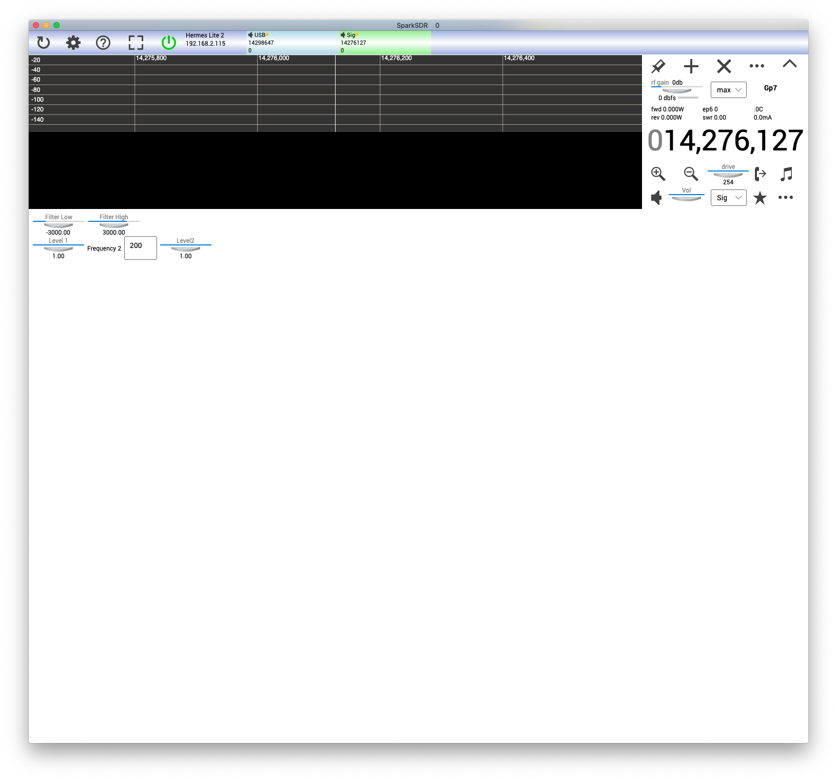
SparkSDR can generate two tones if you select Sig for the mode, not very sophisticated but should do the job.
73 Alan M0NNB
Duncan Clark
Feb 1, 2021, 5:32:48 PM2/1/21
to herme...@googlegroups.com
In message <8de48920-9920-46d3...@googlegroups.com>,
Scott AK5SD writes
I would use Reid's version:
https://github.com/mi0bot/OpenHPSDR-PowerSDR/releases/
Having said that, if one is worried about IMD (and one should always be)
then use PureSignal with PowerSDR, or a.n.other software that supports
it. I see no reason not to be using PureSignal if the option is there.
Duncan
--
Duncan Clark
G4ELJ
Scott AK5SD writes
> do any of the SDR clients that work with the HL2 have a two-tone
>generator built in?
PowerSDR.
>generator built in?
I would use Reid's version:
https://github.com/mi0bot/OpenHPSDR-PowerSDR/releases/
Having said that, if one is worried about IMD (and one should always be)
then use PureSignal with PowerSDR, or a.n.other software that supports
it. I see no reason not to be using PureSignal if the option is there.
Duncan
--
Duncan Clark
G4ELJ

Graeme Jury
Feb 1, 2021, 5:47:21 PM2/1/21
to herme...@googlegroups.com
Quisk in full duplex mode with 2 tone
turned on should display the imd
73, Graeme ZL2APV
73, Graeme ZL2APV
--
You received this message because you are subscribed to the Google Groups "Hermes-Lite" group.
To unsubscribe from this group and stop receiving emails from it, send an email to hermes-lite...@googlegroups.com.
To view this discussion on the web visit https://groups.google.com/d/msgid/hermes-lite/f01e6d74-8dcf-4718-88a2-b8c144b988adn%40googlegroups.com.
Scott AK5SD
Feb 1, 2021, 6:06:47 PM2/1/21
to Hermes-Lite
Well, it would appear there are lots of choices for SDR clients that have a two-tone generator built in. How nice of the software guys to help us out. Graeme, your comments suggests to me that Quick will do a loopback test. Is that correct? If so, the ADC should be plenty good enough to give an accurate reading on the IMD.
73,
Scott
AK5SD
Scott AK5SD
Feb 1, 2021, 10:38:30 PM2/1/21
to Hermes-Lite
Well, I looked at Quisk and Spark SDR. Quisk looked like a lot of fiddling to get running so I opted for SparkSDR (which I already had installed for upgrading the firmware). I am running it on Mac OS X. It will start up and recognize the Hermes Lite, I can open a receiver and set the mode to Sig, but that's about as far as I get. I can't get the panafall to display or PTT to work. I'm sure it's a cockpit error as I have not spent much time with the software, but nothing jumped out at me in the software or manual. Anybody know what the problem is?
73,
Scott
AK5SD
Alan Hopper
Feb 2, 2021, 2:22:30 AM2/2/21
to Hermes-Lite
Hi Scott,
do you get anything on the panafall in any mode? If not it is most likely some sort of network issue. Which version are you using? the latest is here https://groups.google.com/g/sparksdr/c/pc_0YTnQxuE/m/SXFkjkENAQAJ .
73 Alan M0NNB
Reply all
Reply to author
Forward
Message has been deleted
Message has been deleted
Message has been deleted
Message has been deleted
Message has been deleted
Message has been deleted
0 new messages