Help interpreting a schematic (building a TIG foot pedal from scratch)
1,407 views
Skip to first unread message

Marc Dehoux
Oct 24, 2013, 10:39:21 PM10/24/13
to heatsy...@googlegroups.com
Hello!
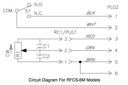
I want to build a foot pedal for my TIG welder. I am fairly capable with wiring and soldering, and I can do ok reading schematics when needed. The schematic provided by Miller in their manual though, doesn't show or reference any values for the components.
I'm wondering how I can best determine the value, in the absence of a working pedal.
I have attached the schematic they provide.
Through google searching, it looks like the potentiometer used is a 1k, 2 watt. I am not sure how to determine the values to use on the decoupling capacitors for C1 and C2.
Thanks for any help!

Tony Brenke
Oct 24, 2013, 11:19:56 PM10/24/13
to heatsy...@googlegroups.com
You can use .1uf caps for that. They are just used to take the noise ripples out that the pot makes
> --
> You received this message because you are subscribed to the Google Groups "HeatSync Labs" group.
> To unsubscribe from this group and stop receiving emails from it, send an email to heatsynclabs...@googlegroups.com.
> For more options, visit https://groups.google.com/groups/opt_out.

Kel
Oct 24, 2013, 11:41:36 PM10/24/13
to heatsy...@googlegroups.com
The caps are for noise reduction, but the pot is what is important. This conversation may help you out.....
http://weldingweb.com/showthread.php?7304-Difference-in-pedals
http://weldingweb.com/showthread.php?7304-Difference-in-pedals
Marc Dehoux
Oct 25, 2013, 1:10:14 AM10/25/13
to heatsy...@googlegroups.com
Outstanding! Would a certain capacitor be better than another for this type of application? Ceramic vs film vs etc?
Tony Brenke
Oct 26, 2013, 8:24:52 PM10/26/13
to heatsy...@googlegroups.com
for switches (5V low current) and trim pots the ceramic version is fine. your not doing anything exotic with this.
a tantalum cap will have a lower impedance but your rate of change and the ripple produced by this will be small anyway. wasted money for a tantalum.

Mike Bushroe
Oct 27, 2013, 10:12:44 PM10/27/13
to heatsy...@googlegroups.com
Mark, that is the exact same circuit diagram I saw Nate using to work on the Lab's TIG foot pedal. I seem to remember the DVM showing 10K on the pot at max, but it might also have been 5 K. You also need to be careful on which wire goes to the side of the pot that will be highest resistance when the foot pedal is up. I vaguely remember that it went on the reverse of what I expected, with highest resistance when the pedal is up going to brown (which looks from the wiring to be ground). But I could be wrong as it has been some time. I could not open the tread in the welding web forum, so I don't know if they answered all these points already.
I agree with the above that it appeared to all be low voltage stuff in the pedal. But I would still consider a bypass type cap for the circuit as the TIG probably induces a lot of EMF near it produce the constant current - variable voltage needed for adjusting the welding arc. But a ceramic 0.1 to 1.0 used to bypass digital chips on a circuit board provide the same function and should work well and are plentiful and cheap.
Mike
Reply all
Reply to author
Forward
0 new messages