robot dog

411 views
Skip to first unread message

James H Phelan

unread,
Sep 11, 2022, 11:47:07 AM9/11/22
to hbr >> HomeBrew Robotics Club, David Williams, Brown, Raymond & Diane, Will Dauchy, Han Ooi, Roberto Pensotti, Charles de Montaigu, Harsh Bhasin, Carroll Vance, Vesa Pykala, omar.herm...@gmail.com, Alan Holmquist, Heather Kaiser-Hahn, Usha Bhasin, Tom Atwood, ericde...@protonmail.com, Andrew Nobbay, Chuck Rousser, Avishek Roy Chowdhury, Derrick Morse, davi...@yahoo.com, Kevin Kin, Karl Schleicher, David Taylor, Sachit Bhasker, Sid Agarwala, Kywan Kerawalla, Gene Bremer, Anjan Mundlur, Kit Kennedy, Denzel Wilson, David Whitacre, Michael Solis, Donaldo Almazan, ho...@candiesolis.com, Tiffany Carcamo, Max, Michelle Nagler, Phelan, James H, Mara Hopewell
Team,

Stumbled upon this on Amazon.  Since I already have a Pi4 for the Rover,
decided to go for it!

https://www.amazon.com/gp/product/B08C254F73/ref=ppx_yo_dt_b_asin_title_o01_s00?ie=UTF8&psc=1
<https://www.amazon.com/gp/product/B08C254F73/ref=ppx_yo_dt_b_asin_title_o01_s00?ie=UTF8&psc=1>

Robodoc

--
James H Phelan
"Nihil est sine ratione cur potius sit quam non sit"
Leibniz

"Here am I, the servent of the Lord;
let it be with me, according to your Word"
Luke 1:38

Chris Albertson

unread,
Sep 11, 2022, 12:50:48 PM9/11/22
to hbrob...@googlegroups.com
I've been working on something like this, but larger.  I think I spent more on plastic for my printer and screws than their asking price.  I like that this robot comes with open-source Python code.

Could you give us a link to the Python code?  They say it is printed on the box.   I'd like to see how it works. 

--
You received this message because you are subscribed to the Google Groups "HomeBrew Robotics Club" group.
To unsubscribe from this group and stop receiving emails from it, send an email to hbrobotics+...@googlegroups.com.
To view this discussion on the web visit https://groups.google.com/d/msgid/hbrobotics/15f334e4-7b63-01c5-4fed-8ad034263572%40hal-pc.org.


--

Chris Albertson
Redondo Beach, California

Alan Downing

unread,
Sep 11, 2022, 3:41:49 PM9/11/22
to hbrob...@googlegroups.com
The code appears to be available via:


Sent from my iPhone

On Sep 11, 2022, at 9:50 AM, Chris Albertson <alberts...@gmail.com> wrote:


Dave Everett

unread,
Sep 11, 2022, 4:35:27 PM9/11/22
to hbrob...@googlegroups.com
I got a virus alert when unzipping the files. 


threat.jpg

Alan Downing

unread,
Sep 11, 2022, 5:41:34 PM9/11/22
to hbrob...@googlegroups.com
You can look at the online python files without cloning at:

https://github.com/Freenove/Freenove_Robot_Dog_Kit_for_Raspberry_Pi/tree/master/Code

Sent from my iPhone

On Sep 11, 2022, at 1:35 PM, Dave Everett <daveev...@gmail.com> wrote:


Mark Johnston

unread,
Sep 11, 2022, 6:22:28 PM9/11/22
to HomeBrew Robotics Club
What a howl!    Great find!   'Im In'  as well.
Thanks James!

Mark Johnston

unread,
Sep 11, 2022, 6:25:02 PM9/11/22
to HomeBrew Robotics Club
I'm glad it runs on the 3B as well, I have those comming out of my ... um ...  bench!    4B is a precious thing still and to get one is about the price of the robot kit!

James H Phelan

unread,
Sep 11, 2022, 7:24:59 PM9/11/22
to hbrob...@googlegroups.com

Mark,

Good catch!  I have a similar affliction with 3B's!

Robodoc

James H Phelan
"Nihil est sine ratione cur potius sit quam non sit"
Leibniz

"Here am I, the servent of the Lord;
let it be with me, according to your Word"
Luke 1:38

Chris Albertson

unread,
Sep 11, 2022, 7:26:53 PM9/11/22
to hbrob...@googlegroups.com
I have been reading the code, some observations

This robot uses the same chips I use in my robo-dog.  I am not surprised because every robo-dog I've seen that uses hobby servos uses the same chips in the controller, That would be the PCA9685 for generating the pulses and the MPU6050 as the IMU.   It seems that everyone who designs this uses the same solutions for the same reasons. 

Movement is done in (x,y,z) space and then inverse kinematics is applied using what textbooks call the "analytic technique" where you just use a bunch of trig functions in custom code.   Again just about everyone does this if the legs are 3-DOF or less.  

The step generation is hard to figure out.  In fact I don't see it (yet).   I'm beginning to suspect they don't bother to do this and use a different method.  Here is what I'm beginning to suspect:   For forward movement, they translate the body forward by moving the legs backward then as a leg gets too far back and crosses a limit it is instantly zipped back to a neutral position where it again starts to translate backward.

This is actually an easy and fully generalized method but can't be extended to non-flat floors.  The body moves by rotation and or translation as commanded from the GUI on the client system (windows, mac, Iphone,..) then as leg angles reach their limit they are reset to a standard neutral.  This one method then does spins, crab walking and even normal forward.     What I have not figured out is why all four legs don't get moved back at the same time.      But I could be totally wrong.     If someone figure it out please post.  But I can't see anything that looks like what I would call a "gait generator"

About the mechanical design.    It is completely conventional (but called down) as robo-dogs go. 
  I try to look at every one of them I can find.   This one is clearly optimized for low-cost and light weight.  Mine is optimized for very high strength and repeated assembly/disassembly. They are polar opposites but logically share the same  geometry.   This one on Amazon is going to "eat servos" as all the weight is on the output shafts with high bending loads on the shafts.   But it uses really cheap servos so you can afford to replace them.  I used $20 servos so I placed the loads on external ball bearings.  But my dog-bot might cost over $500 to build and this one is under $200.    Functionally they are quite a lot alike.  

If someone wants to take this robot as far as it can go. Try running the chvmp/champ software on it.  https://github.com/chvmp/champ 
This is a ROS based quadruped and is very sophisticated.  I think this cheap dog-bot could run this software.   With this you get the full SLAM and obstacle avoidance, Gazebo simulation, and everything else you'd expect.

Chris Albertson

unread,
Sep 11, 2022, 8:17:12 PM9/11/22
to hbrob...@googlegroups.com
I'm beginning to understand the software better.     I could not find a step generator on the robot because that is not how it works.

There are two parts 
(1) server that runs on the Raspberry Pi on the robot.  It gets commands from the client and 
(2) the client.  This can run on a Windows PC.  The client sends commands like "take one step forward" or sets the lean angle or the height of the body over the ground.

So to walk continuously the GUI must send a series of "take forward step" commands

This is how the robot is able to walk to a red ball.   The video data is sent to the PC and it runs openCV to find the ball and then sends step forward, or step left or other movement commands to the server.  The server reads commands then calls the function to do the command, then reads the next command.

So I was able to read and understand all the kinematics and how the PCA9685 and the IMU were used but was frustrated because there was no "cycle" that made it walk.    There is none.  The cycle is done on the PC.  The walk forward 8 steps it send 8 "forward" commands.   This is very flexible and greatly offloads the Pi.    No wonder any Pi can work.  The PC is doing the heavy lifting.

That said.   I bet $1 my software would work on this robot after a hour or so and even better the cvmp/champ ROS based stuff would work too.

One more idea, maybe the best...  The server runs as a Linux process on the Pi.  Write your own "client" that also runs on the same Pi and have it send "step forward" commands.  You can also run a voice recognizer in the Pi and have the robot do simple voice commands.  Or maybe just read from a game pad controller.


Mark Johnston

unread,
Sep 13, 2022, 2:56:50 AM9/13/22
to HomeBrew Robotics Club
Very helpful Chris and Alan.   Thank you for your insightful and informative comments.

I get my 'Fido' tomorrow.  I would be interested in something Chris has suggested which is form some scripts to do the commands to the on-board server for 'The Pooch'.    Sort of open loop but still it would allow standalone minimal operations.    

Thanks to others who have commented as well as James of course for another cool find.   Looking forward to a whole lot of fun!

James H Phelan

unread,
Sep 13, 2022, 11:12:21 PM9/13/22
to hbrob...@googlegroups.com

RoboBuds,

My "dog" arrived this evening & unboxed.  Nicely packaged and laid out.

Scanned the Tutorial.pdf and was VERY impressed with the detail, clarity, and examples throughout!

Looking forward to assembly and programming!

RoboDoc

James H Phelan
"Nihil est sine ratione cur potius sit quam non sit"
Leibniz

"Here am I, the servent of the Lord;
let it be with me, according to your Word"
Luke 1:38

Dave Everett

unread,
Sep 14, 2022, 1:24:48 AM9/14/22
to HomeBrew Robotics Club
On Monday, 12 September 2022 at 7:41:34 am UTC+10 Alan Downing wrote:
You can look at the online python files without cloning at:


Ahh yes but I couldn’t pass up the opportunity to buy yet another robot dog so I will need to run those files :)

Dave 

Mark Johnston

unread,
Sep 14, 2022, 3:42:42 AM9/14/22
to HomeBrew Robotics Club
Having completed all servo assemblies (about half way through the build).   I feel that the statement 'Some assembly required'  is a very safe and true statement.
The only part of all of it that was not so fun was removing all the dang paper that was on both sides of the (very nicely) laser cut parts.  They do include a little tool to help but it was almost easier to use fingernail to get a corner going then peal it away.   Again, THAT was anoying but the parts are shiny black and are very nicely cut.

The next step is getting the Pi to 'zero' all the servos then attach the servo assemblies.    Its quite a build but I must say, rather fun.

I agree with Chris when he said this thing will eat servos.   They are not beefy and are just the MG90S (ish) sort of servos.  When I run this thing I am going to be very careful to not let them overheat.  At least the servos have brass gears so that makes me feel a tiny bit better.

The last half of the build will be power up the Pi (I'm going with Pi 3B for now as my Pi 4 units ... 'They are precious to me'.   One Pi to rule them all!

With some luck I may have this puppy at least assembled with zeroed servos tonight (note the use of 'puppy'!)

Mark

Dave Everett

unread,
Sep 14, 2022, 3:57:36 AM9/14/22
to hbrob...@googlegroups.com
Good to hear of your progress. I'll be keen to see any changes you make to the walking. As with most robot dogs I've seen the legs seem way too far apart in the X axis, that is the 2 front legs are too far apart and the 2 rear legs similarly. It makes smooth walking impossible. I suspect I will redesign and cut the body to put them closer together. 

I have seen to date no real dogs with legs so far apart, I suspect because any examples failed to walk to a suitable mate to pass on their genes.

Dave

--
You received this message because you are subscribed to the Google Groups "HomeBrew Robotics Club" group.
To unsubscribe from this group and stop receiving emails from it, send an email to hbrobotics+...@googlegroups.com.

Chris Albertson

unread,
Sep 14, 2022, 12:28:18 PM9/14/22
to hbrob...@googlegroups.com
As an experiment, prior to rebuilding the chassis, a simpler approach is to modify the software to move the feet closer to the center.  Angle them in a little.  In the code supplied, they define a "neutral" stance and this would be easy to redefine.

I've experimented with walking with a wide and narrow stance.  In seems intuitive that a wider stance would be more stable.  It is until the robot tries to walk and lifts a foot.   If the stance is more narrow, then lifting a foot creates less imbalance.    The real problem is the servos are not precision devices and the feet on the ground don't have equal pressure and a narrow robot falls over.       There is an optimal width should I say a "least bad width" that you can find by experiment.   As said, the way the code works is by reference to a neutral stance that is defined by some constants.  Just change the constants.

The other thing I notice in their software is that the IMU is not used except when running the "balance trick".   It seems not to be used for normal walking.  So if the stance is very narrow keeping the feet under the "zero moment point" might be hard.    It is easy to keep the feet under the geometric center of mass on a flat floor, but if the robot moves, momentum matters.    But my experience is with my MUCH heavier and much taller robo-dog.    

My conclusion from experiment is that if the robot can actively balance then the best stance width would be what my real dog does.  She moves her feet inward as close as she can, maybe to half her shoulder width when at a fast trot.   But with no ability to actively balance (the IMU is of little use if using hoby servos) then you need a wide stance for better static stability.    The problem with servos is (1) They are slow to move, any balance correction has lag and (2) the positioning is imprecise.    Using BLDC motors and digital shaft encoders would be ideal, but they are 25 times more expensive.

For a given speed, the product of step-length times step-rate is constant.   So you get to choose a trade-off.   With no active balance, short steps "win" but it looks very unnatural.

I think you get the point.  Putting that IMU to work is very important for dog-like walking.  If you ignore the IMU you end up with very robot-like walking with short, fast steps and wide stance.

Look at the chvmp/champ software if you want a near state of the art dog-bot.  I'm trying to create a more flexible software in pure Python from scratch and it is slow-going.  This Amazon robotuses the same PCA9586 cip at the same I2C address as every other sevo-controlled dog-bot so software is somewter portable

Mark Johnston

unread,
Sep 15, 2022, 12:30:11 AM9/15/22
to HomeBrew Robotics Club
WARNING ON FIX FOR THE Servo.py that sets servos to 90 for proper assembly:

I found a couple bugs.  

1)  The print statements that were printing 90 for 90 deg (on two different lines) were failing so I just made them print 90 , plain and simple, no fancy trick for the 'degree' character

2)  The while for 16 servos needed a delay between servo settings or it bombs out of the script.

So make your __main__ look like this for the fixes I had to use for the script used to set servos to 90 so proper angles can be had on legs

if __name__ == '__main__':$
    print("Now servos will rotate to 90") $
    print("If they have already been at 90, nothing will be observed.")$
    print("Please keep the program running when installing the servos.")$
    print("After that, you can press ctrl-C to end the program.")$
    S=Servo()$
    while True:$
        try:$
            for i in range(16):$
                S.setServoAngle(i,90)$
                time.sleep(0.02)$
        except KeyboardInterrupt:$
            print ("\nEnd of program")$
            break

Chris Albertson

unread,
Sep 15, 2022, 12:51:38 AM9/15/22
to hbrob...@googlegroups.com
I think the problem is writing data too fast to the I2C interface.  Did you set the bit rate to 400,000?  (The default is 100,000.) If not, this is a big performance hit.

For a setup program, this is ok, but some improvements are
  1. Just write to the PSA9658 control registers once and set all PWM channels to 1000 uSec at the same time.  No need to loop over range(16)
  2. Why loop forever? The controller chip does not forget its settings until you kill the power.
But I'd not waste time on fixing something that works and is only a test/setup program.


Mark Johnston

unread,
Sep 15, 2022, 2:48:13 AM9/15/22
to HomeBrew Robotics Club
Status:   Robo-Pooch is fully assembled and all tests in the test.py all run from servos, sonar, camera, led, buzzer.

I am using a Pi3 B  with the Ubiquity Robotics most recent Kinetic image and it all works so far.   I did that so I can have ROS (I) completely present already and I am very used to that image.

Next will be to connect up this 'puppy'.

One more suggestion:   The head uses some M2 x 14mm screws.   They 'may' work but are too close for comfort for me so I attached the blue servo with some M2 x 12s I had in my stash.  

The build is done but cable dressing I may do next or wait till this pup does some more 'doggie-like' things.

To Chris:  Yes I set i2c 400000 clock.   I2C is working and sees the required 3 devices and does all the servos.    
Maybe it is really not at fast clock but I'm ok for now and don't want to get distracted.

Mark Johnston

unread,
Sep 15, 2022, 4:11:48 AM9/15/22
to HomeBrew Robotics Club
It was not bad to just make automated sequences in python starting from their   test.py script in the 'Servo' command execution.
Was with a little bit of sorting out direction of rotation vs what side of robot able to do simple push-ups on front legs.

This will be a ton of fun but I have to watch the servos and not burn them out.  That is my prime fear here.  They are 'whimpy'

Mark

Chris Albertson

unread,
Sep 15, 2022, 7:04:41 PM9/15/22
to hbrob...@googlegroups.com
If anyone wants, I can point you to some STL and CAD files.  My "dog" is literally plug-compatible with the Amazon robot.  (every servo powered dogbot seems to be a copy of every other servo powered dogbot)   Mine will cost you two spools of printer plastic and the cost of 12 of the best servos you can afford. plus $125 in stainless steel nuts  and bolts and ball bearings and some high grade batteries.   The robot I have is very robust.

But really, It would be easier to just buy a dozen spare 90g servos.  They are only $5 each.  This Amazon dogbot seems the ideal entry point for walking robots.   

I've been mining the software for good ideas.


Mark Johnston

unread,
Sep 16, 2022, 3:24:45 AM9/16/22
to HomeBrew Robotics Club
I will be now looking about for self contained 'walk a little ways'   or 'walk in a circle' sequences.  I am hoping there are some in the python scripts in their github.  Time to look!

This is a fun diversion to be sure!

Mark Johnston

unread,
Sep 16, 2022, 3:35:13 AM9/16/22
to HomeBrew Robotics Club
Ok, found great little sequences in Freenove_Robot_Dog_Kit_for_Raspberry_Pi/Code/Server   in   Action.py    Once you get going, check that module out.  
It seems RIPE for building upon!

Sampsa Ranta

unread,
Sep 16, 2022, 10:31:50 AM9/16/22
to hbrob...@googlegroups.com
I liked this toy fellows open dog.


In the videos he also explains the inverse kinematics and has open source code.

Not exactly same ecosystem stuff.

Enjoy,
 Sampsa

Chris Albertson

unread,
Sep 16, 2022, 1:26:19 PM9/16/22
to hbrob...@googlegroups.com
But it basically never worked well and he seems to have given up.  His problem was the size and weight of this robot and the inflexible software.  Don't under estimate the software.  Most robot dogs use very simple software and fixed leg motions,  These only work because there is human-in-the-loop control or they go for chvmp/champ.   Pretty much the two extremes.

One of my tasks, coming up, is to see if my robot can stand on two diagonal feet.  The feet are spherical balls so some balance is required.   I doubt it will work well with hobby servos but it will have to work "well enough" for realistic dog-like walking to work.

Mark Johnston

unread,
Sep 18, 2022, 10:02:01 PM9/18/22
to HomeBrew Robotics Club
Tips On RoboDog code fragments.

I had only one bad servo but am going to put in an order.  

I printed some much taller stand pieces so I can dry run things.  The stock ones are 80mm and good for 'training wheels' but do not fully isolate for your in-place tests.  I attach an STL if you want to print some taller stands.  

Here are some nice pieces to help other get going faster as I had to RTFS to find some/all of this.
Get into  Code/Server   as that is where the good stuff is located if you are going to try to make a self contained doggie (no windows PC embilical)

python test.py  <command>                     This is very first thing to run and instructions discuss this.  This at the end has the command interpriter and it a good 'back to test mode' tool

python Action.py                                         This has some more complex movements but no 'interpriter'  so go to end and uncomment the sequences you want to play with.

Control.py        This is mostly imported by other tools and has a great many really nice starter primitives' for movement

python myCode.py                                      This will go through many sequences and this is the 'gold'.   For your own stuff take a look at all the things it does at the end calling methods.

myCode.py  seems like a great tool to cut-paste out your own things that are perhaps done in a sequence you want as you develop your robot full standalone app.  It does not use all the interfaces in Control.py but does use   forWard()   and there is in Control.py many other primatives such as  backWard()   Control.py has the primatives but also a big case statement for all the CMD_ commands.
so Control.py methods will be invaluable to make your doggie do things like walk around in some pattern or smething you want .
Later Control.py will be valuable so you sense things and then do different movements on how you want doggie to do stuff from external inputs.

Now it's time for some fun!

Mark
RobodogStand.stl

James H Phelan

unread,
Sep 18, 2022, 10:24:00 PM9/18/22
to hbrob...@googlegroups.com

Mark,

Just tonight got mine to the point of fully assembled, up on calibration stand and calibrated the best I could.

Looks like one servo isn't responding at all and another is slow and stiff.

I replaced the unresponsive one with a spare in the kit but will have to wait til tomorrow to re-calibrate.

What do you recommend for replacement servos?  Got a link?

Would like a stand that would be easy to mount and dismount instead of 4 bolts with hard to reach nuts.

Will have a look at yours.

Explored the iPhone app, pretty good.

RoboDoc

James H Phelan
"Nihil est sine ratione cur potius sit quam non sit"
Leibniz

"Here am I, the servent of the Lord;
let it be with me, according to your Word"
Luke 1:38

Mark Johnston

unread,
Sep 18, 2022, 11:14:57 PM9/18/22
to HomeBrew Robotics Club
Servos:  I started reaching for my box of 9g style servos.  Here is what I have found:  I have none of my favorites as a 'match'

They use a brass head (and hopefully metal gear inside is my guess) 9g sort of servo but I have not measured if they are 9g or beefier.
Main trouble is these servos use a 15 tooth main gear that is 3.9 mm across and are totally void of any label.

My fav metal gear one is  the MG90S but it is aluminum gear of 20 teeth and 4.8mm across so total non-fit.
Then I started looking at my plastic gear ones like Tower Pro  Micro Server SG90. It is at least 20 teeth and about 4.8mm dia so it was also no-go.

I am joining a facebook 'Freenove Robot User group'  but cannot post yet till I am 'in'.  I have been browsing for type of servo, no joy yet.

On the mount easily, yes, I get that it would be nice for push-pull pin to mount those, have not done that 'yet'.  Screws are a PITA for this sort of stand to swap them.

I'll know more after more research

Mark

Dave Everett

unread,
Sep 18, 2022, 11:19:24 PM9/18/22
to hbrob...@googlegroups.com
My dog has apparently arrived. I won't pick it up until tomorrow night. I have already been thinking about redesigning the laser cut parts if need be, and using different servos. I will post a link if I redesign to use better servos.

I also found they do an ESP32 version, so of course I bought that as well.

Dave

Mark Johnston

unread,
Sep 18, 2022, 11:55:52 PM9/18/22
to HomeBrew Robotics Club
Found these servos as candidates and am going  get some on amazon as they would be of use for other servo needs anyway.  
All my servos are ok with only 1 was bad but note somebody else also has 2 servos DOA.   So count on some servos going to servo heaven (or hell ... not sure)
These servos they ship rotate 90 deg with near 10% duty cycle change (roughly measured today)

Anyway, what I found look like 15 tooth brass gear and are 12G so this would make perfect sense a bit more beef than the 9g models AND even internal gears look brass. 
Link below has a bit of a spec for the ones I am buying but I do not have a spec for what is really in the dog ... still looking for that.


Also: Yes, I saw they were doing an Esp32

Also the facebook group I discussed is mostly on the hexapod


Mark Johnston

unread,
Sep 20, 2022, 5:09:06 AM9/20/22
to HomeBrew Robotics Club
Now have integrated one of these little tiny car RC controls I used on Fiddlerbot and other robots for simple movement prior to bluetooth gatt server and other more complex web interfaces.   

So I have forward, reverse, rotate right and rotate left all working.

Next I decided to make with my resin printer little 3mm pins to hold the two style stands.  One set of stands is for normal walking and prevents pooch from full collapse to ground.  The other stand I posted stl for earlier and that is so all legs move however you like but bot does not touch ground.

So now I attach a screenshot from OpenSCAD both to show this push pin design and to get people to like OpenSCAD.  This is a great design to hold parts together for quick release, do not let your mind wander and consider it's  'rude' shape.  It pushes into the 2 layers of 3mm holes and snugly holds them then simply pull out to put on other legs or leave legs off (if you are confident in all your code!)

Mark

PushPinForStandQuickRelease.jpg

Mark Johnston

unread,
Sep 20, 2022, 9:59:33 PM9/20/22
to HomeBrew Robotics Club
Well forget about that push pin, it seemed a nice idea but due to stresses of a rather heavy robot dog above it they are not as strong at all as a nice metal screw.  So scratch that pin!

Next: I now got today 12g servos that look identical to what is required.    Have not tried one yet but seems very good.   I'll try a 'knee' tonight. 
They are the link earlier posted:    https://www.amazon.com/gp/product/B07RRWYXL9/ref=ppx_yo_dt_b_asin_title_o00_s00?ie=UTF8&psc=1

Also I fully got my RoboDoggie to now have interface board for this RF controller I have used many time and I can go  'forward, reverse, right, left'  and it all fully starts up from power-on so it is in a crude way fully standalone and operational!      A Milestone for my goals so far. 

I will show this thing at the hbrc meeting on 28th is the plan, hopefully with some modest ROS integration which is doable if all goes well.

Now it's off to try to make 'rubber boots' for the feet because the hard Acrylic feet slip too much.    I will make feet using 3d printed PolyFlex or maybe NinjaFlex, both of which are 'rubber-like'.

Take Care you Scurvy Dawgs!    (yesterday was ITLAP day, International Talk Like A Pirate Day)
Mark


Mark Johnston

unread,
Sep 21, 2022, 9:39:21 PM9/21/22
to HomeBrew Robotics Club
Did 'Knee Surgery' using the E-Max 12g servo.  Physical match is exact where the brass gear with 15 teeth was crucial to have proper size and teeth count.   I read one report on the facebook group where some guy managed to get the MG90S to work but those have wrong outer diameter for the metal gear and 21 teeth or maybe 20.  Point is they don't work at all so the guy drilled out things and so on.   Lol.  We know better!

So it functions in the place of a Knee servo and I bet is fine in all leg positions.  This prompts me to rig up a little lever thing to test these for ballpark stall current but perhaps another day.    I am 98.345 % sure these are a perfect replacement.  (notice the precision of my calculation!)   

Next I have to work out the calibrations for each servo with their gui based tool.  With such a coarse servo tooth of about 24 deg per tooth that calibration will be key to get the doggie standing nice and 'lookin good'.  

Marco Walther

unread,
Sep 21, 2022, 10:46:51 PM9/21/22
to hbrob...@googlegroups.com, Mark Johnston
On 9/21/22 18:39, Mark Johnston wrote:
> Did 'Knee Surgery' using the E-Max 12g servo.  Physical match is exact
> where the brass gear with 15 teeth was crucial to have proper size and
> teeth count.   I read one report on the facebook group where some guy
> managed to get the MG90S to work but those have wrong outer diameter for
> the metal gear and 21 teeth or maybe 20.  Point is they don't work at
> all so the guy drilled out things and so on.   Lol.  We know better!

Look at the attached screen grab of their video on Amazon;-) Those
servos have labels;-) And from what I've seen, they look a lot like the
ones, you found;-)

Hope, this helps;-)
-- Marco
> Main trouble is *these servos use a 15 tooth main
> gear that is 3.9 mm across and are totally void of
> any label.*
>> 1. Just write
>> to the
>> PSA9658
>> control
>> registers once
>> and set
>> all PWM
>> channels to 1000
>> uSec at
>> the same
>> time. No
>> need to
>> loop over
>> range(16)
>> 2. Why loop
>> *1)  The
>> print
>> statements
>> that were
>> printing
>> 90 for 90
>> deg (on
>> two
>> different
>> lines)
>> were
>> failing so
>> I just
>> made them
>> print 90 ,
>> plain and
>> simple, no
>> fancy
>> trick for
>> the
>> 'degree'
>> character*
>> *
>> *
>> *2)  The
>> while for
>> 16 servos
>> needed a
>> delay
>> between
>> servo
>> settings
>> or it
>> bombs out
>> of the
>> script*.
>> <https://github.com/chvmp/champ>
>> <https://groups.google.com/d/msgid/hbrobotics/732e6b07-d270-43cc-9bdd-789cfc95e1e6n%40googlegroups.com?utm_medium=email&utm_source=footer>.
>> https://groups.google.com/d/msgid/hbrobotics/CAG61pbeKB3X69UkzbmwayHHVaTd%3Dt-HEk1wzQSqHuyjr_nWvPg%40mail.gmail.com
>> <https://groups.google.com/d/msgid/hbrobotics/CAG61pbeKB3X69UkzbmwayHHVaTd%3Dt-HEk1wzQSqHuyjr_nWvPg%40mail.gmail.com?utm_medium=email&utm_source=footer>.
>> <https://groups.google.com/d/msgid/hbrobotics/1c8c4e21-a6cd-4bdf-997f-3c4a18bd8896n%40googlegroups.com?utm_medium=email&utm_source=footer>.
>>
>>
>>
>> --
>>
>> Chris Albertson
>> Redondo Beach,
>> California
>>
>> --
>> You received this
>> message because you
>> are subscribed to the
>> Google Groups
>> "HomeBrew Robotics
>> Club" group.
>> To unsubscribe from
>> this group and stop
>> receiving emails from
>> it, send an email to
>> hbrobotics+...@googlegroups.com.
>>
>> To view this
>> discussion on the web
>> visit
>> https://groups.google.com/d/msgid/hbrobotics/c838eacf-62f5-430e-9718-ae0dc425a944n%40googlegroups.com
>> <https://groups.google.com/d/msgid/hbrobotics/c838eacf-62f5-430e-9718-ae0dc425a944n%40googlegroups.com?utm_medium=email&utm_source=footer>.
>>
>>
>>
>> --
>>
>> Chris Albertson
>> Redondo Beach, California
>>
>> --
>> You received this message because
>> you are subscribed to the Google
>> Groups "HomeBrew Robotics Club" group.
>> To unsubscribe from this group and
>> stop receiving emails from it,
>> send an email to
>> hbrobotics+...@googlegroups.com.
>> To view this discussion on the web
>> visit
>> https://groups.google.com/d/msgid/hbrobotics/18476bdb-5f38-40f5-9c37-20b618814764n%40googlegroups.com
>> <https://groups.google.com/d/msgid/hbrobotics/18476bdb-5f38-40f5-9c37-20b618814764n%40googlegroups.com?utm_medium=email&utm_source=footer>.
>>
>> --
>> You received this message because you
>> are subscribed to the Google Groups
>> "HomeBrew Robotics Club" group.
>> To unsubscribe from this group and
>> stop receiving emails from it, send an
>> email to hbrobotics+...@googlegroups.com.
>>
>> To view this discussion on the web
>> visit
>> https://groups.google.com/d/msgid/hbrobotics/CAOF2Wg4uFxMn0VSpNCn71j%3D_KN8g6wiBcJdJhtm4tw26c0SXPg%40mail.gmail.com
>> <https://groups.google.com/d/msgid/hbrobotics/CAOF2Wg4uFxMn0VSpNCn71j%3D_KN8g6wiBcJdJhtm4tw26c0SXPg%40mail.gmail.com?utm_medium=email&utm_source=footer>.
>>
>>
>>
>> --
>>
>> Chris Albertson
>> Redondo Beach, California
>>
>> --
>> You received this message because you are
>> subscribed to the Google Groups "HomeBrew
>> Robotics Club" group.
>> To unsubscribe from this group and stop
>> receiving emails from it, send an email to
>> hbrobotics+...@googlegroups.com.
>> To view this discussion on the web visit
>> https://groups.google.com/d/msgid/hbrobotics/1ade8739-b869-45bc-9176-c3598caf96a6n%40googlegroups.com
>> <https://groups.google.com/d/msgid/hbrobotics/1ade8739-b869-45bc-9176-c3598caf96a6n%40googlegroups.com?utm_medium=email&utm_source=footer>.
>
> --
> You received this message because you are subscribed
> to the Google Groups "HomeBrew Robotics Club" group.
> To unsubscribe from this group and stop receiving
> emails from it, send an email to
> hbrobotics+...@googlegroups.com.
>
> To view this discussion on the web visit
> https://groups.google.com/d/msgid/hbrobotics/6aabf8b3-628f-4bc1-9717-ad2d8875d349n%40googlegroups.com
> <https://groups.google.com/d/msgid/hbrobotics/6aabf8b3-628f-4bc1-9717-ad2d8875d349n%40googlegroups.com?utm_medium=email&utm_source=footer>.
>
> --
> You received this message because you are subscribed to the Google
> Groups "HomeBrew Robotics Club" group.
> To unsubscribe from this group and stop receiving emails from it, send
> an email to hbrobotics+...@googlegroups.com
> <mailto:hbrobotics+...@googlegroups.com>.
> To view this discussion on the web visit
> https://groups.google.com/d/msgid/hbrobotics/4d3a9b8a-d338-4730-9d67-5c283ab5b8a9n%40googlegroups.com
> <https://groups.google.com/d/msgid/hbrobotics/4d3a9b8a-d338-4730-9d67-5c283ab5b8a9n%40googlegroups.com?utm_medium=email&utm_source=footer>.
screen.png

Mark Johnston

unread,
Sep 21, 2022, 11:33:10 PM9/21/22
to HomeBrew Robotics Club
Yes, I found that even at the very top picture of that facebook group and found they were same in an 'unboxing video' somebody had on youtube.

This was factored into my 'precise'   98.345 %   level of certainty.  ;-)      (Discounted from 100% as only death and taxes are 100% certain)

Chris Albertson

unread,
Sep 23, 2022, 10:34:41 PM9/23/22
to hbrob...@googlegroups.com
Has anyone thought about how they would control a quadruped "dog-bot" using a game pad?  It is easy enough to handle events from the gamepad, but what I mean is how should the controls work?   For a simple differential-drive car a single joystick controls forward and reverse and rate of turn.  And that is all that a simple two-wheel robot can do.

But the dog seems like it can do more things than there are buttons on the controller.  While standing still, with all feet stationary, it can:
  • translate its body in all three directions (x, y, z)
  • rotate its body in three directions (roll pitch and yaw)
  • modify its stance (width of the legs and length in fore/aft direction)
Then, in addition  while walking it could also
  • Make turns where the robot walks in the direction its head faces
  • walk in other directions the head is not facing
  • rotate in place by shuffling feet.  Note that the center of rotation need not be directly under the robot's mid point.
  • Pick up the feet higher.
  • trade faster the longer steps to go the same speed. (step length vs step frequency)
  • change gait from creep to trot or others.
Then there are poses, like lay down, sit up and "whatever"  And then movements like "kick a ball" and eventually climbing a stair step

So far I have an X11 based interface using a mouse and a set of sliders.  While the robot can do 9 motions all at the same time.  I can only change one parameter at a time with my mouse.

I'm going to have to do something as controlling all this with a mouse is awkward.     Anyone have ideas on how a dog-bot hand controller should operate?

A J

unread,
Sep 24, 2022, 10:21:45 PM9/24/22
to HomeBrew Robotics Club
I have only used the microsoft controller with the quad copter in ros.

But that only has yaw, roll and pitch compared to a multi-legged robot.

I suspect that a higher level abstraction is easier because there many

patterns of walking and running.


Chris Albertson

unread,
Sep 24, 2022, 11:32:18 PM9/24/22
to hbrob...@googlegroups.com
This is my thinking too now.  A lot of the robo-dog is going to have to run on autopilot.  But I need to gain some experience driving by hand to know how to program the autopilot.

This means I'll control some things and the others will have to be computed.

The best solution would be a custom controller box but I don't want to take the time to build one.  I thought of using a MIDI control surface like the link below.  It has 16 analog controls and about 3 dozen buttons for $80. It is a USB device, and every OS now has MIDI drivers already installed.

I'd like it to be self-driving but it will take lots of experiments to figure out the best ways to move.   

My worst problem is the servos, they get sloppy quickly as the metal gears wear in.


--
You received this message because you are subscribed to the Google Groups "HomeBrew Robotics Club" group.
To unsubscribe from this group and stop receiving emails from it, send an email to hbrobotics+...@googlegroups.com.

James H Phelan

unread,
Sep 25, 2022, 10:53:48 AM9/25/22
to hbrob...@googlegroups.com, Roberto Pensotti
Robobuds,

After assembly discovered that some of the servos weren't responding.

Roberto loaned me a servo tester and a handful of identical replacement
servos he had from Freenove.

I'll have to ask Freenove for some replacements.  They've been
responsive so far.

Replaced 2 servos and was able to calibrate FIDO and take it for a
successful short walk before it demanded a rest.

It's not as graceful as Spot, but at $130 vs $74,500 I'm satisfied.

I'd like to try some of the other software mentioned previously in this
thread.

I tried not bolting the calibration supports to the dog but instead just
fixing the screws to the supports then poking them into the dog.  Worked
good enough and easy to remove.

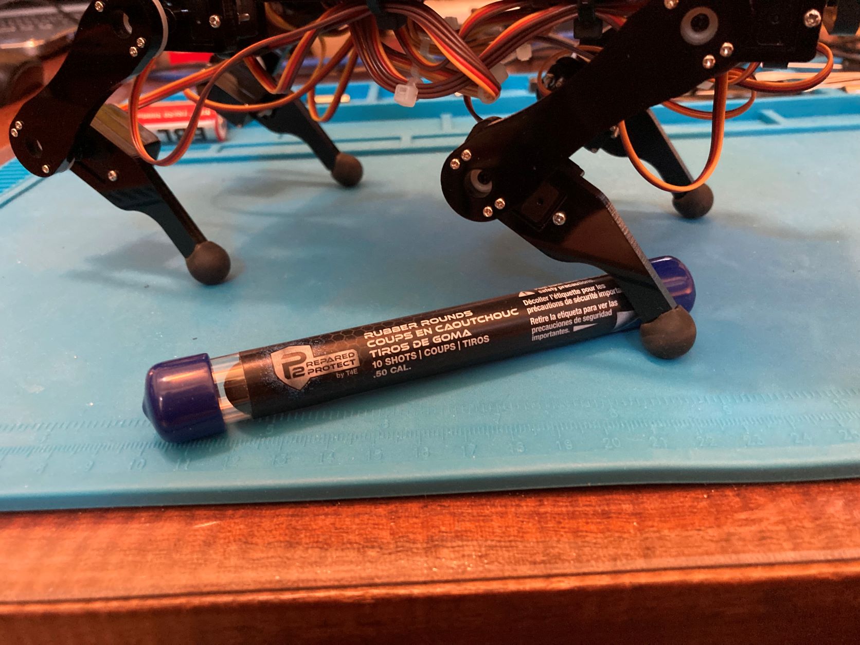
Would like to find some rubber ball feet for traction.  Perhaps these:

https://www.amazon.com/Umarex-Paintball-Count-50-Caliber-Rubber/dp/B08J62CBW7/ref=sr_1_1?keywords=50%2Bcal%2Brubber%2Bballs&qid=1664116112&sprefix=%2C50%2Bcal%2Bru%2Caps%2C302&sr=8-1&th=1&psc=1
<https://www.amazon.com/Umarex-Paintball-Count-50-Caliber-Rubber/dp/B08J62CBW7/ref=sr_1_1?keywords=50%2Bcal%2Brubber%2Bballs&qid=1664116112&sprefix=%2C50%2Bcal%2Bru%2Caps%2C302&sr=8-1&th=1&psc=1>
Unbox 12 post calibration.JPG

Chris Albertson

unread,
Sep 25, 2022, 3:55:02 PM9/25/22
to hbrob...@googlegroups.com
That is my current project, making rubber feet for my dog-bot.

What I did and I'd suggest it, is to make some improvised feet first with foam and tape.  Figure out how big and how squishy or hard they need to by using whatever foam and tape and rubber bits you have around.

I plan to 3D print the feet from TPU.  I can control the stiffness by setting the infill percent, adjusting the skin thickness and making the tread pattern more of less deep

These will be the first generation feet.  The second generation will have pressure sensors.  Foot pressure is really need if you ever want to walk on not-flat paths. The robot moves its foot down until it "feels" something like 1/2 the robot's body weight on the foot.    The robot can also have a sense of balance by adjusting its stance so the weight on each foot is the same.

You can buy resistive pressure sensors for about $10.  They change resistance with pressure and come in all different sizes and shapes.

In any case, try "gaffer tape" or even white cloth "sports tape" or bits of bicycle inner tube superglued to the feet. and then you get a better sense of what kind of ball to look for.     

So people have used silicone seal window caulking for feet.  This can actually look really good if you 3d print a mold (prep the mold with some car wax to help release.)

--
You received this message because you are subscribed to the Google Groups "HomeBrew Robotics Club" group.
To unsubscribe from this group and stop receiving emails from it, send an email to hbrobotics+...@googlegroups.com.

Mark Johnston

unread,
Sep 26, 2022, 1:52:14 AM9/26/22
to HomeBrew Robotics Club
Have been away on a 3-night deep sky astronomy star party.    Back on this now but time is tight for Wed.

James: I really think the ES08MA II 12g Mini Metal Gear Analog Servo is completely fine and perhaps exact replacement.
Do NOT use other gear teeth.  It is not as simple as 'drilling out'.  You really gotta match all those gears or you are in for a nightmare of flakey mechanical issues.

Chris:  I at this time use a simple RF DIYhack for forward, reverse, right, left.    My goal next but likely AFTER this HBRC meeting is to use the joystick node and use a joystick.  It will always be non-precise and just hand operated but I would use Logitech or even X-box joystick with RF dongle.     

Feet:   I have now a 3D 'boot' and the disclaimer is this is first one that 'fits'.   It may not be optimal.  This has a flat side so it can be printed on an FDM printer using 'rubbery' stuff where I use   PolyFlex and will do some in softer NinjaFlex if required.     To print these soft FDM materials is an acquired 'art'.    Too deep to try to explain it here but I offer STL if you have a nice process already worked out.    My 'push goal' is to bring some to the HBRC meeting but it is not a 'promise'.  Plenty of room to improve on this but its going to be better (Higher static coefficient of friction) than hard feet the robot uses from laser cut acrylic.

Mark

RobodogFeet.stl

James H Phelan

unread,
Sep 26, 2022, 6:59:13 AM9/26/22
to hbrob...@googlegroups.com

Mark:

< Do NOT use other gear teeth.  It is not as simple as 'drilling out'.  You really gotta match all those gears or you are in for a nightmare of flakey mechanical issues. >

Pardon my ignorance but I don't see why.

There is an exact replacement so the question is moot but - assuming

1) the body of the new (20 tooth) servo is an exact fit

2) all the servos are replaced, not just some (although just opposite pairs might work?)

3) the servo teeth don't interact with any other gears, just their own servo horn, which is true.

The issue is whether the new servo horn could be made to fit where the old one was which might require new screw mounting holes.

The greater number of teeth might even make mechanical centering of the joints a little more (20/15ths) precise?

Mark Johnston

unread,
Sep 26, 2022, 8:35:01 PM9/26/22
to HomeBrew Robotics Club
On 20 tooth servos:    When you said drilling out I thought you meant the existing horns.  To replace all servos and all horns is of course okd.  It of course would be a a massive undertaking.   If you replace all the mating servo horns, sure.  But wow,  nasty bit of rework effort.

I think I lost track of why this is a good thing.   Maybe because the 20 tooth ones have much better stall torque or reliability?  Those would be the only reason to think about such an effort or perhaps other reason.

This may be a good 'segway' into something I must still do.   I thought there was some sort of 'soft' cal where each servo had in a .txt file some sort of pwm offset and scaling and there was this gui I saw with lots of controls.   I thought there was something to put soft servo cal data in a file for their drivers to use.    So far I have thought this was in the gui of the 'client' in some way that is seen on page 97 of the turorial.

In the turorial on Step 15 of their stuff called 'Verify Assembly' is what I would call a rough 'physical' alignment, NOT a 'soft calibration'.

If there is no soft calibration then I could also see the need for finer teeth than 15.

Anybody read enough to find and do the  'soft cal' if it exists is documented?    I'm a bit tight for time so 'throw me a bone' if ya got one.   

Thanks,   mark


Mark Johnston

unread,
Sep 26, 2022, 8:49:16 PM9/26/22
to HomeBrew Robotics Club
Boots:  In other news I have printed some boots in PolyFlex.   They are a bit of an improvement but still slip.
I may do them in NinjaFlex which is the softest stuff I have.  I had to play with the size to have nice snug fit.

So I attach now a 'better' fit for the boot.  I rushed the last one for a post, this one is nicer fit.
RobodogBoot.stl
RobodogBoot.scad

Chris Albertson

unread,
Sep 26, 2022, 10:20:04 PM9/26/22
to hbrob...@googlegroups.com
This does have to do with both servo calibration and "boots".  You can never get the servos calibrated 100% and this means that even on a level hardwood floor foot pressure will be uneven and it will change randomly.  Some feet will have weight on them and one might even be in the air.  The dog is directionally unstable.  It seems to turn based on which ever foot happens to have to most friction.  Flexible feet help.

Do watch the dimensions of the feet.  They add length to the lower leg and mess of the inverse kinematics,  You might have to measure and adjust constants in the code.

I think I found a way to steer a robodog.  I got this working today.   At first I tried "tractor turns" where to turn left, the right legs take longer steps and the left legs take shorter steps.   This fails badly as it requires controlled sliding and which feet slip is random.

Then got this to work.  To turn left, each front leg when it moves forward to take a step moves also a little to the left and then as it moves back, it moves back to the neutral position.  The rear legs  step to the right.  This way the body rotates as it walks.  The exact details depend on some trigonometry.   But it roughly works.  I command a 0.1 radian per second turn and the robot turns very roughly 0.1 radians per second to the left.

I can also now do roll, pitch and yaw rotations and x,y,z translations with stationary feet and also while walking.  The software takes the rotation, translation, and gait and turning inputs and adds them together.  Then computers the servo angles,  writes to the controller chip then does it again, 20 times per second.

One more thing, I found my gait generator is not generalizable to curved walking paths.  It assumes the feet move in straight lines when looked at from above.  This is not true when walking around a corner.  There is always more to do.

I'm controlling it all from an iPad now and this works well enough that I may postpone using the gamepad.   No fancy ISO app, just an X11 GUI running on the robot, exported to the iPad screen.

--
You received this message because you are subscribed to the Google Groups "HomeBrew Robotics Club" group.
To unsubscribe from this group and stop receiving emails from it, send an email to hbrobotics+...@googlegroups.com.

Mark Johnston

unread,
Sep 27, 2022, 12:15:38 AM9/27/22
to HomeBrew Robotics Club
My goal is not to make this thing navigate well.   I will get around to responding to visual input so if feet slip it means keep doing it.

It is more a curiosity with a cheap-o  toy-like doggie like this one.  

The calibration I am seeking is for the legs (which use 3 servos each) to be 'about' in the same position when the code tells them to all go to some hip, upper leg and lower leg joint angles.     Now I have some that are clearly off by quite a bit but less than one of the 15 gear teeth which is a very bad 24 deg per tooth.

Chris Albertson

unread,
Sep 27, 2022, 12:53:56 AM9/27/22
to hbrob...@googlegroups.com
They will never navigate well by open loop.   I was only driving by remote control.  So when the user presses the control left, what should the robot do? There are a dozen ways to steer a quadruped.   With no user input the robot rotated 90 degree left after walking 5 feet.   So I tried tractor turns and it only made it worse and more random.   It turned out what worked was rotating the robot on the z-axis while it was walking.

At this point I have very low requirements.  All it should do is follow the remote control.  I'd like it to go from living room to kitchen and back while I control it with my thumbs on the controls.

Once the remote control is working, then I'll put a camera on it


Mark Johnston

unread,
Sep 27, 2022, 4:36:22 AM9/27/22
to hbrob...@googlegroups.com
Yes.   Same goal.  The human is the 'navigator'.   That is 'Phase 1'.   
While Phase 1 happens start to hook up ROS interfaces for sonars and camera.
When I get my nifty ArduCam TOF gizmo in Nov, play with that OR I may just put that gizmo on Droidbot that has a chance at navigation.
Robo Doggie may just use camera then send it back on Rviz.     Just feedback to Rviz for sonars and camera for a while for Robo Doggie.

If I set my expectations low for El Cheapo Robo Doggie I will likely not be 'very' disappointed!   Lol

Mark Johnston

unread,
Sep 27, 2022, 9:10:48 PM9/27/22
to HomeBrew Robotics Club
Forgive me if this was in this thread but to repeat or offer this fresh here is the type of calibration I wanted and yes it is part of that gui.

https://www.youtube.com/watch?v=l2v9PdwQdvY

The sheet of paper has a great usage after all.  The sheet came with the doggie.     Off to get this going now.   

Mark Johnston

unread,
Sep 28, 2022, 2:09:32 AM9/28/22
to HomeBrew Robotics Club
Did the calibration with stands and gui.   Had to have GUI on the main.py code on the Pi which IMHO was a pointless gui and it would have been lower 'baggage' if I could start python tool main.py from a ssh console screen.  But I dorked around and got it running.

Sure enough, the cal data is saved to Code/Server/point.txt which is a flat ASCII tab separated file VERY easy to manually tweek too!
This is the cal I wanted so now my own app from my RF controller has the RoboDoggie standing nicely.

My polyflex boots work but I want even more grab so am now trying this with NinjaFlex which is the softest material I dare print at Shore hardness 85A which is 8-10 softer on the Shore scale of A (the softest scale).  

Chris Albertson

unread,
Sep 28, 2022, 2:27:01 PM9/28/22
to hbrob...@googlegroups.com
To make softer feet, use less infill percent and thinner wall.  Solid ninjaflex is actually pretty tough stuff,  But the same stuff mixed as 20% ninja and 80% air is softer.   I think a tread pattern in the bottom also helps, like knobby tires.  I find that even with well calibrated servos there is always one shorter leg so what is needed is compliance.  

But my "dog" weights in at about 10 pounds with larger feet so there is plenty room for detail design of the feet.  Mybe you don't have room for these details in the tiny feet?

I've decided to start thinking about "software version 2".  The current software is gathering many special cases and "if/then" checks. I think I can generalize it.   The method described below uses some ROS specif language, but need not use ROS.  So here is a description of "V 2.0"

The quadruped base controller subscribes to two input messages

1) Cmd_Vel, for "twist" messages.  The following fields are populated, X_Velocity, Y_velocity and Z_rotation.  These define the path over ground of the robot's "neutral center point" which is the center of mass when standing "straight".  This is not much different from a simple differential drive robot except motion can be in any direction, not just forward.

2) Cmd_Pose,  This in turn has two parts (a) translation in (x,y,z) and (b) an orientation quaternion (like roll, pitch and yaw.)   This tells the robot how to move the body relative to the neutral stance

By using the above we can have the robot crab-walking East while facing North and then send a cmd_pose to have it yaw left by 15 degrees while continuing to walk East.   It would twist its legs up by the 15 degrees and keep walking sideways.

The controller algorithm is conceptually simple.  It generates leg motions to execute the Cmd_Vel motion and it generates leg angles to execute the Cmd_Pose, then literally adds those two together

Next it checks balance limits by calculating the support polygon and the Zero Moment Point (ZMP, is like the center of gravity but also considers acceleration of the object in addition to the acceleration of gravity) and limits leg position so the ZMP pass through the support polygon.

Robot leg motion is simple too.  The leg lifts and then moves through the air at (say) 4x the robot's commanded velocity over ground and then moves to ground contact and then moves at exactly -1 times the robot's commanded velocity.  The exact path is done with splines or Bezier curves.

I think this is it.   My guess is that the above algorithm is 100% generalized and can control any action the robot can physically perform.   And it does this without treating yaws, body-rolls and crabwalks as special cases.   There is only one case, not dozens.

Next steps.   (1) Post this for comment in a few places and let people find any faults. (2) re-write it for clarity and add details (3) write some prototype code and run it on a PC.  (4) write the real code on the robot

I see no good reason this can't run on the small "micro-size" bots you all are buying from Amazon.    


Mark Johnston

unread,
Sep 30, 2022, 9:07:38 PM9/30/22
to HomeBrew Robotics Club
HBRC meeting followup:    Jim asked about the python raspberry Pi background monitor I used on RoboDoggie and have used in the past.

The start of the file will explain it in fair detail and I use it on many project both to auto-start things (even full ROS) or just python like for RoboDoggie.

https://github.com/mjstn/MarkWorldCodeModules/tree/master/RaspberryPiUtilities     Look at file sys_monitor.py

It is very flexible but with flexibility comes complications.  Assorted ways it run are done with files in  config/bin and also for it looking for specially named files to exist and if it finds them it will operate differently.    It is all explained in the start of the file.

Enjoy this script, another freebe from Mark-Toys.com!

Mark

James H Phelan

unread,
Oct 6, 2022, 5:27:17 PM10/6/22
to hbrob...@googlegroups.com

RoboBuds,

I got these from Amazon, drilled 1/2 way in with 1/4" bit then shoved them onto the feet.

Come 10/pkg

Seem to work good enough.

https://www.amazon.com/dp/B08J62CBW7?ref=ppx_yo2ov_dt_b_product_details&th=1&psc=1

Stephen Williams

unread,
Oct 6, 2022, 7:10:43 PM10/6/22
to hbrob...@googlegroups.com

Cool, thanks!

Stephen

--
You received this message because you are subscribed to the Google Groups "HomeBrew Robotics Club" group.
To unsubscribe from this group and stop receiving emails from it, send an email to hbrobotics+...@googlegroups.com.

Mark Johnston

unread,
Oct 9, 2022, 1:51:45 AM10/9/22
to HomeBrew Robotics Club
James:  Confirmation here on use of the paintball ammo for feet.    They even look nicer than may printed ones.

They are a touch better in performance than my NinjaFlex printed boots and are certainly required over the hard plastic feet as shipped with the kit.

I think there is HUGE room for improvement in the walking code they are using.   I'm going to put some effort in that as my RoboDoggie is a joke as far as how it walks.   Perhaps just slower movements may help a lot as it moves so darn fast it cannot keep traction.  Also it hardly pulls feet off the ground.

Chris Albertson

unread,
Oct 9, 2022, 2:39:21 AM10/9/22
to hbrob...@googlegroups.com
With quadrupeds that can't balance, there is an advantage to using a quick step.  If you raise two feet and wait, the robot falls down.  But if you pick the feet up and very quickly put them back down, the robot does not have time to fall.  Walking slowly is harder than walking fast.   There is also a best step height, that would be high enough and no higher.   

The real solution is to track the center of balance and keep it over the support polygon.   A walking root is not much different from a two wheel "balance bot". 

One experiment I want to do is have the robot lift a pair of diagonal feet and balance on the other two for as long as possible.  Then the robot should be able to translat along the line that connects the two feet that are on the ground.   I doubt this can work perfectly are servo lack performance.   Getting this to work "good as possible" is a first step to dynamically balanced walking

My latest success is what I call "fully generalized walk motion.  It can walk sideways, forward and back, and can spin all at the same time while also applying roll, pitch and yaw and X, Y translations to the body.   I think I will also be able to spin on an arbitrary vertical line, not just the Z-axis.

Next comes balance.  I have the gyro/IMO connected and some tests work.  But I don't fully now how fit balance into the motion.  I think I will have to enforce a rule that the robot can never be commanded to move through an unbalanced pose.  The balance would be the next to final check before sending position commands to the servos. (last check being joint angle limits)     But I don't like this.   I think balance should be up higher in the command stack.  A robot should think about balance BEFORE it moves.   But maybe both is the right answer?    

If you have an idea how the balance should work, let me know, or better make it work and post the code.

James H Phelan

unread,
Oct 9, 2022, 10:51:37 AM10/9/22
to hbrob...@googlegroups.com

Mark,

Look forward to trying your, and others', upgrades to the gait code.

RoboDoc

James H Phelan
"Nihil est sine ratione cur potius sit quam non sit"
Leibniz

"Here am I, the servent of the Lord;
let it be with me, according to your Word"
Luke 1:38

Stephen D. Williams

unread,
Oct 10, 2022, 12:15:55 PM10/10/22
to hbrob...@googlegroups.com, Chris Albertson

Sounds like great progress!

Most movement is about starting in balance (if stopped), transitioning into strategic imbalance then moving in a way that targets balance, or at least maintains a certain degree of imbalance.  This is how we walk, run, etc.  We tip forward, starting to fall, then continually catch ourselves by the next step.  Walking & running is continuous falling.  Ideally, motion planning should incorporate that dynamic planning.

Stephen

sdw.vcf

James H Phelan

unread,
Oct 10, 2022, 8:36:51 PM10/10/22
to hbrob...@googlegroups.com

RoboBuds,

An important part of animal locomotion (but clearly not critical as robots can stumble along without it) is PROPRIOCEPTION.

https://en.m.wikipedia.org/wiki/Proprioception

The sense that animals have of the position and forces on their parts.

This ties in with touch sensors on the feet and the balance mechanism of the brain (semicircular canals & the cerebellum - the brain's IMU).

A person with sensory neuropathy who can't feel their feet, have a real hard time walking and balancing.

Robots know where their limbs are 'supposed' to be, if the servos went where they're directed to.

But short of some feedback mechanism they're not certain.  Nor what they've stepped onto - rock, mud or thin air.

On uneven ground it becomes more important to sense when you've touched the ground and how hard, especially relative to your other 3 (or whatever) legs.

Despite cameras, LIDAR, sonar, IR, etc., robots are largely walking around in the dark.  When you do this at home, it's real important to sense where your feet are.

Some pressure sensors on the feet could beneficially inform the robot of its stance.  How you integrate that into the rest of locomotion, I don't know.

I just hope for some kind of ROS node to do the magic.

RoboDoc


James H Phelan
"Nihil est sine ratione cur potius sit quam non sit"
Leibniz

"Here am I, the servent of the Lord;
let it be with me, according to your Word"
Luke 1:38

Chris Albertson

unread,
Oct 12, 2022, 2:36:14 PM10/12/22
to hbrob...@googlegroups.com
Yes, this is all true.   Clearly, a robot needs to know where all its legs and arms are and the forces currently on each of them.

The other thing it needs is a PREDICTIVE controller.  It has to be able to plan ahead.  At least a second or two ahead.  If walking is falling then the robot needs to plan where to lace it's foot and it has to know if that placement will be able to absorb the predicted momentum and if the motor is strong enough.  Then failing that replan the footstep to be shorter, ut only if there is a secure place to land the foot.    It is like searching for the best chess move.

The other part is executing the plan.  I think this can be done with a common PID-like controller.

Planning I think has to happen in layers.   Look at what a cow has to do if it wants to walk down to the creek to drink water.  First it has to look and see a clear path and make a general plan. Then as it walks it has to place each foot on a stable point of ground then it has to move the feet and use some kind of feedback to ensure the feet are going to the right place.     This is "AI" but cow-level, not human-level AI.

Or robots can use human input or ROS' nav stack to plan paths and if walking on a flat hardwood floor can ignore the issue of footfall placements.  So for now we can only work on plan execution.  put the rest will need to be revisited or all you have is a remote-controlled toy that can walk on flat floors.

My plan is to make the robot work under remote control.  But the remote will use ROS messages (cmd_vel and cmd_pose) so that at some point it will be easy to replace the hand controller with the ROS nav stack.   The division is control will be that ROS nodes d path planning and the robot base does footfall planning and will ignore ROS messages that would cause the robot to fall over.

The OTHER thing that needs work is that a robot dog can and should do more then walk.  There are other postures like sit and lay down and also the transitions for say walking to sitting.

--
You received this message because you are subscribed to the Google Groups "HomeBrew Robotics Club" group.
To unsubscribe from this group and stop receiving emails from it, send an email to hbrobotics+...@googlegroups.com.

Mark Johnston

unread,
Oct 13, 2022, 4:30:29 AM10/13/22
to HomeBrew Robotics Club
Progress Report:   Am using several more modes in Control.py.    I have up to 8 commands with my simple RF controller.
Here are the things I have running now (Plus I have tweeked bug not re-designed walking) so it is 'sort of ok' for forward and back now

Command      What it does
FORWARD      Walk forward and RoboDoggie is still rather spastic in walking but better than before
BACKWARD    Walk Backward.  This is actually faster because of the way legs favor backward steps
NOD                  I have the head very slowly on its own move up and down but a button makes it nod much faster
BARK                Ok, not really a 'BARK' but it has a buzzer it buzzes short on  then little delay being off then on again
BOW                  This uses a REALLY NICE  Control.py member called .attitude that you set the roll, pitch, yaw.   Very fine mode to learn about!
SIT                     This also uses control.attitude() and varies pitch from 0 to 40 and back to 0 this is 'modestly impressive' action

For what it is worth, I offer up this script for folks to dork with as they like or use as examples of doing above basic things.
Trust me, this one script that resides in Code/Server is run like this:

See the attached for for a very nice 'head start' for your own doggie.

The ultrasonic is not working for my robot and must be debugged.   I plan on having the detection of a close object show up on the led display as as a crude 'distance' guage once I get that to work. 

I run this attached script like this:
ubuntu@robodoggie:~/robodog/Code/Server$ sudo python roboAppMj.py

So next I have to sort out sonar but it's ok as I am going to put on a ROS node from UbiquityRobotics and also I am next going to install camera node also from UbiquityRobotics (none of you should be surprised!)

So next 'milestone' will be run rviz against this 'puppy'  and watch it in realtime with ROS (1)
roboAppMj_20221012_nodsLedsBarkNodSitOk.py

Mark Johnston

unread,
Oct 13, 2022, 4:54:06 AM10/13/22
to HomeBrew Robotics Club
Here is a quick 'fun' video like I am talking to a dog.    https://drive.google.com/file/d/16yPMrMigZIFc5hTFilLg6ozCl3C6ZvIg/view?usp=sharing

Mark Johnston

unread,
Oct 17, 2022, 3:41:58 AM10/17/22
to HomeBrew Robotics Club
Next step is voice commands and after that voice output (woff woff).   So far I am installing both picovoice as well as vosk however both require minimum glibc of 2.27 to 2.28 and I only had 2.23 so I am doing the (MONSTER) install to get glibc up to 2.28 and as you may suspect is already a hour into the make but heck, it is after all glibc, the core to basically EVERYTHING!  (May the force be with me!)

I believe Jim is happy with vosk on Orange so I will prefer that and try that first.    picovoice seems to be in some way 'bound' to having an online dev account which I setup AND a 'key' so those two things make me sort of turned off from picovoice.   I am hoping vosk is much more 'un-tethered'.    I know at final runtime both can be disconnected from web which is my prime requirement.

Mark Johnston

unread,
Oct 25, 2022, 4:35:20 AM10/25/22
to HomeBrew Robotics Club
Update:   Robodoggie is setting up assorted roadblocks that I am with some pain knocking down.
-  Now have voice output through a USB plug-in stereo speaker for barks.  Using HK-5002 with pulseaudio.
-  Have standalone speach recognition.  This has been a GREAT deal of pain due to my GCC lib is 2.23 and the following:
    - Picovoice needs GLIBC_2.28
    - vosk needs GLIBC_2.27
I will spare the intense detail and cussing at linux from everything from permissions to installs of GCC which is no 'simple' task NOR is it of low risk.

So I for speach had to use the greatly outdated and slow pocketsphinx and even that only worked for rev 0.1.15 (very old by todays standard)

Most all of the above is because I badly want ROS and I am most comfortable with the Ubiquity images which run GLIBC  2.23

So it has been  'make hell' and let me tell you, a GREAT many hours of 'make hell'.  Thus back down to pocketsphinx

Next need to run the (very slow) pocketsphinx and have it figure out things then pass those on to another thread or ROS node.  

I ran into one catch 22 here.   To run this stuff I have to be in user mode but I cannot run the neopixel module unless root (due to some extreme timing requirements for neopixel it seems).   So the fancy blinking and indications on RoboDoggie 7 neopixels is dead to gain speach.  

Chris Albertson

unread,
Oct 25, 2022, 1:05:45 PM10/25/22
to hbrob...@googlegroups.com
Mark,

For things like glib issues and the like, just use Docker.    It is like having a virtual computer with its own file system and OS but lighter weight.

Message has been deleted

Mark Johnston

unread,
Nov 6, 2022, 3:40:23 AM11/6/22
to HomeBrew Robotics Club
RoboDoggie is back with a Howl!    As there were just too many brick walls,  I  'bit the bullet' and re-made my work on the UbiquityRobotics  May 2022 Ubuntu 20.04 image that also has ROS Noetic.

Now installing things and moving forward is a breeze as I took one of my Pi4 boards from a different bot.   We are ready to Rock!

Now RoboDoggie has speach output (dog speak of course!).    Also had messed with pocketsphinx because I could not get vosk running but now on this Ubuntu 20.04 image vosk setup was a piece of cake.     So in progress now is speach command recognition.   I was encouraged by Jim D. and Orange to go for the gusto right to vosk, a 'big boy' speach system.  HBRC is about encouraging others through sharing our work!  (Right Camp???)

This new RoboDoggie platform has ROS working so the camera node for raspicam is also online.

Next I have my sys_monitor  rc.local launch monitor I use on most all my Pi bots for pushbutton clean reset or shutdown as well as app startup.

FINALLY I have also made some fun  'dog like'  anamatronic actions on random intervals for head and body shifting around to make RoboDoggie look more natural (although most dogs are not black acrylic ... Lol!   Also RoboDoggie responds with different bark patterns based on what it sees with the sonar unit.  

So next is vosk speach commands which is this weekends goal.

I am awaiting the Arducam ToF camera and if it gets here in time THAT will give RoboDoggie GREAT frontal perception. It could show up anytime.

Woof Woof!     Mark

James H Phelan

unread,
Nov 6, 2022, 10:27:55 AM11/6/22
to hbrob...@googlegroups.com

Mark,

Do you have a github or web site w/ a tutorial?

Here in Houston Roberto and I would like to follow in your footsteps but we are "only an egg"!

BTW speach >> speech (Ya gotta love English! It often makes no sense)

RoboDoc

James H Phelan
"Nihil est sine ratione cur potius sit quam non sit"
Leibniz

"Here am I, the servent of the Lord;
let it be with me, according to your Word"
Luke 1:38

Mark Johnston

unread,
Nov 6, 2022, 7:19:43 PM11/6/22
to HomeBrew Robotics Club
RoboDoggie will be presented at this month's HBRC meeting.   It is at that time I will have a slide deck.
My goal will be give basic info and links as I show what RoboDoggie has for his tricks.   
I am not going to plan on in depth explanations as IMHO that is part of the fun, learning how to do this stuff on one's own.

My github does have sys_monitor.py as well as a vosk speach recognizer component both in RoboDoggie so see these under my sort of 'Misc' catagory of stuff here:     https://github.com/mjstn/MarkWorldCodeModules

Film at 11,    (This means at HBRC meeting by the way ...  LOL)
Mark

James H Phelan

unread,
Nov 7, 2022, 9:03:10 PM11/7/22
to hbrob...@googlegroups.com

Mark and all robot explorers,

<<I am not going to plan on in depth explanations as IMHO that is part of the fun, learning how to do this stuff on one's own.>>

Gotta disagree with this.  The entire point of culture is to learn from the experience and mistakes of our forebears, not have to repeat them.

Robotics is a huge and frustrating wilderness.  If any of us blazes a trail, it's our duty to mark and document the path clearly so others can follow easily and join us at the "bleeding edge" rather than be hindered by making the same mistakes and taking the same blind pathways we did. 
I learned woodworking and electrical watching then helping my father then doing it on my own. 
I learned medicine in a "See one, Do one, Teach one" environment.

If someone succeeds in advancing robodoggie to do something special, I want to know EXACTLY how you did it so I can do it too.
Then if I want to explore further or go a little "off road" I'll at least have a proven path I can get back to. 

Please, PLEASE, PLEASE document your progress so we newbies can learn from your successes and not waste time in frustration!  There's no shame in writing nor following a recipe.

In my robotics experience 20% is just setup of the required environment.  70% is frustration over installation and running failures where the documentation and Google fail to be my friend, 10% is finally making progress.  I'd like to improve those numbers..

The reason I LOVE this group is y'all's willingness to show each other how it's done and help each other when we run into problems.  What a great learning environment!

RoboDoc

James H Phelan
"Nihil est sine ratione cur potius sit quam non sit"
Leibniz

"Here am I, the servent of the Lord;
let it be with me, according to your Word"
Luke 1:38

Chris Albertson

unread,
Nov 8, 2022, 1:02:51 AM11/8/22
to hbrob...@googlegroups.com
On the other hand 90% of the problems I see are because people are following instructions they don't understand and they have no basic understanding of the technology.  So with a tiny missed step they have no way to figure out what went wrong.

I good compromise is to put your code on Github with basic instructions,   But not step by step cookbook instructions.

--
You received this message because you are subscribed to the Google Groups "HomeBrew Robotics Club" group.
To unsubscribe from this group and stop receiving emails from it, send an email to hbrobotics+...@googlegroups.com.

Mark Johnston

unread,
Nov 8, 2022, 1:47:10 AM11/8/22
to HomeBrew Robotics Club
We should not debate this issue any more here as it will clutter the content however I feel I am allowed this one rebuttal post.    I want to teach people to fish and not just feed them for that day. I want to help get robot builders to think and learn as they go. Chris has stated nicely another reason that detailed plans often lead to tiny problems anyway.   It is both very time consuming as well as quite difficult to do technical directions, I have done it MANY times for work.  I feel any project is a learning experience.  I will be glad to help builders of Freenove doggie however I do feel the asker of the question should have at least done some investigation on web to see if they can work it out as that is the way we learn.  It is working the problem that leads to the longer lasting lessons in robotics.    Contact me offline and/or form a new thread if we are going to discuss this 'religious' topic.

Chris Albertson

unread,
Nov 10, 2022, 5:41:08 PM11/10/22
to hbrob...@googlegroups.com
I just learned how to profile a multi-tasking Python app and find what functions are using the most CPU time.   The answer is "yappi" and it's simple to use.

So what did yappi find?  I let my robo-dog walk for about 50 seconds and found:
1) All the matrix algebra used to compute where the feet should be and to combine the body roll, pitch and yaw is trivial and does not even so up in the stats. Numpy is so fast that to a first approximation it takes zero time.  Lesson here. ALWAYS let numpy do operations on arrays and NEVER loop over your data using Python for loops.
2) The Inverse Kinematics took a total of about 3.5 seconds.   This is all a bunch of trig functions using standard Python.
3) Sending the above results to the PCA8596 servo controller chip over I2C using the Adafruit library took about 10 seconds of CPU time.

In other words, the big majority of the time (20% of one CPU core) was just pushing bits over a wire with a horribly inefficient Servo Library.

I bet you all can guess my next project.   Using Numpy to do all the calculations for a new Servo Library.     What it must do is accept a desired angle, apply a calibration that corrects for servo installation error, then apply limit checks and then convert to a PWM value and finally find the counter values to load into the PCA9685 control registers.     Then I write 16 bytes to the device.

To use yappi your Python code, three lines of code will do it.
to install, "pip install yappi"
to use it look at readme https://github.com/sumerc/yappi


Mark Johnston

unread,
Nov 11, 2022, 1:55:33 AM11/11/22
to HomeBrew Robotics Club
yappi sounds like a great tool, thanks.

What I feel would be of interest is to break apart the prep time of the PWM values separated from the (perhaps expensive) I2C bus handling time.    
Is your I2C done in hardware with interrupts back to the host or is it forcing a core to hang out and babysit the I2C traffic (rather expensive even at 400kbit)

Lastly I would assume you are able to do the I2C to your PCA9685 at 400khz?   is your SDA line over-loaded with unexpected capacitance thus slowing down the bus due to rise times?     I always look at the I2C bus with a scope just to be sure the signals look healthy and fast as is safe.

Thanks again on the tip on yappi.    I will note that it is 'interesting' we are looking at robot dogs, mine rather small, and this tool is called 'yappi'    ... makes ya think ... or not  LOL

Chris Albertson

unread,
Nov 11, 2022, 3:16:48 PM11/11/22
to hbrob...@googlegroups.com
Your micro-size Free-Nove robo-dog uses the same PCA9685 chip for servo control as I do.   In the end the Linux I2C device driver is used.  I used the Adafruit library because it was easy to use.   I looked at the code the micro-dog uses and it is MUCH more simple and compact and you can read it all in a few minutes.  I'm going to "borrow" it.

Even if I'm running the I2C bus at 100 kHz, we only write 32 bytes to the chip, and I do this 40 times per second, so 0.0128 seconds are used each second to write on the bus.    This is fast enough even if the bus is slow.  (And I think I set it to run faster)  There is "something" in the Adafruit code that is non-optimal and I'm not about to look inside

My plan is write a new servo handler that accepts a 12 x 1 numpy array of angles in radians scales them to pulse widths and then uses the code borrowed from the micro-dog. 

What yappi shows is that you REALLY need to code in Python as below and avoid for-loops.  There is an order of magnitude difference in execution time.   in some cases Numpy can use the CPU's vectorized instructions (NEON for Pi4)  or even in some cases the GPU which pushes the loop into hardware.   Yapi says that the matrix multiplies I'm doing use trivial amounts of time on a Raspberry Pi4.    (I don't know if the example below uses NEON or not, but it might.  You can see that I could do all the scaling with vectorized NEON instructions)

>>> x = np.array([1, 2, 3, 4, 5, 6, 7, 8, 9, 10, 11, 12])
>>> y = 2*x + 3
>>> print(y)
[ 5  7  9 11 13 15 17 19 21 23 25 27]


About profiling..

the "standard Python profiler is "cProfile" but it only works on the main task.   My robot's main task is boring and only starts other tasks, then waits for them to finish.   If you run yappi in any task, it times all the other tasks too.  And unlike cProfile, yappi has reasonable defaults from printing results

Mechanical....

The bigger problem is gear wear, Testing, even using my test stand as much as I can is killing the metal gears in the servos.   It can cost $40 to $80 per month just to replace the servos.   Torque is acceptable, but speed and longevity are not.

A group called "ODRI" has come up with a very elegant design for a quadruped that uses BDLC motors.   Their cost is still over my budget.   But work at the SimpleFOC project has found a way to further reduce costs.   It may be that  TI's DV8316 chip is the key to making a controller/driver for under $20 per joint.  Then it is the cost of a motor and a handful of ball bearing units. The rest is printed.

Here is what I consider the best low-cost quadruped today.    

Note the power cable.  Performance would be lower if the weight of the battery had to be inside the body., but still, it would be impressive.   Also, the design is very modular, the same parts work for a biped.

I had planned on making a second version of a servo-powered dog-bot with reduced moving mass but I just might jump to BLDC.   But first comes software....  


--
You received this message because you are subscribed to the Google Groups "HomeBrew Robotics Club" group.
To unsubscribe from this group and stop receiving emails from it, send an email to hbrobotics+...@googlegroups.com.

A J

unread,
Nov 11, 2022, 3:57:02 PM11/11/22
to HomeBrew Robotics Club
   Some ofthe refurbished i5 laptops are competitive in price to 8gb Rasp Pi 4 online.
 The mkl library can run multi-core math for some of the python libraries. I was
 thinking about stripping the motherboard from a laptop to use it as a bot brain.

Chris Albertson

unread,
Nov 11, 2022, 4:37:45 PM11/11/22
to hbrob...@googlegroups.com
Are you actually running out of CPU cycles in the Pi4?  I would not bother going to Intel processor until you actually need to.

My solution is to place a Pi4 in the robot and connect it to Wi-Fi.  Then I have very fast access over 5 gHz WiFi to nearly unlimited computing power and storage on my 16-core Xeon workstation and a Synology NAS.    But as it turns out, for just walking, I only need one of the four cores on the Pi4.

From my testing, I doubt an i5 core is much different from a Pi4 core. 

If you do want to hack a laptop, it is cheaper to buy repair parts.  People strip broken notebooks and sell the good parts and they end up on Newegg or ebay.

Some day, years from now I can upgrade the interal computer on the robot and move more of the funtins onboard.

You can also put micro ROS in an ESP32.   These cost only about $10 and then the rst of the system runs on a Linux PC over WiFi.   Really, all that needs to run on the robot ae the real-time control loops


James H Phelan

unread,
Nov 12, 2022, 8:11:48 PM11/12/22
to hbrob...@googlegroups.com

Chris, et al.,

The ODRI Solo 12 performance is indeed impressive!

The best (only) estimate of "low-cost" I could find is from

https://odri.discourse.group/t/rough-cost-to-build-the-solo-12-robot/221

"the price of the robot is difficult to estimate since it will depend on the suppliers and machine shops that you use, the country you are in and the part quantities that you are ordering.

[a LOT of it is 3D printed and custom machined]

We have estimated the cost for our Solo12 robot at around 6300€ + tax.    [+/-=US$6500]

That is not including the imu which is the most expensive part on the robot.    [I don't see the specs for the IMU so don't have a price for that.]

That is also not including the tools that you might need to buy if you don’t have them in your lab."

RoboDoc

James H Phelan
"Nihil est sine ratione cur potius sit quam non sit"
Leibniz

"Here am I, the servent of the Lord;
let it be with me, according to your Word"
Luke 1:38

Mark Johnston

unread,
Nov 12, 2022, 9:01:33 PM11/12/22
to HomeBrew Robotics Club
Well I will not be cutting the check for a 'low cost' $6500 robot any time soon.   
It's a relative term.   Low cost relative to the $75k, yes.   I would have called it 'mid-priced'.  Low priced is sub $1k for a robot dog.
Anyway, it is a relative term and an impressive platform I see for the ODRI Solo 12.  

I see the IMU as from Lord Sensing Systems looks like a part of 3DM-CX5-25.  
Wow it really looks like one from a company I recently saw at the robot show in San Jose few weeks back.
You know it ain't cheap when both Mouser and Lord basically say 'Call for quote ... and somebody to bug you every day from sales'
Mark

Alan Downing

unread,
Nov 12, 2022, 11:24:35 PM11/12/22
to hbrob...@googlegroups.com
The Solo12 has 2DOF in each leg.

If you're in the market for a quadruped like this, have you considered the Unitree Go1 Pro which has 3DOF in each leg and starts at $5,558?  Do any of the experts out there have an opinion on this robot?  Unfortunately, it isn't able to walk up most house stairs.

Alan

--
You received this message because you are subscribed to the Google Groups "HomeBrew Robotics Club" group.
To unsubscribe from this group and stop receiving emails from it, send an email to hbrobotics+...@googlegroups.com.

Chris Albertson

unread,
Nov 13, 2022, 1:06:43 AM11/13/22
to hbrob...@googlegroups.com
Yes, the current cost to build "Solo" is not cheap.    A good source is the ODRI github reposittoy.  They have the bill of materials and links to vendors.  One could spend $6K on this project.

What I'm looking at is RADICALLY reducing the price.     Here is just one example:  The encoders they place in each joint use a $55 optical sensor and a $25 encoder disk that is attached to the motor shaft This gives about 2K lines per revolution.    I think this might be replaced with a new design that costs only $3.00    I would print out a barcode on photo paper and glue it around the outside of the spinning motor rotor housing and then use a pair of $1.50 reflective sensors to scan the bars as they fly by.  This saves $684.  Next, they use motors that cost $85 each.   I want to look at lower-performance motors.   There are three motors in each leg and not all of them need to be the same size, Shulder joints need much less power and speed than do knee joints.  It simplifies things, but is wasteful to use the same motor for each joint.

I can buy smaller motors for under $20.   There is a whole range of price points available. 

The next place to address cost is the driver electronics.   They spent over $100 per motor on drivers.   I think we can reduce the cost to $20, but with lower performance.    Some experiments are needed.     A really cheap drive unit can be made from a Raspberry Pi Pico microcontroller and TI DRV8316 chip (or DVR8332)  Not much more is needed.    But is 8 amps enough?   I need to build a prototype knee joint and test it.

Don't worry about the IMU.   Those are cheap as dirt and I have a half dozen of them.  The MPU6050 is good enough and cost $3.50 on Amazon or $0.99 from China.  You can use two of them and get better data.    With the current chip shortage, the 6050 is the only one you can actually buy.

I am not worried at all about 3D printing.  I pay $20 per Kg for plastic and have already printed a couple of dog-bots about this size.  No issues.    There is some minor machining.  But I have some small machine tools, a lathe, and a small CNC mill.

It all needs to be re-engineered with a very careful eye to cost.   I would not do it the same way exactly.  This is NOT the kind of robot where you just start building with no plan to see what happens.  LOTS of 3D CAD work is needed and lots of prototyping is needed and the entire design needs to run in simulation before it is built.  The design needs to account for every gram of mass and every screw and nut.

There is another person doing this too.  He was able to reduce the cost by a lot but I think I can go even lower.  In fact, he just send me an email, I need to read it.  Perhaps something above is already obsolete.

THEN COMES The HARD PART, software.     I think I can use 90% of the software I'm developing for my current robot-dog on the Solo-like robot.  I think these sevo-powered robots are good-enough software development platforms.   I could use some existing software (cmvp/champ is good) but my goal is to make software that is (1)  simple and easy to understand and (2) generalized enough to do any motion a real dog could do and do it in a way that looks like animal motion, not robot motion.

This last goal, animal-like motion, requires higher-performance motors than servos.

I think I could get some of the prototyping done in 2023.  My goal would be a $50 knee or hip joint by the end of 2023.   My current dog-bot will have presentable software by the end of 2022.   I've been refactoring and doing unit tests and comments these last weeks.  It is still a rat's nest but look at it here https://github.com/chrisalbertson/SpotMicroModular   You run "main.py" and it mostly works

The Solo project is not worth doing if it costs $6K. But I bet it can get it down to $1,200.


--
You received this message because you are subscribed to the Google Groups "HomeBrew Robotics Club" group.
To unsubscribe from this group and stop receiving emails from it, send an email to hbrobotics+...@googlegroups.com.

Chris Albertson

unread,
Nov 13, 2022, 1:27:15 AM11/13/22
to hbrob...@googlegroups.com
Just read his email.   The record low cost for a usable rotary encoder is now under $1 and has been well-tested and documented.  So it was $80 for the ODRI people and now $0.80.     It just takes a community of people thinking hard about cost.    This is a 100x cost reduction.

The way the 80-cent method works is to place hall-effect sensors around the motor and measure the periodic rotating magnetic field and track it with analog pins on the microcontroller.   Each motor needs to be measured and calibrated but only once.  Then the resolution seems to be limited by the bits in the ADC and the sampling rate.

I claim that it actually cost mor then 80 cents because you now need a microcontroller with hardware floating point.

Dan

unread,
Nov 13, 2022, 12:03:06 PM11/13/22
to hbrob...@googlegroups.com

You seem to be comparing the two fruits apples and oranges.
Avoid using the word "encoder" without the proper adjective.
They are mostly either incremental or absolute.
For example most computer mice are generally incremental. They give X and Y movement but gives nothing else when not moving.
An absolute encoder knows where it is when powered on and will give the position with or without movement.
Incremental are great for phase control but NOT position.

If you only put incremental encoders on a revolute joint you risk forcing the joint into a condition where it will break.

There are all kinds of methods to adding "smarts" to incremental encoders. They work sometimes too. But I would not use it
in a limbed product that a 6 year old with ten fingers is playing with.

A combination of absolute and incremental was once a solution when high resolution was needed without the high cost of a resolver.
However I have found that magnetic encoders like the AMS5270 provide resolver like information with absolute information.
They are not expensive. They are easy to calibrate if you want to use them for high speed motor control. But they also give great absolute information when powered up.

Daniel


Chris Albertson

unread,
Nov 13, 2022, 4:56:22 PM11/13/22
to hbrob...@googlegroups.com
Yes, incremental encoders do not give absolute position.  But once you "home" the joint, you can keep track of the absolute position.  My CNC mill and 3D printer do this. They move to a home switch, then they just count after that.  You need some kind of reference but a 1-bit sensor is sometimes enough.

Solo uses a 9:1 reduction system and I might use 12:1.  So I don't want the home sensor on the motor.  And even an absolute encoder on the motor would not tell me where the joint is.  The motor needs only an incremental sensor.  We can do that for < $1 now.   The joint needs an absolute sensor but a simple switch might be enough.  Maybe two switches.

The biggest problem with my servo-powered robot is not lack of power but what I call "control".  I can't move the legs fastest enough or precise enough to balance.


Alex Sy

unread,
Nov 13, 2022, 5:21:30 PM11/13/22
to hbrob...@googlegroups.com
Incremental encoders with home switches tends to be a problem for robots because the homing of the limbs on startup could be dangerous or at least startling.   Worse is that since the home position is usually at the end of a travel, it may not be optimum as a limb home position so you need to design non-endpoint home position.  For CNC machines it is expected and is usually in an enclosed "safety" environment. 
I have used the AS5600 but even it's 4096 resolution is not "real" because it's actual accuracy is closer to about 1 degree.  That is OK for most hobby use.
Although most servos are supposed to receive updates at 50ms, you can actually give them updates at 10ms intervals and the analog servos actually end up being able to update faster.  They only care about the high pulse width so you can shorten the low width.  They are still limited to their maximum slew rate.  Would that be enough?   The biggest problem I have is the gears wear and the inaccuracy and non-linearity of the potentiometer.   They were meant for RC use where they do not move as much as on a robot.
Alex

Dan

unread,
Nov 13, 2022, 7:55:47 PM11/13/22
to hbrob...@googlegroups.com
Yea my CNC has that too. But I still think you are making a mistake.
It is not just an opinion based on logic.
My full sized humanoid has 16 degrees of freedom (not a lot) that has joints that can interfere with each other.
I tried to home the joints first but that leads to multiple paths to destruction.

Good Luck with your approach.

I will have my quadruped at Robo-Games in April....Care to compete?

Daniel


Chris Albertson

unread,
Nov 13, 2022, 8:05:03 PM11/13/22
to hbrob...@googlegroups.com
The robot seems to work quite well so we can't argue if the method can be made to work or not.

What they do is require the operator to hold the robot so that feet are off the floor and hanging straight down. All joints are then in an approximate neutral position.  The operator applies power and the robot moves the legs to an exact neutral position by finding the index pulse for each motor.   Typically, the legs move only a few degrees.   The robot then knows the absolute location of each leg until power-down.

To be safe the motors have the ability to run in a torque-limited mode that is finger-safe.  They don't need much torque because the index pulse is very close to where gravity places the unpowered leg.

My Servo-powered 'bot is not so nice.   When my servos power up they move and there is no ability at all to limit torque.  In fact if there is an object in the joint it adds even more torque until something breaks or the motor burns out.   But these BLDC motors can sense the resistance to movement and stop.

They explain calibration from relative to absolute here.

I'm pretty confident the method will work.  My goal is to make it work at 1/4 the current cost.


Chris Albertson

unread,
Nov 13, 2022, 8:31:03 PM11/13/22
to hbrob...@googlegroups.com
On Sun, Nov 13, 2022 at 4:55 PM 'Dan' via HomeBrew Robotics Club <hbrob...@googlegroups.com> wrote:
Yea my CNC has that too. But I still think you are making a mistake.
It is not just an opinion based on logic.
My full sized humanoid has 16 degrees of freedom (not a lot) that has joints that can interfere with each other.
I tried to home the joints first but that leads to multiple paths to destruction.

Again, we are not talking about my design.  This is an existing product that has been produced in number.  There are a lot of these in the wild.   I'm looking at their good ideas and what could be done differently to make it affordable to hobby users.  They use ABI encoders on the motor and then a 9:1 reduction system.

Their solution to your problem was obvious (after I read it.)   The robot limbs have a natural location when power is removed.  Gravity pulls them all down.   They located the index at this position,  So now the "homing" motion is trivial unless the operator holds the robot upside-down when power is applied

I notice that boston dynamics does a similar thing.   The robot is placed belly-down on the floor and the limbs are held to the floor by gravity.  Then you apply power.  

In both cases, the "home" position is the natural position of an unpowered robot.

I think I can do this with my servos.   On power up, I should command it to the "dead" position.    Currently, it jumps to the standing position.    As said, I'm reading this, I did not invent it.  I can borrow all their good ideas.


Steve " 'dillo" Okay

unread,
Nov 13, 2022, 9:02:23 PM11/13/22
to HomeBrew Robotics Club
On Saturday, November 12, 2022 at 5:11:48 PM UTC-8 jhph...@hal-pc.org wrote:

Chris, et al.,

The ODRI Solo 12 performance is indeed impressive!

The best (only) estimate of "low-cost" I could find is from

https://odri.discourse.group/t/rough-cost-to-build-the-solo-12-robot/221

FYI, I got a quote from ODRI for the Solo12 last year and they wanted $14K USD for the kit version, which included all the components:3D-printed parts, motors, SBC, sensors, IMU, etc.
ready to assemble. The parts would have been printed on a powder-bed like printer in a Nylon-like material.
A client was looking for a quadruped test platform. so I contacted ODRI about their kits and got a quote from them.
They said they could go as low as $11K if I provided my own compute platform, depth sensor, IMU, etc., but that was still outside of the budget my client had for the project.

'dillo


Chris Albertson

unread,
Nov 13, 2022, 11:19:14 PM11/13/22
to hbrob...@googlegroups.com
I think $12K is consistent with a BOM price of $6K, if you have to pay for labor, the building, electric bill, insurance and the person who wrote the quote for you and never made the sale.  100% over the cost of parts is common.  I bet there is also a lot of that $12k going to support ongoing research.    

My servo-power dog is about as low as such a robot can cost.  12 servos for $20 each, one Raspberry Pi4, a battery, a couple of voltage regulator, about two spools of plastic, and some hardware.     I figure $500 after all the broken parts and reprints.  But it is a years-long project to the cost is spread out.

What is the best target price (just the BOM) for this, assuming I want
  • the ability to dynamically balance.  A goal is to be able to stand on two diagonal legs
  • physically large enough to walk outdoors on easy paths and fit a reasonable computer and battery inside and cary a sensor like the Oak-D.
  • powerful enough to get all four feet off the ground, I don't care how far.
With a higher price, you get more power so maybe the abiliy to jump or carry more sensors.    Te next step is to prototype and measure.


--
You received this message because you are subscribed to the Google Groups "HomeBrew Robotics Club" group.
To unsubscribe from this group and stop receiving emails from it, send an email to hbrobotics+...@googlegroups.com.

Alan Downing

unread,
Nov 18, 2022, 3:41:31 PM11/18/22
to hbrob...@googlegroups.com
UC Berkeley has recently enabled the Unitree robot to go up regular stairs.  Looks like the low-stair limitation was more a problem of the COTS software.  This quadruped looks pretty impressive to me.

Alan Downing

James H Phelan

unread,
Nov 18, 2022, 7:56:40 PM11/18/22
to hbrob...@googlegroups.com

They say they use the camera output to directly control the gait with a simulator trained machine learning function without using any kind of mapping or path planning. 

Basically just visual memory to motor control: "I see stairs, this is how you climb.  I see rocks, this is how you walk.  I've not seen this before, just fake it."

A more detailed explanation was provided here: A Low-Cost Robot Ready for Any Obstacle

I wonder if something like this would work for RoboDoggie?  Use simulated reinforcement learning to develop a more graceful and adaptable gait.

I wonder what their starting ML application was?  I'll ask them.

I pondered whether it would help our rolling robots, but without any gait or climbing considerations, didn't see how it would.

RoboDoc

James H Phelan
"Nihil est sine ratione cur potius sit quam non sit"
Leibniz

"Here am I, the servent of the Lord;
let it be with me, according to your Word"
Luke 1:38

Chris Albertson

unread,
Nov 18, 2022, 9:38:42 PM11/18/22
to hbrob...@googlegroups.com
The Unitree is a clone of the MIT Mini-Cheetah,  This family of walking robots uses three hockey puck shape motors for each leg.  There is a timing belt that powers the knee.  It is a great design.  I think the best possible for this kind of robot.

s, I said  ODRI's Solo was the best low-cost design.  It is.   The Cheetah/Unitree needs a pile of precision gears and the structure can't be printed in plastic.  It needs to be machined from metal.  So the Cheetah is never going to be built for under $1K.  Solo has no high-precision machined parts.

In any case, these robots SHOULD be able to walk on stairs and other very uneven surfaces as long as their sensors can model the ground.

There is a lot of good literature on "footfall planning" which is how a robot decides where to place its feet.   Boston Dynamics is good at this, and I've been watching videos.  It looks to me that BD's "Spot" is using a predictive planner, it is looking ahead in time at least a few seconds.  You can see that some of the movements are not reacting to errors but are done to make the next movement easier.  

andy

unread,
Nov 18, 2022, 9:53:40 PM11/18/22
to hbrob...@googlegroups.com
The paper talks about training the robot outdoors with a 2070 rtx laptop.
Definitely would like to hear a talk about their RL training experience.


You received this message because you are subscribed to a topic in the Google Groups "HomeBrew Robotics Club" group.
To unsubscribe from this topic, visit https://groups.google.com/d/topic/hbrobotics/BKZ8bLri_RQ/unsubscribe.
To unsubscribe from this group and all its topics, send an email to hbrobotics+...@googlegroups.com.
To view this discussion on the web visit https://groups.google.com/d/msgid/hbrobotics/c769b363-c35e-dca0-2373-c807b3818adf%40hal-pc.org.

Chris Albertson

unread,
Nov 18, 2022, 10:13:46 PM11/18/22
to hbrob...@googlegroups.com
On Fri, Nov 18, 2022 at 4:56 PM James H Phelan <jhph...@hal-pc.org> wrote:

They say they use the camera output to directly control the gait with a simulator trained machine learning function without using any kind of mapping or path planning. 

Basically just visual memory to motor control: "I see stairs, this is how you climb.  I see rocks, this is how you walk.  I've not seen this before, just fake it."

A more detailed explanation was provided here: A Low-Cost Robot Ready for Any Obstacle

I wonder if something like this would work for RoboDoggie? 


Yes!   There is absolutely no reason why this can not work on a lower-cost robot.  But you have to accept lower performance on the lower-performance platform.  Our robots are good-enough for software development, but the mechanics are not powerful enough for fast real-time execution.      But we can work on the same problems.   

For example, while that Freenove "nano-size" robot physically could never walk up a flight of real stairs.  It could walk up a series of 1-inch tall stairs.  The problem is the same.  Go to Home Depot and buy some 12" floor tiles and build a stack with stairsteps.    My larger robot could walk up 3" stairs.  We can even paint the tiles to make recognition easier. (green risers and orange treads would speed up training time.)

The other problem to overcome is mounting a reasonable sensor on the robot.  This is likely impossible on the Freenove 'bot.  But you could place a depth camera on a tripod in a place where the camera can see the stairs.  This is good enough for algorithm development.  My larger 'bot can fit an Oak-D lite camera inside its "head".   But camera mounting is just cosmetics, only the coordinate transform is different.

The other thing you need is computing power.    That is going to have to be via Wi-Fi.  You would never get an Nvidia 2060 inside a robot.

My plan is to continue working on my Servo powered robot's software.  The robot itself is basically finished and can basically walk.  But I'm looking at a $1K version of Solo.  And I suspect it will have the size, speed and power to walk up real stairs.  

The bottleneck is software. But we have good-enough software development platforms.

Finally one more suggestion to someone who does not yet have their own robo-dog.     "Use an ESP32."  They cost $10 and can replace a Raspberry Pi.  OK not quite replace.  But the ESP32 can run micro-ROS and the rest of the software can run on some cheap notebook PC.  Only the real-time control loop need run physically on the robot.    Realistically a full-size servo-powed 'bot would cost $300 if an ESP32 were used.

Someday what we lean using quadrupeds can be used to build a biped.   There is not much difference, many MUCH faster control loops and more DOF in the legs.


Chris Albertson

unread,
Nov 18, 2022, 10:26:18 PM11/18/22
to hbrob...@googlegroups.com
If you want to jump into this right away.  Look at chvmp/champ at github.  It can run on a PC in simulation or in any of the Servo-powered 'bots or on the Cheetah/Unitree 'bot.  LOTS of active work on this.  In fact, if you are serious about Quadrupeds and just want to make one work.  Use chvmp/champ and be done with it.    I'm nuts and just want to re-invent everything.   Those wanting to be up and running, use the "standard" software.  (Yes, people are running this on current version of ROS2 now, seems the README needs updating)


James H Phelan

unread,
Nov 19, 2022, 10:14:57 AM11/19/22
to hbrob...@googlegroups.com

I emailed dpa...@andrew.cmu.edu the guy mentioned in the article and asked if someone from his team would be interested in a presentation or discussion with us.

We'll see what kind of response I get.

RoboDoc

James H Phelan
"Nihil est sine ratione cur potius sit quam non sit"
Leibniz

"Here am I, the servent of the Lord;
let it be with me, according to your Word"
Luke 1:38

Sergei Grichine

unread,
Nov 19, 2022, 12:01:14 PM11/19/22
to hbrob...@googlegroups.com
I noticed that the Unitree robot video presenter emphasized the difference between a human walking the stairs and a smaller robot CLIMBING the same stairs.

To me it sounded that a larger animal sees a "standard stairs pattern" and turns on a pre-programmed (learned) leg sequence, not looking at the stairs that much anymore. I myself definitely feel like that, even when running up and down stairs - unless I encounter non-standard sized steps (which in the US are rare), and have to switch to visual scanning (and much lower speed when running).

Climbing involves all-time visual scanning, although some learned elements (properly controlling rear legs, for example) is essential.

To me, using a standard sequence relies on our ability to correct/recover if anything goes wrong - also a learned skill, as we easily know where to place the foot if we misstep. That doesn't work with non-standard sizes.

So, making a robot deal with standard stairs efficiently is very useful in practice, but won't be the shortest path to a more general problem. I'd guess the ML approach will work in the first case, but a predictive approach will be required to climb other obstacles.

--
You received this message because you are subscribed to the Google Groups "HomeBrew Robotics Club" group.
To unsubscribe from this group and stop receiving emails from it, send an email to hbrobotics+...@googlegroups.com.


--
Best Regards,
-- Sergei

Chris Albertson

unread,
Nov 19, 2022, 12:06:22 PM11/19/22
to hbrob...@googlegroups.com
I'm working on a solution to this.   I've copied the Freenove PCA9685 driver and added a layer to it.

Then there s a GUI app where the user sends commands to the servo and measures legs with a protractor and enters the values.   He can make as many measurements as he likes, dozens if he has lots of free time to burn.   The software then does a least-squares fit of a pulse width to angle function and writes the parameters to a place the layer above the pca9985 driver can see.

There is some graphics that show how good the fit is and the ability to edit measurements that might be outliers.  I think this part is important, so the user (that would be me) can find and remove inaccurate measurements.

I'm thinking I will add a feature for adjusting the PWM frequency.  The Freenove software sets this at 50Hz, but I've been buying better quality servos that can run at up to 300 Hz.  This gives the ability to send new position commands at a faster rate.   I find I need to update at about 30 Hz for the smoothest motion.

Status:  I've got the GUI party done and a start on the other Python files.   

On Mon, Sep 26, 2022 at 5:35 PM Mark Johnston <mjst...@gmail.com> wrote:
On 20 tooth servos:    When you said drilling out I thought you meant the existing horns.  To replace all servos and all horns is of course okd.  It of course would be a a massive undertaking.   If you replace all the mating servo horns, sure.  But wow,  nasty bit of rework effort.

I think I lost track of why this is a good thing.   Maybe because the 20 tooth ones have much better stall torque or reliability?  Those would be the only reason to think about such an effort or perhaps other reason.

This may be a good 'segway' into something I must still do.   I thought there was some sort of 'soft' cal where each servo had in a .txt file some sort of pwm offset and scaling and there was this gui I saw with lots of controls.   I thought there was something to put soft servo cal data in a file for their drivers to use.    So far I have thought this was in the gui of the 'client' in some way that is seen on page 97 of the turorial.

In the turorial on Step 15 of their stuff called 'Verify Assembly' is what I would call a rough 'physical' alignment, NOT a 'soft calibration'.

If there is no soft calibration then I could also see the need for finer teeth than 15.

Anybody read enough to find and do the  'soft cal' if it exists is documented?    I'm a bit tight for time so 'throw me a bone' if ya got one.   

Thanks,   mark


On Monday, September 26, 2022 at 3:59:13 AM UTC-7 jhph...@hal-pc.org wrote:

Mark:

< Do NOT use other gear teeth.  It is not as simple as 'drilling out'.  You really gotta match all those gears or you are in for a nightmare of flakey mechanical issues. >

Pardon my ignorance but I don't see why.

There is an exact replacement so the question is moot but - assuming

1) the body of the new (20 tooth) servo is an exact fit

2) all the servos are replaced, not just some (although just opposite pairs might work?)

3) the servo teeth don't interact with any other gears, just their own servo horn, which is true.

The issue is whether the new servo horn could be made to fit where the old one was which might require new screw mounting holes.

The greater number of teeth might even make mechanical centering of the joints a little more (20/15ths) precise?

RoboDoc

James H Phelan
"Nihil est sine ratione cur potius sit quam non sit"
Leibniz

"Here am I, the servent of the Lord;
let it be with me, according to your Word"
Luke 1:38

--
You received this message because you are subscribed to the Google Groups "HomeBrew Robotics Club" group.
To unsubscribe from this group and stop receiving emails from it, send an email to hbrobotics+...@googlegroups.com.

Chris Albertson

unread,
Nov 19, 2022, 12:26:45 PM11/19/22
to hbrob...@googlegroups.com
If you look at the building code.  There is a rather complex formula for stairs.  By law, we are only allowed to build stairs that follow the formula.   The formula was designed based on human leg lengths and how our knees and hips move so it should be no surprise that we can walk up and down stairs.  They are designed for us.

The small robot has very different leg geometry.

Boston Dynamics solved the stair problem by sizing the robot for stairs.  They knew the building code and hence the range of allowed stair dimensions, and designed a robot for that.  BD Spot does stairs very well.  I'd say a LOT BETTER than the Unitree robot.   BD Spot uses a depth sensor and a software optimizer for footfall placement.  Notice that spot's feet hit the stair treads dead-on center each time.  I'd say it has "perfect" execution.
This is the best video I could find https://youtu.be/_dnBuwZdmq8


My smaller real-dog has learned a new way to climb stairs.  He is very small.  He stands on his rear legs and places his front paws on the step and wines and cries until someone picks him up and carries him up the stairs.   This actually could work for a robot and would not be as hard to implement.


It is loading more messages.
0 new messages