RE: [TangerineSDR] Notes from PSWS / TangerineSDR call of 07-26-2021

Dr. Nathaniel A. Frissell Ph.D.
Thank you, Tom.
The recording will be available later today at https://youtu.be/AammohuygMw and hamsci.org/telecons.
73 de Nathaniel W2NAF
From: TangerineSDR <tangerines...@lists.tapr.org>
On Behalf Of Tom McDermott via TangerineSDR
Sent: Monday, July 26, 2021 10:02 PM
To: TAPR TangerineSDR Modular Software Defined Radio <tanger...@lists.tapr.org>
Cc: Tom McDermott <tom....@gmail.com>
Subject: [TangerineSDR] Notes from PSWS / TangerineSDR call of 07-26-2021
Notes from PSWS / TangerineSDR call of 07-26-2021
1. Bill is using chart.js for magnetometer charting. He is setting up a database using Django web and database framework for Python.
2. Scotty is looking at the Intel (Altera) Arria 10 GX FPGA 10GX270 for the version 2 Data Engine (supporting 10GE). These FPGAs appear to be more available than the MAX10 FPGAs. The intention is to develop DE Ver 1 and DE Ver 2 in parallel while awaiting FPGA component availability. The 10 GX development boards are pretty expensive.
-- Tom, N5EG

Jonathan
--
Please follow the HamSCI Community Participation Guidelines at http://hamsci.org/hamsci-community-participation-guidelines.
---
You received this message because you are subscribed to the Google Groups "HamSCI" group.
To unsubscribe from this group and stop receiving emails from it, send an email to hamsci+un...@googlegroups.com.
To view this discussion on the web visit https://groups.google.com/d/msgid/hamsci/SA0PR03MB5547CBF733EFEB4D829E659FF2E99%40SA0PR03MB5547.namprd03.prod.outlook.com.

Khan Tran
To view this discussion on the web visit https://groups.google.com/d/msgid/hamsci/E010F57A-1232-47F1-BFC9-BDC41F1587E9%40gmail.com.

John Ackermann N8UR
Just a suggestion re fuses... look into PTC resettable fuses which are
available in small SMT as well as through-hole designs. Their advantage
is that after the overload is removed and they cool down, the circuit
comes back to life. That could be particularly handy at the far end of
a long wire. :-)
You need to do some work to figure out the right "hold" and "trip"
values to use, as well as the response time to make sure it can carry
the static current and still respond to the overload quickly enough.
73,
John
On 7/27/21 9:33 AM, Jonathan wrote:
> Hi Everyone,
>
> Before the meeting ended last night, I wanted to discuss the issues I’ve
> experienced with my VLF active antenna. As I mentioned, the DC-DC
> converter (XP Power IP2415S) failed after I applied power. I turned the
> volume up because I wasn’t hearing sferics, and shortly after, I heard
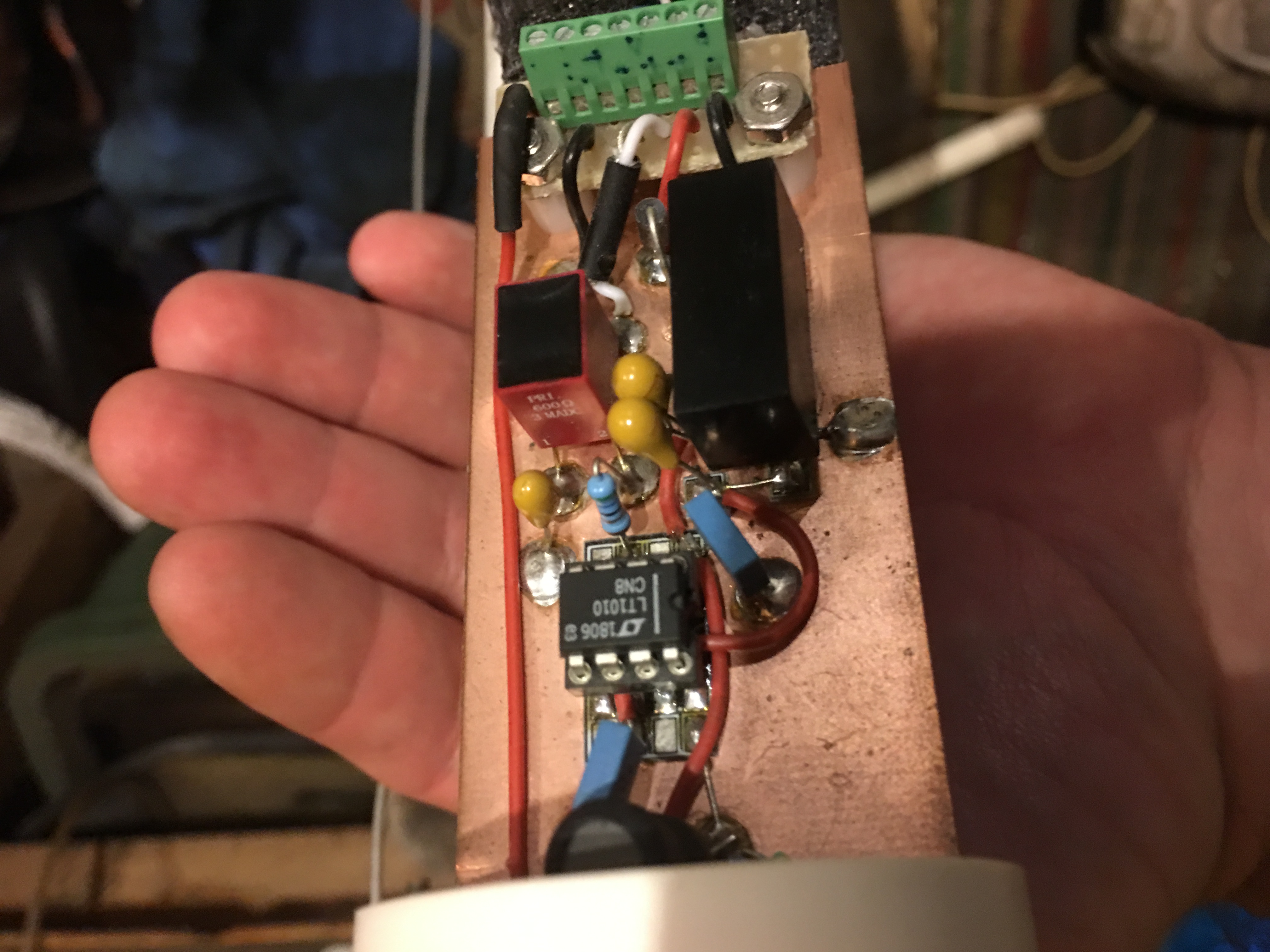
> the squeal of the DC-DC converter. When I pulled out the smaller foam
> core partially, I heard a squeal coming from the DC-DC converter itself.
>
> I had a failure of the DC-DC converter when I first built the VLF
> preamp. It was being powered by the Raspberry Pi box (same power circuit
> as my text box). I had a power failure and when the power was restored,
> the DC-DC converter failed. In both situations, it was being supplied
> with 30VDC, with the limit is 36V. The reason for using 30V is to
> overcome the voltage drop from long cable lengths.
>
> After both failures, there was a low impedance across the input of the
> DC-DC converter causing the supply to be pulled down. Because the input
> and output are isolated, I figured the fault had to have been caused by
> a voltage spike on the input due to power being turned on and off. The
> datasheet mentions that it can withstand 50V spikes at 100ms, but I
> can’t think of anything else that could cause the DC-DC to fail,
> especially that 30V is used to power it and any voltage spike would ride
> on top of that 30V. I contacted XP Power about the issue.
>
> Here is the schematic of the power path. The blocks are the IP2415S
> DC-DC converter.
> I’m powering the DC-DC converter with 30V from another DC-DC converter
> in the test box and Raspberry Pi box (Raspberry Pi box not shown, but
> same circuit). Keep in mind, the length is still relatively short in my
> testing, so cable inductance isn’t the primary reason for the spike.
> Plus, at long lengths, the voltage would be much lower due to voltage
> drop across the length, and I think this was why Paul might not have
> seen this issue when he originally tried and built this design.
>
> To mitigate this problem with the supply voltage at 30V, I decided to
> use a TVS diode across the input of the DC-DC converter. Here is the
> schematic: (my apologies for the TVS diode being backwards)
>
>> Thank you, Tom.
>>
>> The recording will be available later today at
>> hamsci.org/telecons <http://hamsci.org/telecons>.
>>
>> 73 de Nathaniel W2NAF
>>
>> *From:* TangerineSDR <tangerines...@lists.tapr.org
>> <mailto:tangerines...@lists.tapr.org>> *On Behalf Of *Tom
>> McDermott via TangerineSDR
>> *Sent:* Monday, July 26, 2021 10:02 PM
>> *To:* TAPR TangerineSDR Modular Software Defined Radio
>> <tanger...@lists.tapr.org <mailto:tanger...@lists.tapr.org>>
>> *Cc:* Tom McDermott <tom....@gmail.com <mailto:tom....@gmail.com>>
>> *Subject:* [TangerineSDR] Notes from PSWS / TangerineSDR call of
>>
>> Notes from PSWS / TangerineSDR call of 07-26-2021
>>
>> 1. Bill is using chart.js for magnetometer charting. He is setting up
>> a database using Django web and database framework for Python.
>>
>> 2. Scotty is looking at the Intel (Altera) Arria 10 GX FPGA 10GX270
>> for the version 2 Data Engine (supporting 10GE). These FPGAs appear to
>> be more available than the MAX10 FPGAs. The intention is to develop DE
>> Ver 1 and DE Ver 2 in parallel while awaiting FPGA component
>> availability. The 10 GX development boards are pretty expensive.
>>
>> -- Tom, N5EG
>>
>> --
>> Please follow the HamSCI Community Participation Guidelines at
>> http://hamsci.org/hamsci-community-participation-guidelines
>> You received this message because you are subscribed to the Google
>> Groups "HamSCI" group.
>> To unsubscribe from this group and stop receiving emails from it, send
>> an email to hamsci+un...@googlegroups.com
>> https://groups.google.com/d/msgid/hamsci/SA0PR03MB5547CBF733EFEB4D829E659FF2E99%40SA0PR03MB5547.namprd03.prod.outlook.com
> --
> Please follow the HamSCI Community Participation Guidelines at
> http://hamsci.org/hamsci-community-participation-guidelines
> You received this message because you are subscribed to the Google
> Groups "HamSCI" group.
> To unsubscribe from this group and stop receiving emails from it, send
> an email to hamsci+un...@googlegroups.com
> <https://groups.google.com/d/msgid/hamsci/E010F57A-1232-47F1-BFC9-BDC41F1587E9%40gmail.com?utm_medium=email&utm_source=footer>.

Tom McDermott
Please follow the HamSCI Community Participation Guidelines at http://hamsci.org/hamsci-community-participation-guidelines.
---
You received this message because you are subscribed to the Google Groups "HamSCI" group.
To unsubscribe from this group and stop receiving emails from it, send an email to hamsci+un...@googlegroups.com.
To view this discussion on the web visit https://groups.google.com/d/msgid/hamsci/778babd8-9595-528e-997f-b70322aa5c1f%40febo.com.

Julius Madey
73,
Jules-K2KGJ
To view this discussion on the web visit https://groups.google.com/d/msgid/hamsci/CACO3nRSrLuf8ZC0cE3DWyohrV0UissOnSW_i%3D7hi4q63%2BU3E9A%40mail.gmail.com.
Jonathan
John,
Thanks for the suggestion! I think I’ll start with the overvoltage age spike of 50V for 100ms or less based on the datasheet spec of the DC-DC converter. I was thinking of some sort of fusable circuit protection now that I’ll be using a TVS diode to mitigate stress from the follow current.
Tom,
The datasheet wasn’t clear on the need for input filtering. On the output of both the IP2415S, I have 0.1uF ceramic capacitors. In the datasheet, it only mentions a spec of “Input Reflected Rated Current” with a series inductor and shunt capacitor. I don’t really understand exactly what this is, but it lists “20mAp-p through a 12uH inductor and 47uF capacitor”. Nothing else is mentioned about input protection or filtering.
In both situations that the DC-DC failed, the cable length was only 4’ of cat 5. This circuit that was proved and tested by Paul, including the receiver and schematic I attached, did not have such an issue, but the only difference is that the voltage was lower than 30V. That’s why I was thinking it was a turn-on/off spike. I think that in a lot of typical applications, the input voltage isn’t that high, so spikes don’t normally present a problem. The DC-DC that feeds the receiver DC-DC has never failed and it was always fed with 18V or less.
Jules,
You recommend the Schottky diode in parallel with the TVS, then a series PTC, so during a spike, the TVS will conduct and the PTC would fuse, and during a reverse polarity condition, the Schottky diode will conduct with limited current due to the PTC fusing? I can see the benefit that the series PTC in normal a normal circuit condition would drop much less voltage that the Schottky diode.
All in all, I agree with adding some capacitance to filter voltage spikes and reduce or eliminate them. I’ll need to be sure not to exceed the DC-DC max load capacitance, which is 47uF in this case.
But, to me, the most plausible cause for the failures are turn on/off voltage spikes, even with a short length of cable. Adding electrolytics is a bit difficult due to the tight space constraint as seen in my previous email, so I’ll try out the TVS and a PTC. Other than voltage spikes, does anything else come to mind?
Thanks guys.
Jonathan
KC3EEY
Tom McDermott

Phil Erickson
To view this discussion on the web visit https://groups.google.com/d/msgid/hamsci/CACO3nRRfrsP3YdqOPRGpvgtF%3DQoXxBddrud3a%2BTg3Cf68%2B0pLA%40mail.gmail.com.
Jonathan
Hi Jonathan - a concern is that the DC-DC converter input stage would become unstable and oscillatewith the cable inductance. If that happens then there could be high frequency AC voltages present at theinput of the converter. Would those over-voltage the input? Possibly. Would it radiate RFI from the cable? Likely.Good design dictates sufficiently low source impedance to the DC-DC converter. Almost all linear regulatorsrequire it. An electrolytic and ceramic bypass pair right at the DC-DC input would be considered good design by many.-- Tom, N5EG
On Wed, Jul 28, 2021 at 7:30 AM Jonathan <emum...@gmail.com> wrote:
John,
Thanks for the suggestion! I think I’ll start with the overvoltage age spike of 50V for 100ms or less based on the datasheet spec of the DC-DC converter. I was thinking of some sort of fusable circuit protection now that I’ll be using a TVS diode to mitigate stress from the follow current.
Tom,
The datasheet wasn’t clear on the need for input filtering. On the output of both the IP2415S, I have 0.1uF ceramic capacitors. In the datasheet, it only mentions a spec of “Input Reflected Rated Current” with a series inductor and shunt capacitor. I don’t really understand exactly what this is, but it lists “20mAp-p through a 12uH inductor and 47uF capacitor”. Nothing else is mentioned about input protection or filtering.
In both situations that the DC-DC failed, the cable length was only 4’ of cat 5. This circuit that was proved and tested by Paul, including the receiver and schematic I attached, did not have such an issue, but the only difference is that the voltage was lower than 30V. That’s why I was thinking it was a turn-on/off spike. I think that in a lot of typical applications, the input voltage isn’t that high, so spikes don’t normally present a problem. The DC-DC that feeds the receiver DC-DC has never failed and it was always fed with 18V or less.
Jules,
You recommend the Schottky diode in parallel with the TVS, then a series PTC, so during a spike, the TVS will conduct and the PTC would fuse, and during a reverse polarity condition, the Schottky diode will conduct with limited current due to the PTC fusing? I can see the benefit that the series PTC in normal a normal circuit condition would drop much less voltage that the Schottky diode.
All in all, I agree with adding some capacitance to filter voltage spikes and reduce or eliminate them. I’ll need to be sure not to exceed the DC-DC max load capacitance, which is 47uF in this case.
But, to me, the most plausible cause for the failures are turn on/off voltage spikes, even with a short length of cable. Adding electrolytics is a bit difficult due to the tight space constraint as seen in my previous email, so I’ll try out the TVS and a PTC. Other than voltage spikes, does anything else come to mind?
Thanks guys.
Jonathan
KC3EEY
On Tue, Jul 27, 2021 at 9:34 AM Jonathan <emum...@gmail.com> wrote:
Hi Everyone,Before the meeting ended last night, I wanted to discuss the issues I’ve experienced with my VLF active antenna. As I mentioned, the DC-DC converter (XP Power IP2415S) failed after I applied power. I turned the volume up because I wasn’t hearing sferics, and shortly after, I heard the squeal of the DC-DC converter. When I pulled out the smaller foam core partially, I heard a squeal coming from the DC-DC converter itself.

David G. McGaw
David N1HAC
To view this discussion on the web visit https://groups.google.com/d/msgid/hamsci/59FAEE9C-11F5-4CDF-B960-2E583E42E89C%40gmail.com.

Ward Silver
To view this discussion on the web visit https://groups.google.com/d/msgid/hamsci/59FAEE9C-11F5-4CDF-B960-2E583E42E89C%40gmail.com.
Julius Madey
73,
Jules-K2KGJ
To view this discussion on the web visit https://groups.google.com/d/msgid/hamsci/CAFr7d%3DqbQQj4-iEcb_wFnPzbeG6XYO1Q6RV4RhTpX0ihyFxvEQ%40mail.gmail.com.
Ward Silver

HL Serra
To view this discussion on the web visit https://groups.google.com/d/msgid/hamsci/CAFr7d%3DrPHez0M4YR68wUkCCTx7nEWhy5%2BFMZrUnMEgcp4xVXXQ%40mail.gmail.com.
Julius Madey
Chokes can be placed randomly along a longer cable run to avoid common resonance lengths.
73,
Jules-K2KGJ
To view this discussion on the web visit https://groups.google.com/d/msgid/hamsci/CAM4%3DgM92S_eb5OF6ynuDcGZTrcUnyc4zVfLU-HXbGTjxYXYRgA%40mail.gmail.com.
Jonathan
Phil,
Thanks for letting me know. I’ll reach out to Earle for more information.
Ward,
Thank you for that reminder and the great design tip. The feedline I will be using is shielded CAT6. One pair carries DC power and the other carries VLF audio. I plan on grounding the shield too.
Jules,
Would mix 31 be appropriate for VLF? It looks like it’s recommended for a frequency range of 1-300MHz, so it that case, it should eliminate any of those high frequency transients from EFT? They can’t be installed in the conduit, but can be installed on the feedline coming into the Raspberry Pi box.
Thanks.
Jonathan
KC3EEY

George Byrkit
NPS-EC-07-002
NPS-EC-10-001
Jim Breakhall was on the distribution list for these. I suspect Ward Silver has the links, too. They were in an article recently, but I regret not having saved the URLs.
73,
George Byrkit, K9TRV
-----Original Message-----
From: ham...@googlegroups.com <ham...@googlegroups.com> On Behalf Of Jonathan
Sent: Thursday, July 29, 2021 1:24 PM
To: Ward Silver <hwar...@gmail.com>
Cc: Julius Madey <hil...@fairpoint.net>; hamsci <ham...@googlegroups.com>; Tom McDermott <tom....@gmail.com>; TAPR TangerineSDR Modular Software Defined Radio <tanger...@lists.tapr.org>
Subject: Re: [HamSCI] RE: [TangerineSDR] Notes from PSWS / TangerineSDR call of 07-26-2021
Phil,
Thanks for letting me know. I’ll reach out to Earle for more information.
Ward,
Thank you for that reminder and the great design tip. The feedline I will be using is shielded CAT6. One pair carries DC power and the other carries VLF audio. I plan on grounding the shield too.
Jules,
Would mix 31 be appropriate for VLF? It looks like it’s recommended for a frequency range of 1-300MHz, so it that case, it should eliminate any of those high frequency transients from EFT? They can’t be installed in the conduit, but can be installed on the feedline coming into the Raspberry Pi box.
Thanks.
Jonathan
KC3EEY
Blocking common-mode RF current using ferrite chokes is a good technique. So is using shielded cable for everything and metal enclosures bonded together. Jim has several tutorials about this available on his web page (k9yc.com/publish.htm <http://k9yc.com/publish.htm> ) - see the slide show about reducing received noise. This was an evolution of a presentation on common-mode chokes (http://www.yccc.org/Articles/W1HIS/CommonModeChokesW1HIS2006Apr06.pdf) by Chuck Counselman, W1HIS in the context of reduced received noise. (The presentation was created before Type 31 ferrite became available which is a much better material for EMI suppression.)
73, Ward N0AX
<https://www.avast.com/sig-email?utm_medium=email&utm_source=link&utm_campaign=sig-email&utm_content=webmail&utm_term=icon> Virus-free. www.avast.com <https://www.avast.com/sig-email?utm_medium=email&utm_source=link&utm_campaign=sig-email&utm_content=webmail&utm_term=link>
On Wed, Jul 28, 2021 at 3:32 PM Julius Madey <hil...@fairpoint.net <mailto:hil...@fairpoint.net> > wrote:
On that note, I wonder if it would be a good idea to put a common mode choke (multiple turns of the power feed line through an appropriate ferrite mix) in the line ? K9YC's audio RFI paper is a good reference.
73,
Jules-K2KGJ
On 7/28/2021 4:02 PM, Ward Silver wrote:
A quick note - rectifiers, LEDs, or any non-linear devices connected to unshielded cables of any significant length will happily act as mixers or harmonic generators. Whenever one of these is used, put a 0.01uF disc ceramic across it to bypass it at RF.
73, Ward N0AX
On Wed, Jul 28, 2021 at 11:41 AM Jonathan <emum...@gmail.com <mailto:emum...@gmail.com> > wrote:
Hi Tom,
That makes a lot of sense. I’ll try fit a 0.1uF and a 22-47uF electrolytic on the feedline loop.
Thanks again!
Jonathan
KC3EEY
Hi Jonathan - a concern is that the DC-DC converter input stage would become unstable and oscillate
with the cable inductance. If that happens then there could be high frequency AC voltages present at the
input of the converter. Would those over-voltage the input? Possibly. Would it radiate RFI from the cable? Likely.
Good design dictates sufficiently low source impedance to the DC-DC converter. Almost all linear regulators
require it. An electrolytic and ceramic bypass pair right at the DC-DC input would be considered good design by many.
-- Tom, N5EG
On Wed, Jul 28, 2021 at 7:30 AM Jonathan <emum...@gmail.com <mailto:emum...@gmail.com> > wrote:
John,
Thanks for the suggestion! I think I’ll start with the overvoltage age spike of 50V for 100ms or less based on the datasheet spec of the DC-DC converter. I was thinking of some sort of fusable circuit protection now that I’ll be using a TVS diode to mitigate stress from the follow current.
Tom,
The datasheet wasn’t clear on the need for input filtering. On the output of both the IP2415S, I have 0.1uF ceramic capacitors. In the datasheet, it only mentions a spec of “Input Reflected Rated Current” with a series inductor and shunt capacitor. I don’t really understand exactly what this is, but it lists “20mAp-p through a 12uH inductor and 47uF capacitor”. Nothing else is mentioned about input protection or filtering.
In both situations that the DC-DC failed, the cable length was only 4’ of cat 5. This circuit that was proved and tested by Paul, including the receiver and schematic I attached, did not have such an issue, but the only difference is that the voltage was lower than 30V. That’s why I was thinking it was a turn-on/off spike. I think that in a lot of typical applications, the input voltage isn’t that high, so spikes don’t normally present a problem. The DC-DC that feeds the receiver DC-DC has never failed and it was always fed with 18V or less.
Jules,
You recommend the Schottky diode in parallel with the TVS, then a series PTC, so during a spike, the TVS will conduct and the PTC would fuse, and during a reverse polarity condition, the Schottky diode will conduct with limited current due to the PTC fusing? I can see the benefit that the series PTC in normal a normal circuit condition would drop much less voltage that the Schottky diode.
All in all, I agree with adding some capacitance to filter voltage spikes and reduce or eliminate them. I’ll need to be sure not to exceed the DC-DC max load capacitance, which is 47uF in this case.
But, to me, the most plausible cause for the failures are turn on/off voltage spikes, even with a short length of cable. Adding electrolytics is a bit difficult due to the tight space constraint as seen in my previous email, so I’ll try out the TVS and a PTC. Other than voltage spikes, does anything else come to mind?
Thanks guys.
Jonathan
KC3EEY
Hi Everyone,
Before the meeting ended last night, I wanted to discuss the issues I’ve experienced with my VLF active antenna. As I mentioned, the DC-DC converter (XP Power IP2415S) failed after I applied power. I turned the volume up because I wasn’t hearing sferics, and shortly after, I heard the squeal of the DC-DC converter. When I pulled out the smaller foam core partially, I heard a squeal coming from the DC-DC converter itself.
<image3.jpeg>
I had a failure of the DC-DC converter when I first built the VLF preamp. It was being powered by the Raspberry Pi box (same power circuit as my text box). I had a power failure and when the power was restored, the DC-DC converter failed. In both situations, it was being supplied with 30VDC, with the limit is 36V. The reason for using 30V is to overcome the voltage drop from long cable lengths.
After both failures, there was a low impedance across the input of the DC-DC converter causing the supply to be pulled down. Because the input and output are isolated, I figured the fault had to have been caused by a voltage spike on the input due to power being turned on and off. The datasheet mentions that it can withstand 50V spikes at 100ms, but I can’t think of anything else that could cause the DC-DC to fail, especially that 30V is used to power it and any voltage spike would ride on top of that 30V. I contacted XP Power about the issue.
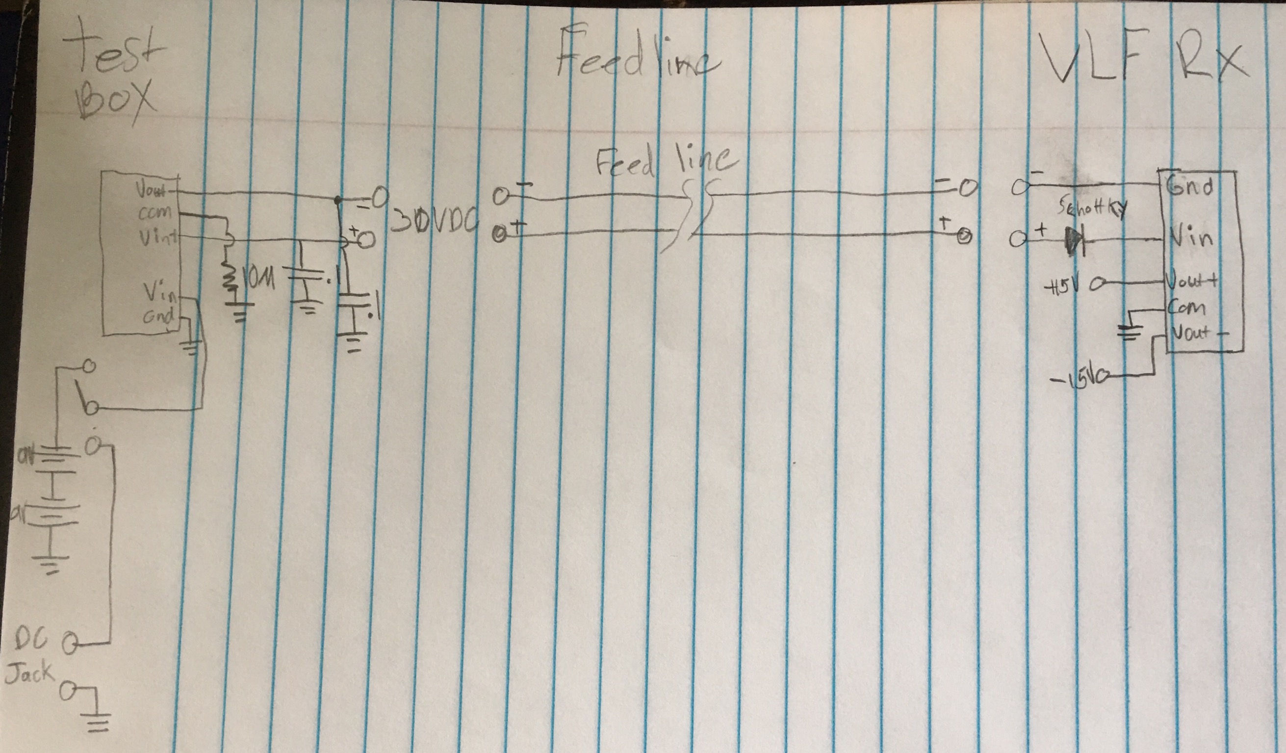
Here is the schematic of the power path. The blocks are the IP2415S DC-DC converter.
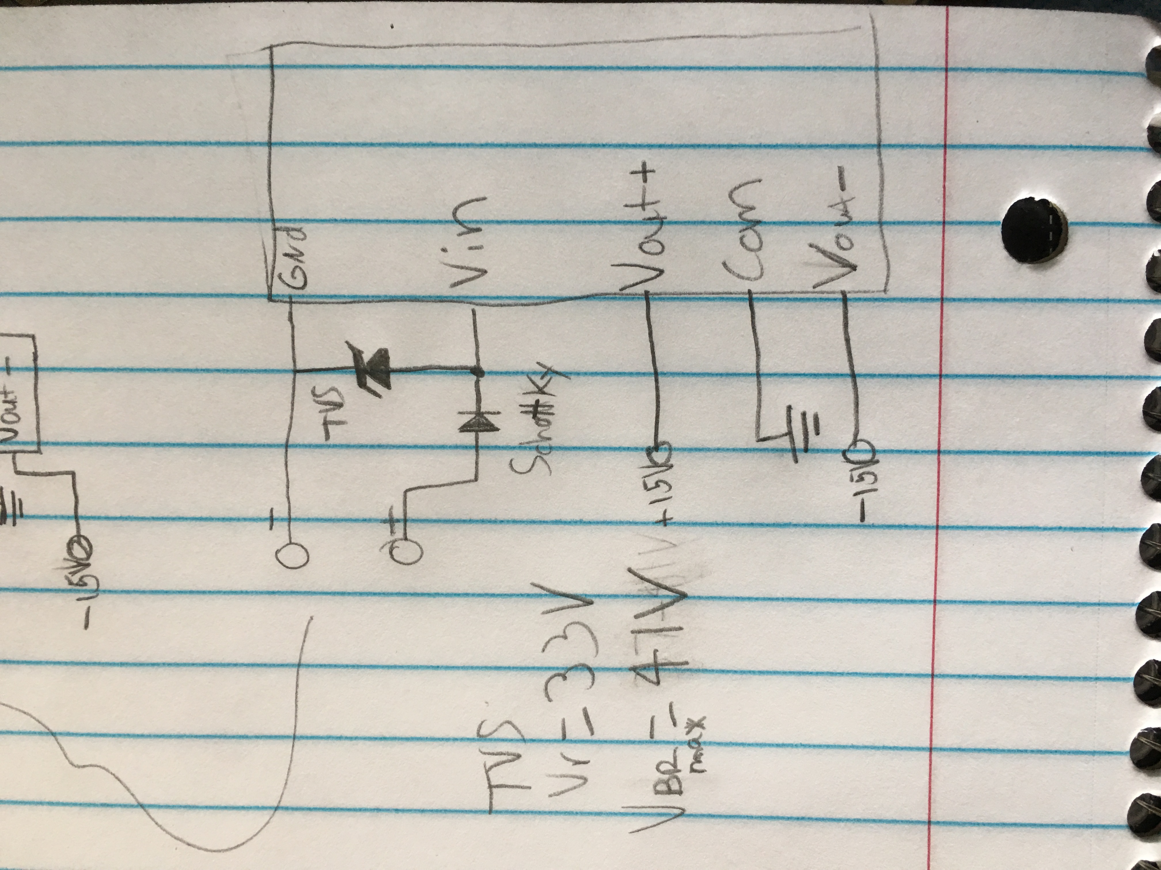
To mitigate this problem with the supply voltage at 30V, I decided to use a TVS diode across the input of the DC-DC converter. Here is the schematic: (my apologies for the TVS diode being backwards)
So the questions I have are: do you also think it could be voltage spikes that caused the failures, and if so, was my choice of TVS diode adequate. Also, one important question, if I connect the anode of the TVS diode to the receiver side ground, will I lose isolation? I know that during spike current conduction, I will. I’m sure I can still get adequate protection with the TVS diode anode connected to the negative of the isolated power loop too, but I just wanted to be sure.
Lastly, since the magnetometer board will undergo another revision, I feel it may be worth it to add some sort or adjustable regulator or use of an external power source (not connected to the 5V pin of the Pi header) because even with paralleling wires or pairs, some installations will require very long lengths (especially since interference-free locations are often far away from the shack) and the voltage may drop to where the LDO cant regulate. Using a higher voltage at the Pi end (like I do with the VLF preamp) may be required for some installations. I think this should be considered if it already wasn’t addressed.
Jonathan
KC3EEY
On Jul 27, 2021, at 7:21 AM, Dr. Nathaniel A. Frissell Ph.D. <nathaniel...@scranton.edu <mailto:nathaniel...@scranton.edu> > wrote:
Thank you, Tom.
The recording will be available later today at
From: TangerineSDR <tangerines...@lists.tapr.org <mailto:tangerines...@lists.tapr.org> >
On Behalf Of Tom McDermott via TangerineSDR
Sent: Monday, July 26, 2021 10:02 PM
Cc: Tom McDermott <tom....@gmail.com <mailto:tom....@gmail.com> >
Subject: [TangerineSDR] Notes from PSWS / TangerineSDR call of 07-26-2021
Notes from PSWS / TangerineSDR call of 07-26-2021
1. Bill is using chart.js for magnetometer charting. He is setting up a database using Django web and database framework for Python.
2. Scotty is looking at the Intel (Altera) Arria 10 GX FPGA 10GX270 for the version 2 Data Engine (supporting 10GE). These FPGAs appear to be more available than the MAX10 FPGAs. The intention is to develop DE Ver 1 and DE Ver 2 in parallel
while awaiting FPGA component availability. The 10 GX development boards are pretty expensive.
-- Tom, N5EG
--
Please follow the HamSCI Community Participation Guidelines at http://hamsci.org/hamsci-community-participation-guidelines.
---
You received this message because you are subscribed to the Google Groups "HamSCI" group.
To view this discussion on the web visit https://groups.google.com/d/msgid/hamsci/SA0PR03MB5547CBF733EFEB4D829E659FF2E99%40SA0PR03MB5547.namprd03.prod.outlook.com <https://groups.google.com/d/msgid/hamsci/SA0PR03MB5547CBF733EFEB4D829E659FF2E99%40SA0PR03MB5547.namprd03.prod.outlook.com?utm_medium=email&utm_source=footer> .
--
Please follow the HamSCI Community Participation Guidelines at http://hamsci.org/hamsci-community-participation-guidelines.
---
You received this message because you are subscribed to the Google Groups "HamSCI" group.
To view this discussion on the web visit https://groups.google.com/d/msgid/hamsci/59FAEE9C-11F5-4CDF-B960-2E583E42E89C%40gmail.com <https://groups.google.com/d/msgid/hamsci/59FAEE9C-11F5-4CDF-B960-2E583E42E89C%40gmail.com?utm_medium=email&utm_source=footer> .
<https://www.avast.com/sig-email?utm_medium=email&utm_source=link&utm_campaign=sig-email&utm_content=webmail&utm_term=icon> Virus-free. www.avast.com <https://www.avast.com/sig-email?utm_medium=email&utm_source=link&utm_campaign=sig-email&utm_content=webmail&utm_term=link>
Please follow the HamSCI Community Participation Guidelines at http://hamsci.org/hamsci-community-participation-guidelines.
---
You received this message because you are subscribed to the Google Groups "HamSCI" group.
To view this discussion on the web visit https://groups.google.com/d/msgid/hamsci/CAFr7d%3DqbQQj4-iEcb_wFnPzbeG6XYO1Q6RV4RhTpX0ihyFxvEQ%40mail.gmail.com <https://groups.google.com/d/msgid/hamsci/CAFr7d%3DqbQQj4-iEcb_wFnPzbeG6XYO1Q6RV4RhTpX0ihyFxvEQ%40mail.gmail.com?utm_medium=email&utm_source=footer> .
--
Please follow the HamSCI Community Participation Guidelines at http://hamsci.org/hamsci-community-participation-guidelines.
---
You received this message because you are subscribed to the Google Groups "HamSCI" group.
To view this discussion on the web visit https://groups.google.com/d/msgid/hamsci/29865318-FCCB-4A1E-B3DB-EFF738A19F04%40gmail.com <https://groups.google.com/d/msgid/hamsci/29865318-FCCB-4A1E-B3DB-EFF738A19F04%40gmail.com?utm_medium=email&utm_source=footer> .
Julius Madey
73,
Jules-K2KGJ
Jonathan
<image1.jpeg>
I’m powering the DC-DC converter with 30V from another DC-DC converter in the test box and Raspberry Pi box (Raspberry Pi box not shown, but same circuit). Keep in mind, the length is still relatively short in my testing, so cable inductance isn’t the primary reason for the spike. Plus, at long lengths, the voltage would be much lower due to voltage drop across the length, and I think this was why Paul might not have seen this issue when he originally tried and built this design.
To mitigate this problem with the supply voltage at 30V, I decided to use a TVS diode across the input of the DC-DC converter. Here is the schematic: (my apologies for the TVS diode being backwards)

Dana Whitlow
To view this discussion on the web visit https://groups.google.com/d/msgid/hamsci/CEED81D7-C092-4FC5-A974-58F00762DB6D%40gmail.com.

Bob McGwier
To view this discussion on the web visit https://groups.google.com/d/msgid/hamsci/CEED81D7-C092-4FC5-A974-58F00762DB6D%40gmail.com.