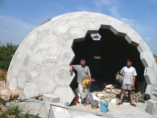
Concrete Geodesic Dome

TaffGoch

Gravity
--
--
You received this message because you are subscribed to the "Geodesic Help" Google Group
--
To unsubscribe from this group, send email to GeodesicHelp...@googlegroups.com
--
To post to this group, send email to geodes...@googlegroups.com
--
For more options, visit http://groups.google.com/group/geodesichelp?hl=en
---
You received this message because you are subscribed to the Google Groups "Geodesic Help Group" group.
To unsubscribe from this group and stop receiving emails from it, send an email to geodesichelp...@googlegroups.com.
To view this discussion on the web visit https://groups.google.com/d/msgid/geodesichelp/CAP3j8HwuemRuD61%2BwcNVVAcHmEKFykJ9vs6fsLcoatHQEoHQoQ%40mail.gmail.com.

Dick Fischbeck
--

valle....@gmail.com

RC

Pedro valle
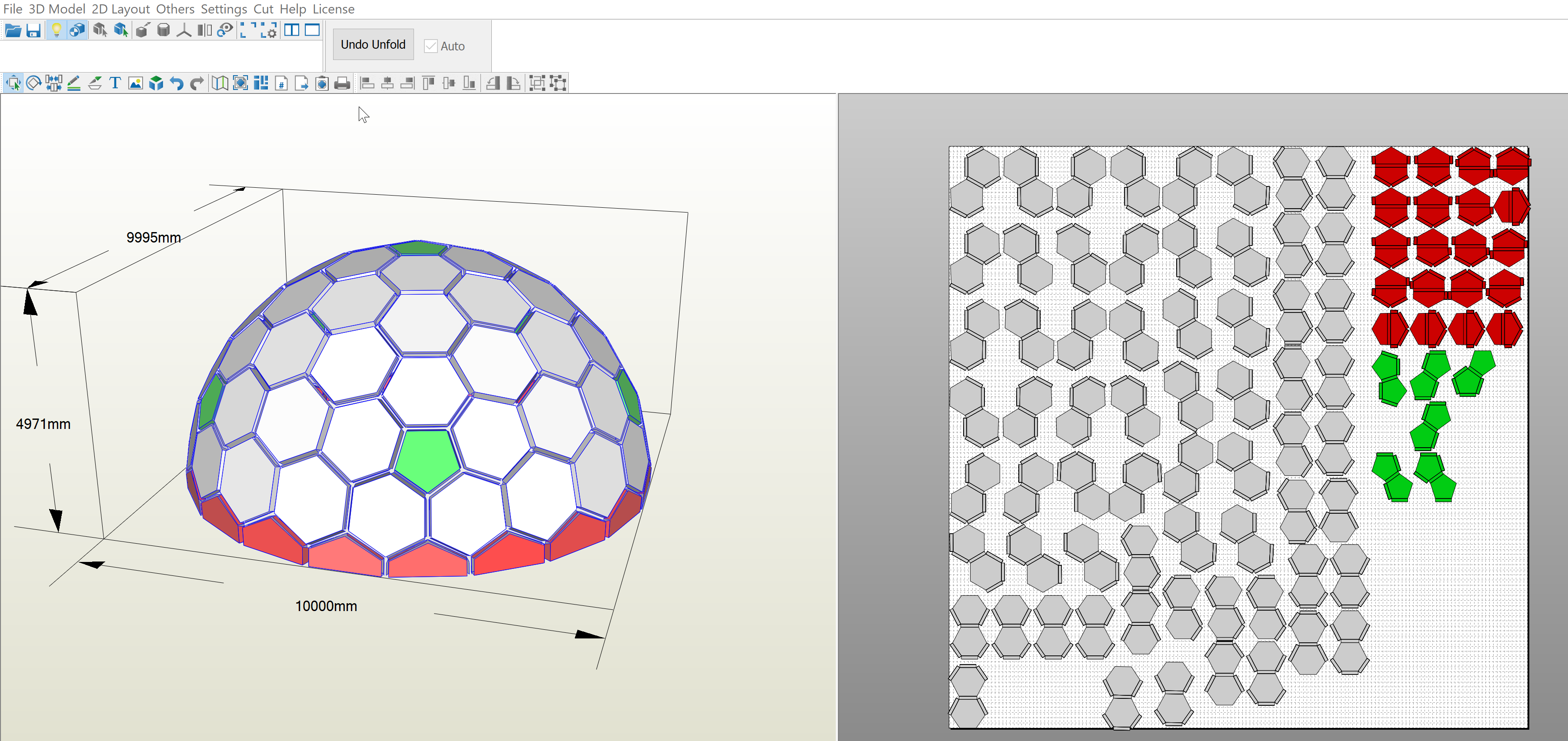
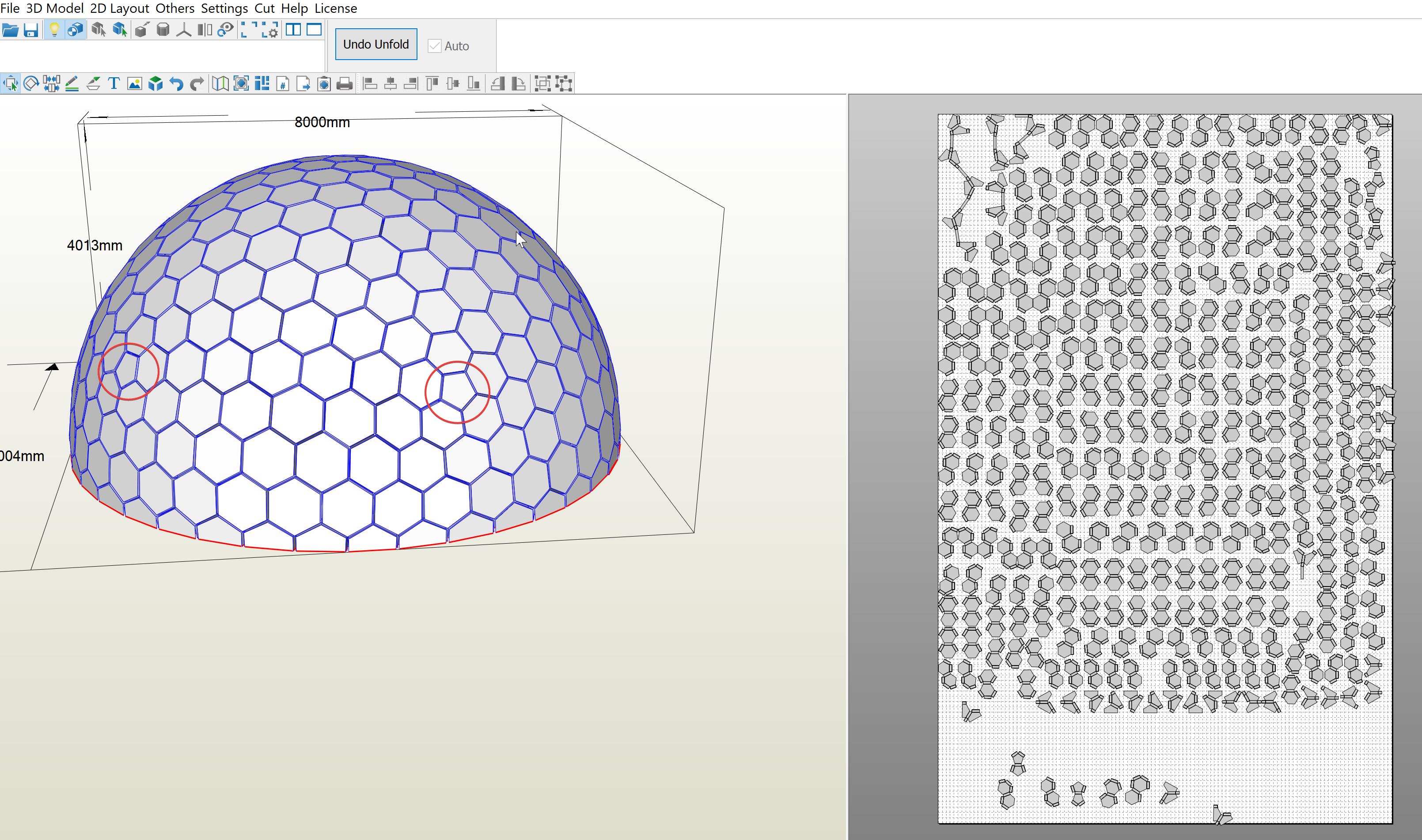
manage to build an ok dome. in Blender. made the dome, then export to OBJ and open in Pepakura and unfold the dome, but I can't make the hexagons small like the pic above, so my molds are maybe doble the size, the dome is 10 mts on diameter. I'm planning to build this dome with aircrate in summer Ill post my progress on June. thanks to these group for all the help.
RC

Ashok Mathur
Ashok
--
--
You received this message because you are subscribed to the "Geodesic Help" Google Group
--
To unsubscribe from this group, send email to GeodesicHelp...@googlegroups.com
--
To post to this group, send email to geodes...@googlegroups.com
--
For more options, visit http://groups.google.com/group/geodesichelp?hl=en
---
You received this message because you are subscribed to the Google Groups "Geodesic Help Group" group.
To unsubscribe from this group and stop receiving emails from it, send an email to geodesichelp...@googlegroups.com.
To view this discussion on the web visit https://groups.google.com/d/msgid/geodesichelp/b8ae8b22-84f6-4aab-81ee-1846dd3d0802n%40googlegroups.com.

lemondealc
To view this discussion on the web visit https://groups.google.com/d/msgid/geodesichelp/CAD-a3OiqRoL0ZZdP-CvO%2BX6wtZ-WxbY5PrSSB2NfPBi_uf-S%2Bg%40mail.gmail.com.
Pedro valle
Pedro valle
Hi Ashok
Ashok Mathur
To view this discussion on the web visit https://groups.google.com/d/msgid/geodesichelp/21086bd6-5ad0-403a-9483-55b66233371fn%40googlegroups.com.
Pedro valle


Dx G
RC
Pedro valle
RC
Pedro valle
Pedro valle

Erich Nolan Bertussi
To view this discussion on the web visit https://groups.google.com/d/msgid/geodesichelp/5E5A45E1-2CFB-4868-9288-30144C59BAE0%40gmail.com.

Patrick McDonnell

Levente Likhanecz

--
--
You received this message because you are subscribed to the "Geodesic Help" Google Group
--
To unsubscribe from this group, send email to GeodesicHelp...@googlegroups.com
--
To post to this group, send email to geodes...@googlegroups.com
--
For more options, visit http://groups.google.com/group/geodesichelp?hl=en
---
You received this message because you are subscribed to the Google Groups "Geodesic Help Group" group.
To unsubscribe from this group and stop receiving emails from it, send an email to geodesichelp...@googlegroups.com.
To view this discussion on the web visit https://groups.google.com/d/msgid/geodesichelp/CAP3j8HwuemRuD61%2BwcNVVAcHmEKFykJ9vs6fsLcoatHQEoHQoQ%40mail.gmail.com.
Dx G
You said
"Obviously trying to keep the number of different molds to a minimum."
An important part of choosing the right design of a dome (or almost anything, for that matter) is keeping the variation in parts and part size to a minimum. This reduces cost, increases simplicity and makes success more likely.
Firstly, with respect to concrete block domes, if you look, you will specifically see that this was partly addressed in Robert's patent.
https://patents.google.com/patent/US10487494B1/en
He discusses using mortar to fill the space between blocks when they are used for a larger or smaller dome, as this changes the dihedral angles. There are other ways to do that, but its a start.
However, there are also some options in design that are very frequently (and sadly) overlooked. Some have been discussed in this forum under various topics. I've been looking at these myself for the creased diamond panel domes I've been evaluating. So let me mention a few here.
1) Pentakis Dodecahedron
This is similar to a 2 frequency Class 2 Method 3 (triacon). The nice part is like the triacon, although all the panels are the same, in the Pent Dod, all the dihedral angles are the same. There are some limits on dome size, but the edge-up configuration provides a nice truncation. Gerry posted some really good material on this.
2) Edge up 3f
A dome that has been popular for decades is the 3f ico alternate. However, one approach few people seem to consider is the edge-up configuration, which provides a flat truncation for a hemisphere. People often bring up the Kruske dome, which has its assets, but low variation in parts is not one of them.
3) Catalan solids
This is an entire class of polyhedrons with this description:
"Catalan solids are a group of thirteen convex polyhedra that are the duals of the Archimedean solids. They are characterized by having faces that are all the same type, constant dihedral angles, and specific symmetry properties, but their vertices are not symmetric."
Excellent resource. There are lots of them if you look.
https://dmccooey.com/polyhedra/
https://dmccooey.com/polyhedra/Catalan.html
https://www.qfbox.info/4d/catalan3d
https://mathworld.wolfram.com/CatalanSolid.html
There is more out there, but this is a good start for you and others that understand the value of reducing variation in the structure.
Remember, every success begins with the decision to try.
John F. Kennedy
Let us know if this helps and what else might.
Dx G
mcdonn...@gmail.com
Thanks Levente,
I had looked at Chris model a few years ago but I could not figure out how to re-create this from first principals and adapt to different frequency.
This definitely would meet my objectives, when panelised the panels are very close to being perfect with only tiny error.
Does anybody know how to go about creating a model like this from first principals?


Very minor “step” at internal faces.

Cheers,
Paddy
From: geodes...@googlegroups.com <geodes...@googlegroups.com> On Behalf Of Levente Likhanecz
Sent: Thursday, 1 January 2026 8:39 PM
To: geodes...@googlegroups.com
Subject: Re: Concrete Geodesic Dome

Chris Kitrick has this hexagonal dome. Its obviously looks higher frequency. All hexa is flat, and all vertices on sphere
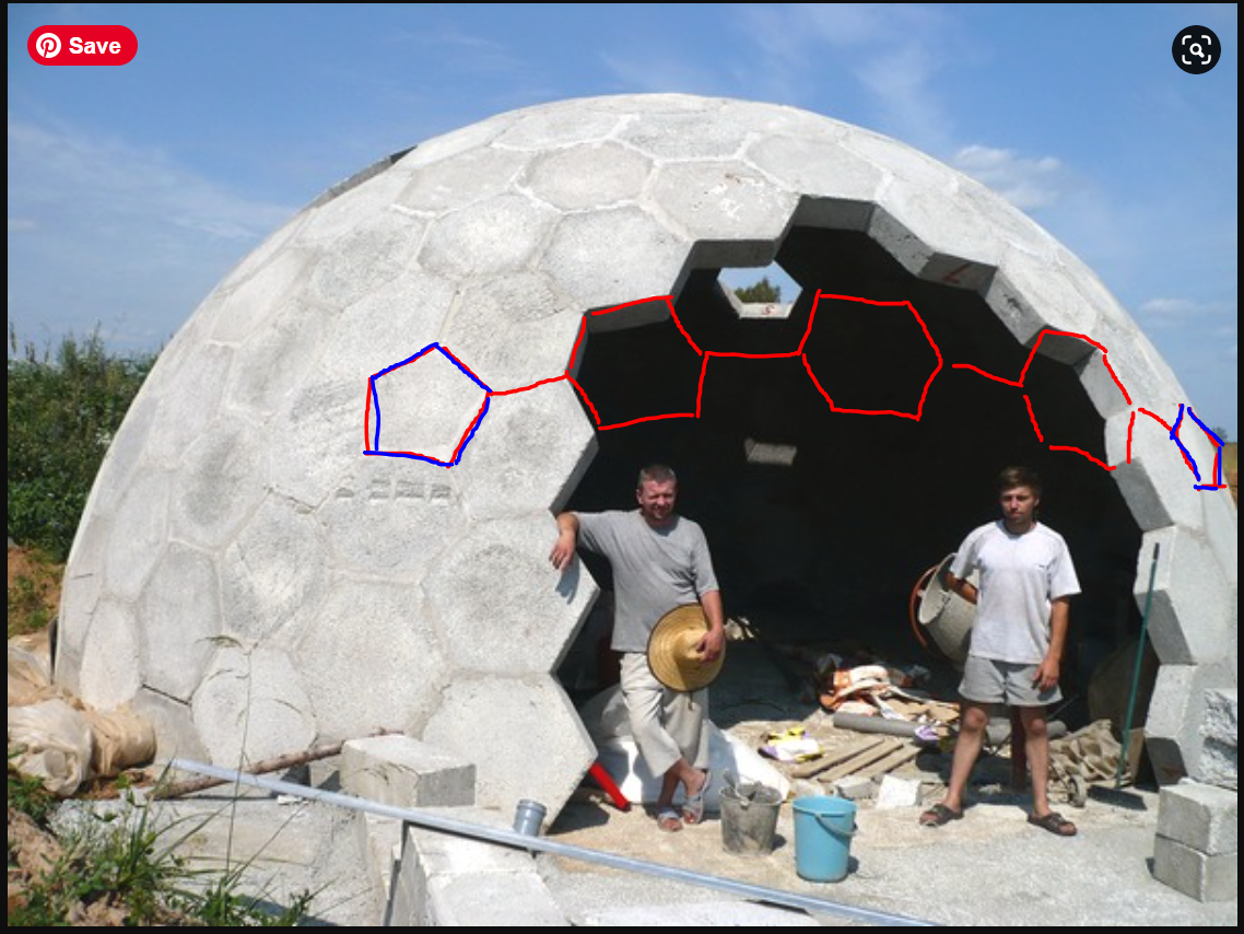
On Wed, Jun 8, 2022 at 12:51 AM TaffGoch <taff...@gmail.com> wrote:
Hi, all,
Has anyone seen any information on this dome?

To view this discussion visit https://groups.google.com/d/msgid/geodesichelp/CAOkvED%3DoUWMQ70a8TEWSExGvHDYN1HapHSSz-d4EYfjD6BHadg%40mail.gmail.com.
mcdonn...@gmail.com
Thanks for the response Dx G,
I am aware of Roberts work and patent but this is not really what I am after.
The other geometry you mention is interesting but I could not find any higher frequency (smallest panel size) divisions of this type of geometry?
What Chris Kitrick modelled in sketchup looks perfect but I would like to understand how to replicate this from first principals.
Cheers,
Paddy
From: geodes...@googlegroups.com <geodes...@googlegroups.com> On Behalf Of Dx G
Sent: Friday, 2 January 2026 1:50 AM
To: Geodesic Help Group <geodes...@googlegroups.com>
Subject: Re: Concrete Geodesic Dome
Patick,
Chris Kitrick has this hexagonal dome. Its obviously looks higher frequency. All hexa is flat, and all vertices on sphere
On Wed, Jun 8, 2022 at 12:51 AM TaffGoch <taff...@gmail.com> wrote:
Hi, all,
Has anyone seen any information on this dome?

To view this discussion visit https://groups.google.com/d/msgid/geodesichelp/134974a5-0470-4888-a864-e8d6c8c025f3n%40googlegroups.com.
Dx G
Levente Likhanecz
To view this discussion visit https://groups.google.com/d/msgid/geodesichelp/000001dc7b98%247717b4c0%2465471e40%24%40gmail.com.
Levente Likhanecz
To view this discussion visit https://groups.google.com/d/msgid/geodesichelp/001601dc7b9a%24d9d6b820%248d842860%24%40gmail.com.
TaffGoch
%20bricks.jpg?part=0.1&view=1)
mcdonn...@gmail.com
Hi Levente,
I am not sure I follow your responses, I am trying to understand how to construct this type of geometry from first principals.
Looking back through the posts, from the example SketchUp file that you provided it unless I am mistaken looks like Chris provided guidance on the geometry:
Right
Spherical
Triangle a b c A B C
----------------------------------------------------------------------------------------------------------
t[00] 3.553711440822 2.578525175352 4.389661472179 54.080004313636 35.999999999999 90.000000000000
t[01] 6.834457847956 2.578525175352 7.302536379205 69.425611380982 20.728385258139 90.000000000000
t[02] 6.084041403983 4.046366665742 7.302536379205 56.494384305383 33.720741822183 90.000000000000
t[03] 6.391704213641 3.539091538968 7.302536379205 61.142976945229 29.054694637655 90.000000000000
t[04] 6.723588499164 3.539091538968 7.594356471029 62.362638749389 27.845319767203 90.000000000000
t[05] 6.514490666570 3.911735747030 7.594356471029 59.145366825843 31.077340116398 90.000000000000
t[06] 6.933642498040 4.046366665742 8.022995142563 59.875534090283 30.369702011965 90.000000000000
t[07] 7.010223195830 3.911735747030 8.022995142563 60.979099083874 29.260595976070 90.000000000000
t[08] 7.037872451809 4.046366665742 8.113092799663 60.248931819435 30.000000000000 90.000000000000
Do you know how to calculate this or what the theory is behind this?
To view this discussion visit https://groups.google.com/d/msgid/geodesichelp/CAOkvEDnBpTyUMprekpwMK0wNR29i8%2BShYV7GD5%2BGpYPPtAW6Jg%40mail.gmail.com.
mcdonn...@gmail.com
Thanks Taff,
I am trying to create this type of flat panel geometry myself. I would probably want higher frequency than this.
I am fine modelling regular domes from first principals but it seems like there must be a special trick required to get geometry similar to the Chris Kitrick example provided by Levente.
Cheers,
Paddy
From: geodes...@googlegroups.com <geodes...@googlegroups.com> On Behalf Of TaffGoch
Sent: Friday, 2 January 2026 5:36 PM
To: geodes...@googlegroups.com
Subject: Re: Concrete Geodesic Dome
Patrick,
It is, apparently, an 8-frequency (version-II) subdivision, 8v(4,4)

The unique "brick" count, if I recall, is 10, with one brick mirrored, so 11 molds.
This applies to this particular SketchUp model. Other subdivision methods may produce lower count.
Scaling in SketchUp can be tricky. Don't expect the "push/pull" tool to provide much help with producing brick thickness.
The "scale" tool provides better results, but takes more patience in modeling.
-Taff
(David Price)
--
--
You received this message because you are subscribed to the "Geodesic Help" Google Group
--
To unsubscribe from this group, send email to GeodesicHelp...@googlegroups.com
--
To post to this group, send email to geodes...@googlegroups.com
--
For more options, visit http://groups.google.com/group/geodesichelp?hl=en
---
You received this message because you are subscribed to the Google Groups "Geodesic Help Group" group.
To unsubscribe from this group and stop receiving emails from it, send an email to geodesichelp...@googlegroups.com.
To view this discussion visit https://groups.google.com/d/msgid/geodesichelp/CAP3j8HxvzsuB_yNzJh8kubSVUBMn2jag38wpLKQibLVJAFcnFA%40mail.gmail.com.
Levente Likhanecz
it needs only 5 molds, 1 penta and 4 hexagon, those extracted on the left side
To view this discussion visit https://groups.google.com/d/msgid/geodesichelp/000001dc7be7%247e4eaf60%247aec0e20%24%40gmail.com.

Chris Kitrick
mcdonn...@gmail.com
Thanks Chris,
I did find those references and tried to follow them but alas I could not figure out how following the calculations arrived at the table below.
Do you do these calculations by hand or use excel or a computer program to assist.
Do you have a worked example that you could share?
Your response is much appreciated.
Best regards Paddy
To view this discussion visit https://groups.google.com/d/msgid/geodesichelp/bf397da0-1e87-4326-8a30-381592e2c6c1n%40googlegroups.com.

Bryan L
To view this discussion visit https://groups.google.com/d/msgid/geodesichelp/000c01dc7d0e%2432499710%2496dcc530%24%40gmail.com.
Levente Likhanecz

the blue uni strut, all same
in skp everybody can check / reproduce.
steps to build:
1. the blue is the original icosahedral projection.
3. a connect the 4 vertices. to get the green plane plane


i extend the yellow plane, to have intersection line with magenta plane.
do the "kruschke" vertice projection to have the remaining vertices of yellow:


mcdonn...@gmail.com
Thanks Levente!
I really appreciate the time you took to do this, I followed your simple instructions and was able to replicate this method with success.
Do you think this method would work on a 9V? I will try later when I get time.

Thanks again.
Paddy
From: geodes...@googlegroups.com <geodes...@googlegroups.com> On Behalf Of Levente Likhanecz
Sent: Monday, 5 January 2026 6:10 AM
To: geodes...@googlegroups.com
Subject: Re: Concrete Geodesic Dome
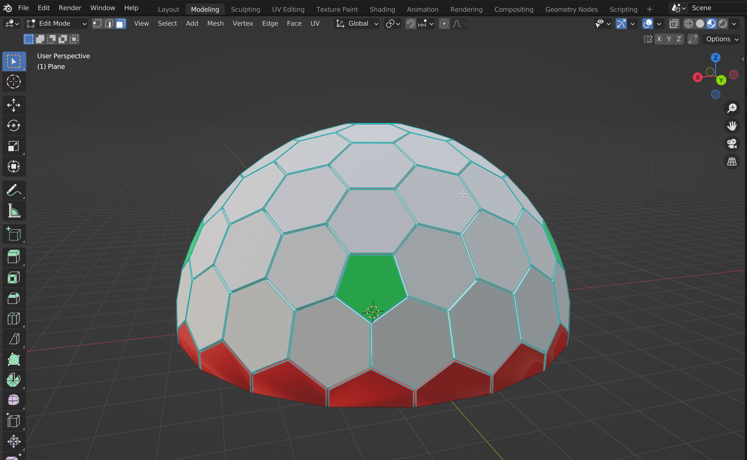
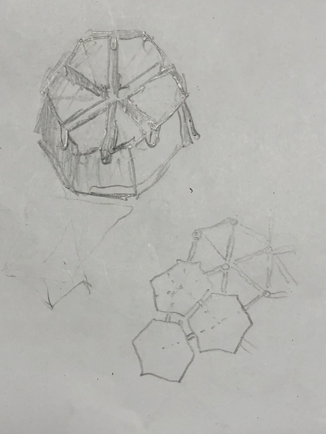
just i pulled a hexapen on 6V icosahedron.
the red-yellow-green-blue all flat (hope so), all vertices pulled to sphere. (with kruschke method)
the blue uni strut, all same
in skp everybody can check / reproduce.
steps to build:
1. the blue is the original icosahedral projection.
2. the blue i rotate 72 degrees around sphere center-icosa triangle tip axle.
3. a connect the 4 vertices. to get the green plane plane

4. the green / magenta plane(= icosa triangle side), intersection, with sphere radius -> intersect the +2 vertices of the gree hexagon:

5. once i have the green hexa, then i have the yellow plane.
i extend the yellow plane, to have intersection line with magenta plane.
do the "kruschke" vertice projection to have the remaining vertices of yellow:

To view this discussion visit https://groups.google.com/d/msgid/geodesichelp/CAOkvEDn7_pX45OO3VKVhyVbK3-5nQH6Cedwzj98oQtyy4Ysvvg%40mail.gmail.com.
mcdonn...@gmail.com
Hi Bryan,
I had tried this method in the past and it did not get the level of standardisation that I was after.
Chris’ method seems like the ultimate solution but alas with the information available figuring out the maths is beyond my abilities.
What Leventhe came up with for 6V looks very promising if the methods can be applied to any frequency.
Cheers,
Paddy
Bryan L
To view this discussion visit https://groups.google.com/d/msgid/geodesichelp/002b01dc7df3%244c6a6bc0%24e53f4340%24%40gmail.com.
Levente Likhanecz
one more thought, let say you have a non flat hexa, you can check which 3 vertices form a plane where the remaining "out of plane" vertices the least out of plane, that way the shifted vertices should stay closer to their original, less distorsion.
To view this discussion visit https://groups.google.com/d/msgid/geodesichelp/002b01dc7df3%244c6a6bc0%24e53f4340%24%40gmail.com.
Bryan L
To view this discussion visit https://groups.google.com/d/msgid/geodesichelp/CAOkvEDm5p5px5vX84cEkQ5rmjT9D7WKjWdZcpJuRG7aTdk0Tpg%40mail.gmail.com.
Levente Likhanecz
To view this discussion visit https://groups.google.com/d/msgid/geodesichelp/CABWq%3Di52D41pg%3DkZWUo-F7EyYt22Dy1fs%3DG0ciJ2Vr8G4tD8Sg%40mail.gmail.com.
Levente Likhanecz
following the previous method, just i had to select planes to intersect little different.
1. phase the blue is the standard projection. then next, the green hex i had to adjust the 2 blue circled vertices to lay on the red handdrawn trapezoid flat (intersect with icosa trianle side flat).

from there the red triangle across the edge of 2 icosa triangle. on the (red triangle --- icosa side) intersect i circle out the 4th vertice of the red plane.
this point will bi the "5." vertice

the bluecircled red triangle plane i extend (rotate a copy) to have intersecting line with the icosa side plane.
on the side plane compass out the sphere radius intersect with the intersection line, and have the last vertice which scribe out the pentagon later.


To view this discussion visit https://groups.google.com/d/msgid/geodesichelp/CABWq%3Di52D41pg%3DkZWUo-F7EyYt22Dy1fs%3DG0ciJ2Vr8G4tD8Sg%40mail.gmail.com.
Levente Likhanecz

mcdonn...@gmail.com
Hi Levente,
Than you again for spending the time to do this and provide the great explanation of your method. This really helped me get past by mental block.
This has finally clicked for me and I am comfortable modelling these. I ended up developing my own method which is slightly different than yours.


Cheers,
Paddy
From: geodes...@googlegroups.com <geodes...@googlegroups.com> On Behalf Of Levente Likhanecz
Sent: Monday, 5 January 2026 10:56 PM
To: geodes...@googlegroups.com
Subject: Re: Concrete Geodesic Dome
i succeded to geometrically design a 9V hexa dome, all flat all vertices unit radius
following the previous method, just i had to select planes to intersect little different.
1. phase the blue is the standard projection. then next, the green hex i had to adjust the 2 blue circled vertices to lay on the red handdrawn trapezoid flat (intersect with icosa trianle side flat).

2. once i had the green (and blue) i rotated 72 degrees to have a neighboring icosa triangle (on the right side of the pic.)
from there the red triangle across the edge of 2 icosa triangle. on the (red triangle --- icosa side) intersect i circle out the 4th vertice of the red plane.
then the 2 red plane i intersect, from their intersection line i draw a new plane from sphere center, on that plane a compass out the sphere radius, to intersect the radius arc with the 2 redplanes intersection line.
this point will bi the "5." vertice

the last vertice i find from the point 5. i mirror to get the orange hexagon (because it is already flat)
the bluecircled red triangle plane i extend (rotate a copy) to have intersecting line with the icosa side plane.
on the side plane compass out the sphere radius intersect with the intersection line, and have the last vertice which scribe out the pentagon later.


To view this discussion visit https://groups.google.com/d/msgid/geodesichelp/CAOkvEDmkXRsiyMNq3dwXbY-j9CM8aDu3Gvp%3Dor5cJBt8DETh-w%40mail.gmail.com.
mcdonn...@gmail.com
Thank Bryan,
I am very interested to see what you come up with using Chris’ method. I would really like to understand it but I read and re-read his papers today and to me (without background in spherical maths) there is just not enough information there for me to figure it out.
Thanks for the wiki links.
To view this discussion visit https://groups.google.com/d/msgid/geodesichelp/CABWq%3Di52D41pg%3DkZWUo-F7EyYt22Dy1fs%3DG0ciJ2Vr8G4tD8Sg%40mail.gmail.com.
Levente Likhanecz

from icosa triangle's centerpoint i split the arc from sphere center 3 part (i draw a 3 segment arc between icosa center and bottom line)
the top segment (pie) lower edge intersect with the icosa triangle face, there will be the modified central hexagon bottom side.
this bottom side line rotate around 60-60-60...
will cut out the red colored new central hexagon.
now i can project out the red hexagon to the sphere radius, getting the blue hexas.
this modified hexa i can put all four pieces.

To view this discussion visit https://groups.google.com/d/msgid/geodesichelp/002f01dc7eee%24ebe01640%24c3a042c0%24%40gmail.com.
mcdonn...@gmail.com
Thanks yet again Levente,
I can follow the method to get the blue hexagons but it looks like the other hexagons are also not standard projections, how did you derive the geometry for these?
Cheers,
Paddy
From: geodes...@googlegroups.com <geodes...@googlegroups.com> On Behalf Of Levente Likhanecz
Sent: Wednesday, 7 January 2026 1:12 AM
To: geodes...@googlegroups.com
Subject: Re: Concrete Geodesic Dome
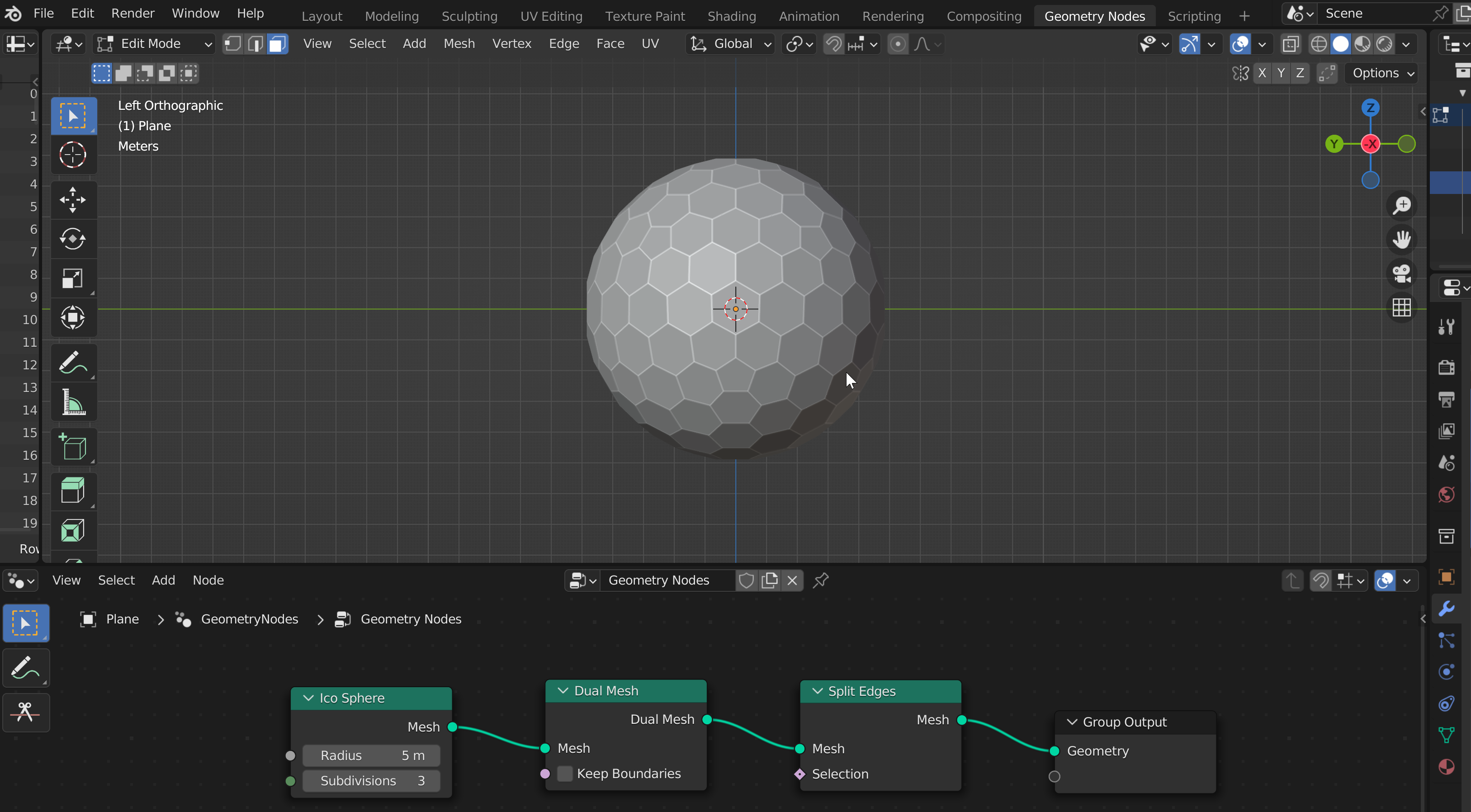
I found geometrically doable 9V 5 mold solution. 
the trick is i dont use the standard central hexagon. instead i split the space for 2 similar (but smaller).
on the icosa triangle i mark the weight point (from tip to opposit side middle point)
from icosa triangle's centerpoint i split the arc from sphere center 3 part (i draw a 3 segment arc between icosa center and bottom line)
the top segment (pie) lower edge intersect with the icosa triangle face, there will be the modified central hexagon bottom side.
this bottom side line rotate around 60-60-60...
will cut out the red colored new central hexagon.
now i can project out the red hexagon to the sphere radius, getting the blue hexas.
this modified hexa i can put all four pieces.

To view this discussion visit https://groups.google.com/d/msgid/geodesichelp/CAOkvEDkxMO%3Dd029jwcF2scXhWiD3hquMrEYHnXVovGeWGfzYZw%40mail.gmail.com.
Bryan L
To view this discussion visit https://groups.google.com/d/msgid/geodesichelp/002f01dc7eee%24ebe01640%24c3a042c0%24%40gmail.com.
mcdonn...@gmail.com
Hi Bryan,
I can follow your calcs but when I put the geometry in my CAD program it will not allow R3 to be entered as calculated.
A0 | 10.4525787239447 |
c | 0.208347891104592 |
a | 0.180434566521490 |
b | 0.104173945552296 |
r2 | 0.978054781836002 |
r3 | 0.994559092798446 |
r3 | 0.994559092798446 |
r3 | 0.994559092798446 |
I am sure I have done something wrong but it has me stumped.

Cheers,
Paddy
To view this discussion visit https://groups.google.com/d/msgid/geodesichelp/CABWq%3Di4%2BLevoi9soj2QNeBen82EyrAQOLykxLUWfM4a_gjWs2Q%40mail.gmail.com.
Bryan L
To view this discussion visit https://groups.google.com/d/msgid/geodesichelp/003101dc7f8c%241c3e0d90%2454ba28b0%24%40gmail.com.
mcdonn...@gmail.com
Hi Bryan,
Thanks, I think I over complicated it trying to draw it all in 3D sketch.
I am using a work computer with SolidWorks. The problem with SolidWorks is that it is always trying to be “helpful” adding constraints but often, and as it turned out in this case puts in constraints that you do not want and over constrains things. Sometimes it is more work trying to find the hidden constraint that breaks things.
Followed you approach and geometry is fine and all dimensions check out with your calcs.
To view this discussion visit https://groups.google.com/d/msgid/geodesichelp/CABWq%3Di6dxyN0itPfJqmBaKc0YLMTVmcG1j%3DnJrZVF5-RDmaB%2BQ%40mail.gmail.com.

Tensegrity Wiki
At: The Wolfram Demonstration Project Stewart Dickson (2022), "Non-Spherical Geodesic Structures"
https://demonstrations.wolfram.com/NonSphericalGeodesicStructures/
In a 1991 Graphics Gallery of the Mathematica Journal,
S. Dickson, Graphics Gallery: "Many-Handled Surfaces," The Mathematica Journal, 1(4), 1991 pp. 51–58.
we demonstrated a system for building "Many-Handled Surfaces" modeled after chemical molecular bonding geometry extending techniques developed by Richard Buckminster Fuller. The Wolfram Demonstration is an interactive version which assembles structures of triangulated surface patches along backbones of tetrahedral or octahedral lattice topologies.
The construction method is modular such that the construction components can be "thickened" and composed for 3D printing. Stewart Dickson (2011), "Thickening a Polygon Mesh for Rapid Prototyping (3D Printing)" Wolfram Demonstrations Project. https://demonstrations.wolfram.com/ThickeningAPolygonMeshForRapidPrototyping3DPrinting/
I think that this naturally draws one to imagine constructing these objects at architectural scale.

Levente Likhanecz
form there same procedure, like the previous version.

(between the greens the red planes... and so on, exactly as before)
To view this discussion visit https://groups.google.com/d/msgid/geodesichelp/000d01dc7f70%247600a250%246201e6f0%24%40gmail.com.
mcdonn...@gmail.com
Got it, thanks again Levente

From: geodes...@googlegroups.com <geodes...@googlegroups.com> On Behalf Of Levente Likhanecz
Sent: Wednesday, 7 January 2026 8:04 PM
To: geodes...@googlegroups.com
Subject: Re: Concrete Geodesic Dome
ahhh. once i have the 4 blue i rotate a copy (of the four) 72 degrees (to have the neighboring icosahedral trinagle).
form there same procedure, like the previous version.

To view this discussion visit https://groups.google.com/d/msgid/geodesichelp/CAOkvED%3DVa_6M_Y2W0Xv-yCoPja3Vrrdy1p89NY3jstFyk%2B9e3w%40mail.gmail.com.
Bryan L

To view this discussion visit https://groups.google.com/d/msgid/geodesichelp/001301dc7fdb%243d73d900%24b85b8b00%24%40gmail.com.
Levente Likhanecz
draw a paralel with icosa triangle bottom line through this intersection on the icosa triangle face.


i open another mail, because have some size limit i dont wanna exceed
To view this discussion visit https://groups.google.com/d/msgid/geodesichelp/CABWq%3Di4MNTzACrt47cy1u8SZAHN-EorZAyXcU_6%3DAE%3DeA2pKOw%40mail.gmail.com.
Dx G
Levente Likhanecz
and continue with the next pairs of red planes, with the magenta side plane:

comes the last hexa to draw the gray plane to intersect with icosa side plane:


mcdonn...@gmail.com
Thanks Levente,
It looks like you may have solved this, great work!


Cheers,
Patrick
From: geodes...@googlegroups.com <geodes...@googlegroups.com> On Behalf Of Levente Likhanecz
Sent: Thursday, 8 January 2026 6:49 AM
To: geodes...@googlegroups.com
Subject: Re: Concrete Geodesic Dome
all the hexas selected and rotated over to have the connecting icosa triangle.
and continue with the next pairs of red planes, with the magenta side plane:

made that 2 new hexas, the orange and light magenta.
comes the last hexa to draw the gray plane to intersect with icosa side plane:


then the final hexa/penta. unfortunately the hexa next to the penta a little streched:
On Wed, Jan 7, 2026 at 9:10 PM Levente Likhanecz <likh...@gmail.com> wrote:
i can see the pattern, here is, how i draw geometrically the next piece:
looks like the division of the arc from icosa triangle center point to side is making the equal hexagon belt:
where the bottom edge of top equal segment marks (light orange-orange) projected back on the icosa triangle face.
draw a paralel with icosa triangle bottom line through this intersection on the icosa triangle face.rotate 6x 60 degrees, then ther you will have the central hexagon.

then i project the hexagon vertices to the sphere, result is the blue

after i populate the blues:

then i would continue with the intersection of the red planes:

i located the vertices for the green hexa, then i continue with the yellow plane, on the magenta icosa side plane:

the yello by measure i see some symmetry let see if it works:
then the yellow mirrored:


i open another mail, because have some size limit i dont wanna exceed
On Wed, Jan 7, 2026 at 4:02 PM Bryan L <bhla...@gmail.com> wrote:
Goldberg {5+,3}3,3
The starting row is more or less the same except instead of dividing the central angle between face centre and icosa mid edge by 2, this time it's by 3 - because there are two hexagons the same instead of 1 1/2.
Result 4 unique hexagons

To view this discussion visit https://groups.google.com/d/msgid/geodesichelp/CAOkvED%3Dob%2BSDpCwC57g4MiE0x6KORTQMnSr7yngfYD6so7CZRA%40mail.gmail.com.
mcdonn...@gmail.com
I can confirm that the Levente method works for 15V as well.
I ended up with some interesting shapes but that is almost certainly due to operator error.

Regards,
Paddy
From: geodes...@googlegroups.com <geodes...@googlegroups.com> On Behalf Of Levente Likhanecz
Sent: Thursday, 8 January 2026 6:49 AM
To: geodes...@googlegroups.com
Subject: Re: Concrete Geodesic Dome
all the hexas selected and rotated over to have the connecting icosa triangle.
and continue with the next pairs of red planes, with the magenta side plane:

made that 2 new hexas, the orange and light magenta.
comes the last hexa to draw the gray plane to intersect with icosa side plane:


then the final hexa/penta. unfortunately the hexa next to the penta a little streched:
On Wed, Jan 7, 2026 at 9:10 PM Levente Likhanecz <likh...@gmail.com> wrote:
i can see the pattern, here is, how i draw geometrically the next piece:
looks like the division of the arc from icosa triangle center point to side is making the equal hexagon belt:
where the bottom edge of top equal segment marks (light orange-orange) projected back on the icosa triangle face.
draw a paralel with icosa triangle bottom line through this intersection on the icosa triangle face.rotate 6x 60 degrees, then ther you will have the central hexagon.

then i project the hexagon vertices to the sphere, result is the blue

after i populate the blues:

then i would continue with the intersection of the red planes:

i located the vertices for the green hexa, then i continue with the yellow plane, on the magenta icosa side plane:

the yello by measure i see some symmetry let see if it works:
then the yellow mirrored:


i open another mail, because have some size limit i dont wanna exceed
On Wed, Jan 7, 2026 at 4:02 PM Bryan L <bhla...@gmail.com> wrote:
Goldberg {5+,3}3,3
The starting row is more or less the same except instead of dividing the central angle between face centre and icosa mid edge by 2, this time it's by 3 - because there are two hexagons the same instead of 1 1/2.
Result 4 unique hexagons

To view this discussion visit https://groups.google.com/d/msgid/geodesichelp/CAOkvED%3Dob%2BSDpCwC57g4MiE0x6KORTQMnSr7yngfYD6so7CZRA%40mail.gmail.com.
mcdonn...@gmail.com
Hi Bryan,
I can follow the calcs (same as GP2,2 but /3) and get as far as the centre hex, could share how you did the rest?
Cheers,
Paddy
From: geodes...@googlegroups.com <geodes...@googlegroups.com> On Behalf Of Bryan L
Sent: Thursday, 8 January 2026 1:02 AM
To: geodes...@googlegroups.com
Subject: Re: Concrete Geodesic Dome
Goldberg {5+,3}3,3
The starting row is more or less the same except instead of dividing the central angle between face centre and icosa mid edge by 2, this time it's by 3 - because there are two hexagons the same instead of 1 1/2.
Result 4 unique hexagons

To view this discussion visit https://groups.google.com/d/msgid/geodesichelp/CABWq%3Di4MNTzACrt47cy1u8SZAHN-EorZAyXcU_6%3DAE%3DeA2pKOw%40mail.gmail.com.
Bryan L
To view this discussion visit https://groups.google.com/d/msgid/geodesichelp/CAOkvED%3Dob%2BSDpCwC57g4MiE0x6KORTQMnSr7yngfYD6so7CZRA%40mail.gmail.com.
mcdonn...@gmail.com
Dx G,
One of the potential issues I see with triangles\diamonds vs hex is the robustness of the ‘corners’ and also possibly complete filling of the molds.
I am not familiar with the Triacon Class 2 Method 3 however so thanks for the suggestion and I will have a look at this in more detail.
Thanks,
Paddy
From: geodes...@googlegroups.com <geodes...@googlegroups.com> On Behalf Of Dx G
Sent: Thursday, 8 January 2026 6:45 AM
To: Geodesic Help Group <geodes...@googlegroups.com>
Subject: Re: Concrete Geodesic Dome
Greetings all,
It has been interesting following the discussion regarding hexagons. I don't want to change the subject, but did have a question. It seems like a key point is to minimize the number of "molds". So I'm wondering if you have already looked at, and perhaps rejected, the Triacon, Class 2 Method 3. For quite some time, its been a popular choice for some rather large domes, partly because the variation in part dimensions does not rise as fast as it does for the Class 1 Alternate as frequency is increased.
One interesting spin on the Triacon is the use of creased diamond panels, although one can use diamond panels (a sort of narrow parallelogram) without the crease, and just make them solid. For example one layout only has two diamond panels
A) Long center crease chord factor .546, all 4 sides are chord factor .336
B) Center .616, two sides are .363, and the other two sides are .336
If the hexagons you are working with have much lower chord factors, I can see an advantage if you are working with very large domes and want to minimize the part size. However, if the chord factors above are not prohibitive, it seems to me you would only need two "molds" for the entire dome, and you will notice the preponderance of repeat sizes in some.
If this route would clearly be unsatisfactory, I'd be interested in what those faults are. That would help better focus the radar on this.
Dx G
On Wednesday, January 7, 2026 at 2:10:33 PM UTC-6 Levente Likhanecz wrote:
i can see the pattern, here is, how i draw geometrically the next piece:
looks like the division of the arc from icosa triangle center point to side is making the equal hexagon belt:
where the bottom edge of top equal segment marks (light orange-orange) projected back on the icosa triangle face.
draw a paralel with icosa triangle bottom line through this intersection on the icosa triangle face.rotate 6x 60 degrees, then ther you will have the central hexagon.
then i project the hexagon vertices to the sphere, result is the blue
after i populate the blues:
then i would continue with the intersection of the red planes:
i located the vertices for the green hexa, then i continue with the yellow plane, on the magenta icosa side plane:
the yello by measure i see some symmetry let see if it works:
then the yellow mirrored:
i open another mail, because have some size limit i dont wanna exceed
On Wed, Jan 7, 2026 at 4:02 PM Bryan L <bhla...@gmail.com> wrote:
Goldberg {5+,3}3,3
The starting row is more or less the same except instead of dividing the central angle between face centre and icosa mid edge by 2, this time it's by 3 - because there are two hexagons the same instead of 1 1/2.
Result 4 unique hexagons

To view this discussion visit https://groups.google.com/d/msgid/geodesichelp/a065f9a5-2a99-44b6-9de6-d6ec1cdd5efdn%40googlegroups.com.
Bryan L
Hi Bryan,
I can follow the calcs (same as GP2,2 but /3) and get as far as the centre hex, could share how you did the rest?
Cheers,
Paddy
mcdonn...@gmail.com
Hi Bryan,
Ok, no worries, this is what I have been doing. I thought you might have been calculating more.
I looks like you still have to deal with DOF by making assumptions. Does Chris’ method come up with a number of discrete solutions for these by calculation rather than educated guess?
For Lev’s 12V I think setting the two edges on the yellow hex below to be equal resolved for me. That was my interpretation of Lev’s symmetry comment.
For the 15V I must have made an assumption that resulted in the irregular shapes but they are still planar and everything works out ok.

Cheers,
Paddy
From: geodes...@googlegroups.com <geodes...@googlegroups.com> On Behalf Of Bryan L
Sent: Thursday, 8 January 2026 6:26 PM
To: geodes...@googlegroups.com
Subject: Re: Concrete Geodesic Dome
Hi Paddy,
--
--
You received this message because you are subscribed to the "Geodesic Help" Google Group
--
To unsubscribe from this group, send email to GeodesicHelp...@googlegroups.com
--
To post to this group, send email to geodes...@googlegroups.com
--
For more options, visit http://groups.google.com/group/geodesichelp?hl=en
---
You received this message because you are subscribed to the Google Groups "Geodesic Help Group" group.
To unsubscribe from this group and stop receiving emails from it, send an email to geodesichelp...@googlegroups.com.
To view this discussion visit https://groups.google.com/d/msgid/geodesichelp/CABWq%3Di6K-r7S2qjF_wMq_rehm21-w5utkybdry9jsPWOhth7ZA%40mail.gmail.com.
Bryan L
Levente Likhanecz

To view this discussion visit https://groups.google.com/d/msgid/geodesichelp/003901dc805f%2489960130%249cc20390%24%40gmail.com.
mcdonn...@gmail.com
Hi Bryan,
OK now re-reading after doing it is starting to make more sense.
After my initial battle with the CAD software and it’s automatic constraints I decided to embrace this and drive the geometry purely from the constraints (but turning off automatic and just adding them all myself) until there are minimum DOF left. So I probably have not been following Lev’s instructions exactly if what I try works.
Cheers,
Patrick
From: geodes...@googlegroups.com <geodes...@googlegroups.com> On Behalf Of Bryan L
Sent: Thursday, 8 January 2026 6:41 PM
To: geodes...@googlegroups.com
Subject: Re: Concrete Geodesic Dome
Hi Paddy,
--
--
You received this message because you are subscribed to the "Geodesic Help" Google Group
--
To unsubscribe from this group, send email to GeodesicHelp...@googlegroups.com
--
To post to this group, send email to geodes...@googlegroups.com
--
For more options, visit http://groups.google.com/group/geodesichelp?hl=en
---
You received this message because you are subscribed to the Google Groups "Geodesic Help Group" group.
To unsubscribe from this group and stop receiving emails from it, send an email to geodesichelp...@googlegroups.com.
Levente Likhanecz

To view this discussion visit https://groups.google.com/d/msgid/geodesichelp/001601dc8042%241437f280%243ca7d780%24%40gmail.com.
Bryan L
Hi Bryan,
Ok, no worries, this is what I have been doing. I thought you might have been calculating more.
I looks like you still have to deal with DOF by making assumptions. Does Chris’ method come up with a number of discrete solutions for these by calculation rather than educated guess?
For Lev’s 12V I think setting the two edges on the yellow hex below to be equal resolved for me. That was my interpretation of Lev’s symmetry comment.
For the 15V I must have made an assumption that resulted in the irregular shapes but they are still planar and everything works out ok.
To view this discussion visit https://groups.google.com/d/msgid/geodesichelp/006601dc8079%24f93a54e0%24ebaefea0%24%40gmail.com.
mcdonn...@gmail.com
This is what I have @ 10000R:

From: geodes...@googlegroups.com <geodes...@googlegroups.com> On Behalf Of Levente Likhanecz
Sent: Thursday, 8 January 2026 7:03 PM
To: geodes...@googlegroups.com
Subject: Re: Concrete Geodesic Dome
can we compare dimensions of the stone next to 12V penta?
it is 10000 radius sphere, so just shift the decimal point.
(sketchup has a 6 decimal digit limit, so i use to go higher radius to see more digit)

To view this discussion visit https://groups.google.com/d/msgid/geodesichelp/CAOkvEDnJ83x5QiAovc7x_G4sFz13Qq6Rrn1pO5%3DR8%2BF2myBiQA%40mail.gmail.com.
mcdonn...@gmail.com
I had another go at this and paid a bit more attention to any constraints I enforced.
There are 2 manual dimensions entered that control the geometry. I could probably put an equation in to optimise for a desired result.


From: geodes...@googlegroups.com <geodes...@googlegroups.com> On Behalf Of Bryan L
Sent: Thursday, 8 January 2026 6:41 PM
To: geodes...@googlegroups.com
Subject: Re: Concrete Geodesic Dome
Hi Paddy,
--
--
You received this message because you are subscribed to the "Geodesic Help" Google Group
--
To unsubscribe from this group, send email to GeodesicHelp...@googlegroups.com
--
To post to this group, send email to geodes...@googlegroups.com
--
For more options, visit http://groups.google.com/group/geodesichelp?hl=en
---
You received this message because you are subscribed to the Google Groups "Geodesic Help Group" group.
To unsubscribe from this group and stop receiving emails from it, send an email to geodesichelp...@googlegroups.com.
Levente Likhanecz
symmetry is a bit off but the final ston will be less distorted.


To view this discussion visit https://groups.google.com/d/msgid/geodesichelp/009a01dc8084%24e90c5450%24bb24fcf0%24%40gmail.com.
mcdonn...@gmail.com
I got it dialled in fairly well, it is quite sensitive to very small changes so required a bit of iterative tweaking.
I chose to force a couple of dimensions as it gives a lot of control.


From: geodes...@googlegroups.com <geodes...@googlegroups.com> On Behalf Of Levente Likhanecz
Sent: Thursday, 8 January 2026 9:39 PM
To: geodes...@googlegroups.com
Subject: Re: Concrete Geodesic Dome
may be the CAD adjusted something for you, or just some place selected another arbitrary symmetry for planes.
meanwhile i made a 15V version. upto some point the geometry has forced intersections.
her till the the black encircled vertice of the light magenta hex everything is linear, no choice.
from there i selected to create the 6th vertice by the blue hexes red marked plane.
symmetry is a bit off but the final ston will be less distorted.


To view this discussion visit https://groups.google.com/d/msgid/geodesichelp/CAOkvED%3D%2BhaPdTSOJy1EUDSVAAbieUmr_xmYpyXFU2bT8R7qF5w%40mail.gmail.com.
Levente Likhanecz
To view this discussion visit https://groups.google.com/d/msgid/geodesichelp/00c901dc8095%2456d9d0b0%24048d7210%24%40gmail.com.
mcdonn...@gmail.com
In most modern parametric software in including some of the free or low cost options such as Onshape or Fusion360, the sketch tool is quite a powerful solver. It took your guidance to get me there but once it clicked for me I realised you can build the geometry as desired with all manual constraints and then deal with the DOF when you can’t find of any more true constraints.
To view this discussion visit https://groups.google.com/d/msgid/geodesichelp/CAOkvEDkNwEnCp%2BoMt5ZOSqpeyj-C%3DQ1_5WGNAd3dh-og6_JXYg%40mail.gmail.com.
Levente Likhanecz
because the flat cut out a lesser circle from the sphere, and all vertices of the hexas is on this circumscribed circle.


To view this discussion visit https://groups.google.com/d/msgid/geodesichelp/00de01dc8098%24165cb130%2443161390%24%40gmail.com.
Levente Likhanecz
Dx G
You received this message because you are subscribed to a topic in the Google Groups "Geodesic Help Group" group.
To unsubscribe from this topic, visit https://groups.google.com/d/topic/geodesichelp/nXt0LTQBnZY/unsubscribe.
To unsubscribe from this group and all its topics, send an email to geodesichelp...@googlegroups.com.
To view this discussion visit https://groups.google.com/d/msgid/geodesichelp/CAOkvED%3DTszFToh5KF6eHUmNPgv0p7X1LdN6m2ymm9CXpfWtspg%40mail.gmail.com.
Levente Likhanecz
To view this discussion visit https://groups.google.com/d/msgid/geodesichelp/CAF1iHD6HYF3RXgb%3DXpjN_xfNtf2edYU0Pot_nme-cumvFUsc_A%40mail.gmail.com.
Levente Likhanecz
Bryan L
To view this discussion visit https://groups.google.com/d/msgid/geodesichelp/CAOkvEDkq2QE%3D%2BbZ__SLQ3NJUv8Qf0%3D-F8mhuQwfStK%3DTU5Ob5Q%40mail.gmail.com.
Bryan L
mcdonn...@gmail.com
Hi Bryan,
Could I trouble you for a sketch to go with this description please? I can’t quite follow it.
Regards,
Paddy
From: geodes...@googlegroups.com <geodes...@googlegroups.com> On Behalf Of Bryan L
Sent: Friday, 9 January 2026 12:11 PM
To: geodes...@googlegroups.com
Subject: Re: Concrete Geodesic Dome
Paddy, you asked about calculations I used. I have a more clear picture in my mind now
After the initial calculation of the radii and centre hex radius, there will be times when we have an intersection of two planes, and therefore a defined edge (line) - anchored at a vertex - but we don't know how long it needs to be.
I use plane trig to find it. I measure the radius from the end of the temporary edge and then we have 3 sides (edge, measured r and r of vertex (= 1)) and can use the Cosine rule to find the angle between the edge and the anchored vertex (in the plane defined by the edge and the origin). Once I have that angle I can calculate the edge length with simple right angle trig,
This or a similar method will be used to find the edge length of hex edges either on the icosa edge or inside the Schwartz triangle (subsequent to creation of a floating vertex for example).
A geometric method I just thought of (saves the calculations) is to find the radius tangent to the edge (defining a 90 angle). The edge length required will be two times the distance between the anchor vertex and the tangent point. SU can find the tangent by inference and I assume other sketching type CAD could as well.
HTH,
Bryan
On Fri, 9 Jan 2026 at 12:21, Bryan L <bhla...@gmail.com> wrote:
That is a good observation Lev. It led me to discover an error in an earlier 4,4 model I made (I had a vertex <> 1.0)
The only issue I have is the way SU draws arcs / circles with a user defined number of segments. You can't then reliably intersect with those segments and actually be on the circle unless the segment end happens to magically be the point you need - and with trig / circles / spheres that is highly unlikely.
To summarize, we can't change the radius of the hex - that is defined by the intersection of the two preceding hexes. But we can alter the face angles at the centre (the B angle and therefore b edge) of unknown pair(s) of the little right triangles.
On Fri, 9 Jan 2026 at 05:18, Levente Likhanecz <likh...@gmail.com> wrote:
i have some new thought about unassisted hand drawing. the first vertices where we have freedom to move/place a vertice (by educated guess), we can use "circumscribed circle" tool.
this i have in sketchup as well.
because the flat cut out a lesser circle from the sphere, and all vertices of the hexas is on this circumscribed circle.soooo, we can shift vertices around its circumference.
we cannot move "locked by geometry" vertices, e.g. on icosa triangle sideplane it is locked.
this is the tool


the tool calculates the center of the circumscribed circle, then we can use it to rotate away any vertice.

To view this discussion visit https://groups.google.com/d/msgid/geodesichelp/CABWq%3Di6wBHqKoi5k3DExtmdJeANCwp-dS4jpAZtuUgNgNQwyng%40mail.gmail.com.
Levente Likhanecz
the other thing with the segmented arc (circumscribed), that it has a center. you can rotate on the plane, around its center. or draw a full circle around this circumscribed center (mark with a line end the center then discard the circumscribed arc), for quick check once you have the circle 1 select it, and i add 1 - to 24, in the segments property, to have 124 segments.
To view this discussion visit https://groups.google.com/d/msgid/geodesichelp/CABWq%3Di7iusWdm-7YSW%3DA-gT_OLe%3D_4JgtjGXhcBzv-fJ4ENA7g%40mail.gmail.com.
Levente Likhanecz
with the arc tool then you click down the center, then select the beginning point, there before you click and lock the beginning of the arc you can even type on the keyboard the requested radius+enter. (like you can project/strech a straight line by keyboard for a given length).
the arc tool will automatically display with what passing near, with what you will have the intersect. if i remember, it even can intersect passing through a plane.
To view this discussion visit https://groups.google.com/d/msgid/geodesichelp/CABWq%3Di7iusWdm-7YSW%3DA-gT_OLe%3D_4JgtjGXhcBzv-fJ4ENA7g%40mail.gmail.com.
Bryan L
Hi Bryan,
Could I trouble you for a sketch to go with this description please? I can’t quite follow it.
Regards,
Paddy


mcdonn...@gmail.com
Thanks Bryan,
I get those points with hex co-planar and on the edges those planes also perpendicular to icons planes as Lev did, the first DOF that I get is this point:

I can’t follow the construction of your grey planes?
How would you calculate or determine this point from similar constraints?

From: geodes...@googlegroups.com <geodes...@googlegroups.com> On Behalf Of Bryan L
Sent: Friday, 9 January 2026 8:45 PM
To: geodes...@googlegroups.com
Subject: Re: Concrete Geodesic Dome
On Fri, 9 Jan 2026 at 20:12, <mcdonn...@gmail.com> wrote:
Hi Bryan,
Could I trouble you for a sketch to go with this description please? I can’t quite follow it.
Regards,
Paddy
I was dreading this as I'm not the best at these sort of images. But you must have been doing something similar...
Lets say you have the first construction done.

Then you can establish the plane of the next hexagon.

We need the edge that follows the Icosa edge so we can extend the hex plane and intersect it with the plane of the Icosa edge,

Leaving us the correct line but how to determine its length?

Extending the edge to the origin gives a triangle where we have 3 known sides

We can solve for the angle A and then find x.
Or, constructing a tangent to line b gives us x / 2

Having found the length of that edge, we can move onto the intersection with the adjacent hexagon and follow exactly the same procedure.

If you were doing something differently I am all ears..
--
--
You received this message because you are subscribed to the "Geodesic Help" Google Group
--
To unsubscribe from this group, send email to GeodesicHelp...@googlegroups.com
--
To post to this group, send email to geodes...@googlegroups.com
--
For more options, visit http://groups.google.com/group/geodesichelp?hl=en
---
You received this message because you are subscribed to the Google Groups "Geodesic Help Group" group.
To unsubscribe from this group and stop receiving emails from it, send an email to geodesichelp...@googlegroups.com.
To view this discussion visit https://groups.google.com/d/msgid/geodesichelp/CABWq%3Di7vgQipsv2KiSYckeexFzEPAr%2BKbW%3DeA%3DyDoaxUb-yqQQ%40mail.gmail.com.
Bryan L
To view this discussion visit https://groups.google.com/d/msgid/geodesichelp/002201dc8158%2479b06220%246d112660%24%40gmail.com.
mcdonn...@gmail.com
Ok, thanks Bryan, it looks like we are doing similar thing just with slightly different methods.
To view this discussion visit https://groups.google.com/d/msgid/geodesichelp/CABWq%3Di4rsat-Ez%2BYVFoM3x0L0g74QS9-JbxMgN5YUacyL6ty1w%40mail.gmail.com.
Bryan L
To view this discussion visit https://groups.google.com/d/msgid/geodesichelp/CAOkvEDmCt05z4wvj2khojwoJkbUMdwH0XmxBTMRUZuzEAESOwQ%40mail.gmail.com.
Levente Likhanecz
notice how the blue frame color changes to pink when i press down arrow, it is locking on the plane.
To view this discussion visit https://groups.google.com/d/msgid/geodesichelp/CABWq%3Di4_fYdnuF3yRz1UBNn4dyPzZipEr%3D9EbQZURtEteX_Xdw%40mail.gmail.com.
Ashok Mathur
Ashok
To view this discussion visit https://groups.google.com/d/msgid/geodesichelp/CAOkvEDnBvsUf%3D%3D3J44X%2B9GL9Z6Yw3Jy015kxWBHE_57inuS7Cg%40mail.gmail.com.
mcdonn...@gmail.com
Hi Ashok,
Forgive me all if this response is not correct but the way I see it:
The initial example that Lev provided was based on a calculated table provided by Chris, which to me indicates that there is a mathematical method to solve this, which includes an optimisation phase to deal with the DOF.
What Lev has been able to do utilising his awesome SU skills is come up with a method to ‘mostly’ solve this with geometry.
Bryan has contributed with very helpful calculations to add another starting method in addition to Levs but based on maths.
All methods at this stage ultimately then seem to end with some form of educated guess to resolve the remaining DOF.
I think rather than trying to document the different methods of doing this with educated guess which Chris says potentially “leads to unwanted geometric distortion” it would be great if somebody could figure out how to follow Chris’ method as documented, including doing the “optimization” phase so no matter who does this we end up at the same result, e.g. something like the table that Chris provided:
Right
Spherical
Triangle a b c A B C
----------------------------------------------------------------------------------------------------------
t[00] 3.553711440822 2.578525175352 4.389661472179 54.080004313636 35.999999999999 90.000000000000
t[01] 6.834457847956 2.578525175352 7.302536379205 69.425611380982 20.728385258139 90.000000000000
t[02] 6.084041403983 4.046366665742 7.302536379205 56.494384305383 33.720741822183 90.000000000000
t[03] 6.391704213641 3.539091538968 7.302536379205 61.142976945229 29.054694637655 90.000000000000
t[04] 6.723588499164 3.539091538968 7.594356471029 62.362638749389 27.845319767203 90.000000000000
t[05] 6.514490666570 3.911735747030 7.594356471029 59.145366825843 31.077340116398 90.000000000000
t[06] 6.933642498040 4.046366665742 8.022995142563 59.875534090283 30.369702011965 90.000000000000
t[07] 7.010223195830 3.911735747030 8.022995142563 60.979099083874 29.260595976070 90.000000000000
t[08] 7.037872451809 4.046366665742 8.113092799663 60.248931819435 30.000000000000 90.000000000000
I have tried but I am clearly not smart enough to figure this out based on the papers. I know there are much smarter people than me in this group 😉
I really appreciate Lev and Bryan’s input as at least we all know how to do this with geometry, even if we could all end up with slightly different results but I think it is crazy trying to push this further when there is obviously a documented mathematical solution.
Cheers,
Paddy
From: geodes...@googlegroups.com <geodes...@googlegroups.com> On Behalf Of Ashok Mathur
Sent: Saturday, 10 January 2026 1:02 AM
To: geodes...@googlegroups.com
Subject: Re: Concrete Geodesic Dome
The interactions between Levente, Bryan , and McDonnell has really been fascinating as the interactions have inspired them to further heights.
this is the tool


the tool calculates the center of the circumscribed circle, then we can use it to rotate away any vertice.

To view this discussion visit https://groups.google.com/d/msgid/geodesichelp/CAD-a3Ogff9OA7vaHh41nt%3D%2BnftsZw9-2x_XisbOzzQrzBZ0uKA%40mail.gmail.com.
Dx G
I am, however, a bit fixated on the goal. For example, I'm curious to know what size, weight, or other metrics we should apply to a definition of success. For a given dome diameter, is there a limit to how big, heavy, etc. we would like a single block to be? So for the structures you are investigating, do you have any targets in mind for any of those details? As much as I think the table Ashok proposes would be useful, given what we currently know (and don't) those metrics might be a good starting place.
Part of the reason I ask, is that I think it would be interesting and potentially useful to run those metrics using the creased diamond panels I brought up earlier. Although hexagons clearly have several advantages over other shapes, as they say, the smallest good deed is better than the grandest good intention. I'm not saying you should stop looking, so please continue if you are so inclined. It's just that the Triacons have been used for large domes for decades, with an excellent track record. I'm not saying they cannot be surpassed, and would be anxious to have superior options, but I would like to see how they compare. If I knew what targets you were trying to hit, I could estimate what that would look like if we used a Triacon with diamond shaped blocks, especially when you consider that a large dome can be made entirely from just two block sizes. Seems to me that would make it a contender. If it won't compete, it would be useful to know what constraints needs to be relieved to advance the effort.
Any comments welcome.
Dx G
Bryan L
To view this discussion visit https://groups.google.com/d/msgid/geodesichelp/001b01dc81d9%2438619d80%24a924d880%24%40gmail.com.

Adrian Rossiter
On Sat, 10 Jan 2026, mcdonn...@gmail.com wrote:
> All methods at this stage ultimately then seem to end with some form of
> educated guess to resolve the remaining DOF.
>
> I think rather than trying to document the different methods of doing
> this with educated guess which Chris says potentially “leads to unwanted
> geometric distortion” it would be great if somebody could figure out how
> to follow Chris’ method as documented, including doing the
> “optimization” phase so no matter who does this we end up at the same
> result, e.g. something like the table that Chris provided:
with its vertices on a sphere and planar faces, to a given precision,
then you could consider using Antiprism to repeatedly project the model
onto a sphere and then planarize the faces. E.g.
off_util -S geo_3_3_d | poly_form -a p | off_util -S | poly_form -a p |
off_util -S | poly_form -a p | off_util -S | poly_form -a p | off_util -S
| poly_form -a p | off_util -S | poly_form -a p | off_util -S | poly_form
-a p | off_util -S | poly_form -a p | off_util -S | poly_form -a p |
off_util -S | poly_form -a p | off_report -S FD
The final precision is
Planarity
maximum_nonplanarity = 2.4733898877894927e-13
Vertex distance from centre
vert_min = 0.99991922871714811 (516)
vert_max = 1.0001628849585873 (163)
I have attached an image of the model
If you repeat the commands in a script the you can probably get very high
precision.
Adrian.
--
Adrian Rossiter - adr...@antiprism.com
http://www.instagram.com/adrian_rossiter
http://antiprism.com/adrian