Icosahedron geodesic dome 3v 7/12

230 views
Skip to first unread message

Norris

unread,
Nov 7, 2022, 5:34:04 AM11/7/22
to Geodesic Help Group

Hello, finally found a group where maybe i could get some answers to the questions i have.

Im trying to assemble icosahedron 3v 7/12, class 1 dome in Inventor (CAD). Currently using a acidome.com website for calculations, how ever whenever i try to assemble one of the triangles, they never fit/match together.


https://acidome.com/lab/calc/#7/12_Kruschke_Semicone_3V_R2.20_beams_40x20

This is the link of the dome im currently trying to assemble, it gives lengths, angles etc.

It might be that i cut the struts with the wrong angles, and thats why i cannot assemble the triangles from struts, but i think this is not the case. At the link i sent, if you scroll to the bottom, you will see the previews of the  struts and further down - faces.

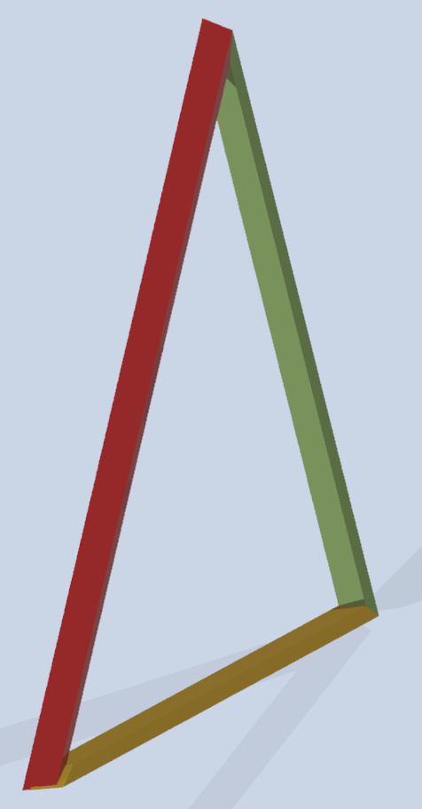
If we take a look at the face 1, which is assembled with three different struts A,B,C, this is what i get in CAD, after cutting the struts with the given angles and dimensions:

face 1 ABC.pngface 1 ABC-1.pngface 1 ABC-2.png

As i wrote earlier, i dont think that the problem is in my end, but as i also said i could be wrong heheh :) . I have noticed that the calculator gives weird dimensions, f.ex: strut a, its not possible to have  12.8 degree angle, and only 9mm length (Strut A, left side).

and here is the struts A,B,C from the acidome calculator:

ABC struts.png

And face diagram from acidome calculator:
face 1.png

Any idea how i could fix it, or perhaps a better calculator that i havent found out yet? The reason im using this one because its the only one ive seen so far which offers calculations based without hubs..


Thanks in advance !

RC

unread,
Nov 7, 2022, 6:57:23 AM11/7/22
to Geodesic Help Group
Here's what's causing problems with your model.  The drawing below shows cross-sections of a triangle.  Your model method is shown in the top sketch.  The conventional method is shown in the sketch below.

triangle cross-section.PNG

Norris

unread,
Nov 7, 2022, 7:53:32 AM11/7/22
to Geodesic Help Group
Thanks for the reply RC, im not sure im fallowing you though.
Do you mean i read the drawings from the calculator wrong ?

f.ex the strut G from the calculator:
strut G.png
and strut G in inventor:
strut g inventor.png

strut g inventor 1.png
strut g inventor 2.png

RC

unread,
Nov 7, 2022, 8:52:34 AM11/7/22
to Geodesic Help Group
If all three dihedral angles along the sides were the same, then it would all fit together perfectly.  But, because they are different and the boards tilt to create that dihedral angle, the ends will always misalign slightly.  It's like doing crown molding. If one board is angled between the wall and ceiling differently than the other piece, no matter how carefully you cut the angles they will never align properly.
The two boards below have dihedral angles of 30 degrees and 40 degrees. Both are 2x4's, but their ends will never be made to line up.

view03.JPGview02.JPGview01.JPG

Norris

unread,
Nov 7, 2022, 9:28:38 AM11/7/22
to Geodesic Help Group
That i understand, but the dihedral angle difference is 0.01, and i dont think that 0.01 deegre difference would make such a big impact as im having right now.
I dont want to ask You this question, but i will anyway, if You have time, could you just try and assemble one triangle from 3 struts and see if you get the same results ? 3struts.png
strutsghi.png
triangle ghi.png


Robert Clark

unread,
Nov 7, 2022, 9:31:42 AM11/7/22
to geodes...@googlegroups.com
Later, during my lunch break I will try to model it in Solidworks from the information you provided.

--
--
You received this message because you are subscribed to the "Geodesic Help" Google Group
--
To unsubscribe from this group, send email to GeodesicHelp...@googlegroups.com
--
To post to this group, send email to geodes...@googlegroups.com
--
For more options, visit http://groups.google.com/group/geodesichelp?hl=en

---
You received this message because you are subscribed to a topic in the Google Groups "Geodesic Help Group" group.
To unsubscribe from this topic, visit https://groups.google.com/d/topic/geodesichelp/MxTU6Pl1Sc8/unsubscribe.
To unsubscribe from this group and all its topics, send an email to geodesichelp...@googlegroups.com.
To view this discussion on the web visit https://groups.google.com/d/msgid/geodesichelp/67677c1b-4bae-4ee8-9a9e-2849d00ca84an%40googlegroups.com.

RC

unread,
Nov 7, 2022, 9:32:17 AM11/7/22
to Geodesic Help Group
Later, during my lunch break I will try to model it in Solidworks from the information provided.

Norris

unread,
Nov 7, 2022, 9:39:15 AM11/7/22
to Geodesic Help Group
Allright ! take Your time, ill be around :)

RC

unread,
Nov 7, 2022, 1:20:47 PM11/7/22
to Geodesic Help Group
The problem appears to be with the calculator.  There is very little precision in the lengths.  They are all rounded off to the nearest millimeter.  The angle accuracy is only to a tenth of a degree.  It is not clear if one should be using the degree measurement or the length measurement.  Also, mirror parts that should be identical in length, differ by a millimeter.
I would try to find a better online calculator.

triangle GHI.JPGtriangle corner GHI.JPG

Norris

unread,
Nov 8, 2022, 1:05:18 AM11/8/22
to Geodesic Help Group
Thats what i though.. Thank You for your time RC, appreciate it. Off to find something a better calculator i guess ...
Reply all
Reply to author
Forward
0 new messages