please help with a verilog programm

231 views
Skip to first unread message

Pablo Meraz

unread,
Feb 7, 2021, 3:12:15 AM2/7/21
to FPGAwars: explorando el lado libre

Dear Friends:

I have read something about verilog and I really like electronics, but I have no experience with Verilog. I have an ICE40- HX8K - Breakout Board card.

 I have been working on a large project and it is not working for me. When doing various tests, I found a strange error in an always block. I removed several lines of code to make it as simple as possible but where the error can still be detected

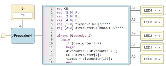
 The module runs activated by a clock with a prescaler of N = 22 to produce a very low frequency, this clock activates a counter from 0 to 7, when it reaches the value of 7, by code it is no longer increased. When the counter goes through binary 101, register C3 is activated and when the counter reaches 111, register C4 is activated.

 Additionally CY = C3 | C4, which must be activated whether C3 or C4 is activated

 The program is as follows:

01 reg CE;

02 reg [2:0] A;

03 reg [2:0] B;

04 reg [4:0] F;

05 reg [1:0] tiempo=2'b00;//****

06 reg [2:0] divcounter=4'b0000; //****

07

08 always @(posedge i)

09  begin

10    if (divcounter !=7)

11     begin

12    divcounter = divcounter + 1;

13     CE = divcounter[2];

14    tiempo = divcounter[1:0];

15   end

16   end

17

18 reg C3=1'b0; //**

19 reg C4=1'b0; //**

20 reg CY;

21

22 always @(*) begin

23  C3= (CE==1) & (tiempo==2'b01);

24  C4= (CE==1) & (tiempo==2'b11);

25  CY=C3 | C4; 

26  end

27

28 always @(posedge CY) begin

29     F[4]=CY;

30     F[3]=C3;

31     F[2]=C4;

32     F[1]=0;

33     F[0]=1;

34     end

35

36 assign A4=F[4];

37 assign A3=F[3];

38 assign A2=F[2];

39 assign A1=F[1];

40 assign A0=F[0];

 imagen.jpg

According to me, when executing the always @ (posedge CY) block the CY register should be true. 
CY becomes 1 when the counter is 101 (5) and when it is 111 (7).
I store in the F register the state of CY, C3 and C4 and indeed C3 = 0, C4 = 1 which should be like this, CY must be worth 1, but has the value of zero 
Curiously, if I don't initialize any of the registers on lines 5, 6, 18 or 19 that are "time", "divcounter", "C3" or "C4" the program works correctly.
In this case this failure is irrelevant, since the block does not need to evaluate CY as it is supposed to be true, but in the largest version I have, it also fails with other registers that should be on but when evaluating them in the block they always seem false.I would be very grateful if you could help me by indicating what is wrong in the program    

Alexandre Dumont

unread,
Feb 7, 2021, 12:33:43 PM2/7/21
to FPGAwars: explorando el lado libre
I would suggest you try to create a testbench module in Verilog to stimulate your module, and use iverilog and gtkwave to inspect the generated waveform. That should help you figure what is wrong with it.that is a very good exercise, and it will always help you. 

Also, In always blocks that are clocked (posedge), you should better use non blocking assignment (<= instead of =). 

Iverilog and also verilator (using the lint only option) can also help you find things that are not best practice. One that I remember is that your ref should be initialized (and in an lattice ice40hx-8k, iirc you can only initialize to 0,but it's best to specify it anyway, otherwise you don't know what the signal will really be). 

Jorge Garcia Mateos

unread,
Feb 7, 2021, 2:30:08 PM2/7/21
to fpga-wars-explora...@googlegroups.com

Hi Pablo, the Alexandre's advice to use a testbench is great and will give you more control and capability to check your code by yourself. You have to install "gtkwave", if you use icestudio you have "iverilog" installed. I've rewritten your code as:

module test 
    (input i, 
     output A0,A1,A2,A3,A4);
reg CE = 0;
reg [4:0] F = 0;
reg [1:0] tiempo = 2'b00;//****
reg [2:0] divcounter = 4'b0000//****
reg C3 = 1'b0//**
reg C4 = 1'b0//**
reg CY = 1'b0;
always @(posedge i)
    begin
        if (divcounter !=7)
            begin
                divcounter = divcounter + 1;
                CE = divcounter[2];
                tiempo = divcounter[1:0];
            end
    end
always @(*) 
    begin
        C3 = (CE==1) & (tiempo==2'b01);
        C4 = (CE==1) & (tiempo==2'b11);
        CY = C3 | C4; 
    end
always @(posedge CY) 
    begin
        F[4] = CY;
        F[3] = C3;
        F[2] = C4;
        F[1] = 0;
        F[0] = 1;
    end
assign A4 = F[4];
assign A3 = F[3];
assign A2 = F[2];
assign A1 = F[1];
assign A0 = F[0];
endmodule

and made a testbench "test_tb.v" for it:

module test_tb ();
//-- Registro para generar la señal de reloj
reg clk = 0;
//-- Generador de reloj. Periodo 2 unidades
always #1 clk = ~clk;
//-- Instanciar el componente
test  dut(clk,A0,A1,A2,A3,A4);
//-- Proceso al inicio
initial begin
    //-- Fichero donde almacenar los resultados
    $dumpfile("test_tb.vcd");
    $dumpvars(0, test_tb);
    # 20 $display("FIN de la simulacion"); $finish; //20 units of time are enough since after divcounter=7 nothing changes
end
endmodule

With that testbench you could see all the variables of your code on gtkwave.

To run the simulation, make sure than iverilog, vvp (also installed with icestudio) and gtkwave are in your path.
In command line in Windows:
```
iverilog -o test_tb.out test_tb.v test.v
vvp test_tb.out
gtkwave test_tb.vcd
```
In command line in linux, very similar:
```
iverilog test.v  test_tb.v -o test_tb.out
./test_tb.out
gtkwave test_tb.vcd
```
I attach you the cronogram obtained with gtkwave. It seems that C3 has a value of 1 at divcounter=101, but changes again to 0 in the next positive edge of the input clock because "tiempo" becomes "10" and is not "01" anymore. I don't know if this is what you want, anyway you have now more tools to debug your code.

On the other hand, I see that you are using in your design two different clocks, the clock of the fpga for the prescaler and the output of the prescaler as input clock for the part we are debugging. That is not a very good practice, it's better only one clock for everything. As Obijuan says "Un único reloj para dominarlos a todos". I recommend you to read the chapter of ["Reglas de diseño síncrono"](https://github.com/Obijuan/open-fpga-verilog-tutorial/wiki/Cap%C3%ADtulo-22%3A-Reglas-de-dise%C3%B1o-s%C3%ADncrono) of the obijuan's verilog tutorial (in Spanish). There you will find ways to use only one clock for the full  design. Ok, more work but more you learn ;-)

Hope it helps.

Best regards,

Jorge
--
Has recibido este mensaje porque estás suscrito al grupo "FPGAwars: explorando el lado libre" de Grupos de Google.
Para cancelar la suscripción a este grupo y dejar de recibir sus mensajes, envía un correo electrónico a fpga-wars-explorando-el...@googlegroups.com.
Para ver esta conversación en el sitio web, visita https://groups.google.com/d/msgid/fpga-wars-explorando-el-lado-libre/ec7d2ba1-6bab-40c4-b349-ccac992996fen%40googlegroups.com.
cronogram.png

Alexandre Dumont

unread,
Feb 7, 2021, 2:45:38 PM2/7/21
to FPGAwars: explorando el lado libre
I was going to reply as well, but Jorge beat me to it ;).

Keeping your code, with CE and CY not initialized, and keeping the blocking assignments (CE, divcounter and tiempo) I get this waveform:. See how CE is unknown (red) at the beginning, as well as F untill divcounter is 5. CY is also behaving weird (not sure it's what you would expect), and as a consequence it will trigger twice the always(@posedge CY).

blocking.png

fixing the blocking assignments into non-blocking assignments, like this:

always @(posedge i)
 begin
   if (divcounter !=7)
    begin
   divcounter <= divcounter + 1;
    CE <= divcounter[2];
   tiempo <= divcounter[1:0];
  end
  end

and also in the last block:

always @(posedge CY) begin
    F[4]<=CY;
    F[3]<=C3;
    F[2]<=C4;
    F[1]<=0;
    F[0]<=1;
end

we now get this other waveform. Notice how both are very different:

non-bloking.png

I'm not really sure what is the behaviour you would expect.

I both cases anyway I notice that F[4] is 1, so I'm not sure what you problem would be. (I haven't tried it in an FPGA). 

Do you have any reg (in other part of your code that you didn't share with us) that you maybe initialize to something not 0? In Lattice ice40 you have to initialize to 0, and then later change to another value.

Hope that help a little bit even if that doesnt' give you an answer...

Alexandre Dumont

unread,
Feb 7, 2021, 2:56:05 PM2/7/21
to FPGAwars: explorando el lado libre
Oh btw, the first I did when I took your code (after embedding it in a module) was running verilator --lint-only. I think it's always a good idea to use that as it can spot some unintended mistakes:

~/tmp/bench$ verilator --lint-only  top.v
%Warning-WIDTH: top.v:15:22: Operator ASSIGN expects 3 bits on the Assign RHS, but Assign RHS's CONST '4'h0' generates 4 bits.
                           : ... In instance top
   15 | reg [2:0] divcounter=4'b0000;  
      |                      ^~~~~~~
                ... Use "/* verilator lint_off WIDTH */" and lint_on around source to disable this message.
%Error: Exiting due to 1 warning(s)


~/tmp/bench$ verilator -Wall --lint-only  top.v
%Warning-UNUSED: top.v:13:11: Signal is not driven, nor used: 'B'
                            : ... In instance top
   13 | reg [2:0] B;
      |           ^
%Warning-BLKSEQ: top.v:21:15: Blocking assignments (=) in sequential (flop or latch) block
                            : ... Suggest delayed assignments (<=)
   21 |    divcounter = divcounter + 1;
      |               ^
%Warning-BLKSEQ: top.v:38:9: Blocking assignments (=) in sequential (flop or latch) block
                           : ... Suggest delayed assignments (<=)
   38 |     F[4]=CY;
      |         ^
%Error: Exiting due to 4 warning(s)


:)

Alexandre Dumont

unread,
Feb 7, 2021, 3:07:59 PM2/7/21
to FPGAwars: explorando el lado libre
If you still keep having problem with synthesis behaving differently from simulation, maybe have a look at this article by Dan Gisselquist (zipcpu): Reasons why Synthesis might not match Simulation. (Dan's website is VERY good)

Eduardo Rodríguez

unread,
Feb 7, 2021, 3:54:25 PM2/7/21
to FPGAwars: explorando el lado libre

Jorge García Mateos

unread,
Feb 7, 2021, 5:22:40 PM2/7/21
to FPGAwars: explorando el lado libre
Thanks a lot for the references to the killing "blocking-nonblocking" dilema and for the link to the website of Dan, I'll read carefully that info.
An strange thing I've found: when you don't initialize to value 0 the variables "CE" y "CY" the simulation with verilog doesn't work properly (as showed by the cronograph of Alexandre) and verilator pops warnings. Initializing to zero those values the problems disaper and everything seems ok. But when running "yosys" there are warnings indicating that those variables have an unprocessed 'init' value. It seems that yosys is more happy when you don't initialize the variables :-D
warning.png

Alexandre Dumont

unread,
Feb 7, 2021, 5:53:34 PM2/7/21
to FPGAwars: explorando el lado libre
Hum, with regard to the warnings... I've found this comment by Clifford Wolf:


And what I understand is that it's triggered by the register is initialized, but used in a combinational always @(*) block. (the reg will always have a value, so it never need to be initialized). 

So my understanding (now, after reading that comment) is that we should initialize to 0 regs that are used in clocked blocks, but it's not necessary ( it's even ignored/unprocessed by yosys) when used in a combinational block. Interesting, I didn't know that (never payed attention to such a warning to be honest). 


--
Has recibido este mensaje porque estás suscrito a un tema del grupo "FPGAwars: explorando el lado libre" de Grupos de Google.
Para cancelar la suscripción a este tema, visita https://groups.google.com/d/topic/fpga-wars-explorando-el-lado-libre/XNxr1KauHv0/unsubscribe.
Para cancelar la suscripción a este grupo y a todos sus temas, envía un correo electrónico a fpga-wars-explorando-el...@googlegroups.com.
Para ver esta conversación en el sitio web, visita https://groups.google.com/d/msgid/fpga-wars-explorando-el-lado-libre/34c15ef0-cddd-4f06-9218-c47eb7673e02n%40googlegroups.com.

Jorge Garcia Mateos

unread,
Feb 7, 2021, 6:17:33 PM2/7/21
to fpga-wars-explora...@googlegroups.com

It has sense. Thanks!

Has recibido este mensaje porque estás suscrito al grupo "FPGAwars: explorando el lado libre" de Grupos de Google.
Para cancelar la suscripción a este grupo y dejar de recibir sus mensajes, envía un correo electrónico a fpga-wars-explorando-el...@googlegroups.com.
Para ver esta conversación en el sitio web, visita https://groups.google.com/d/msgid/fpga-wars-explorando-el-lado-libre/CALTA55H3i%3Dxvskm%2B6SPM2afQHDCj0OGNaPWVz4Uvis6%2BXBbyag%40mail.gmail.com.

Pablo Meraz

unread,
Feb 7, 2021, 10:44:52 PM2/7/21
to FPGAwars: explorando el lado libre

Thank you very much adumont for your recommendations

Indeed, it had not occurred to me to use specific versions of Verilog, I just downloaded the ICE Studio and began to experiment. from your recommendation and others I see that there are many possibilities.

precisely in the debug part I have had serious problems because what my code generates is transferred to a card and the only thing I can see is the final result seen in some LEDs. If I ran a simulator that generates the waveform, it would be fabulous. (I'll experiment with the recommended programs).

Indeed, I knew that in the always @ (posedge) the blocking form  = must not be used, instead <= but I was experimenting and all the tests I did seem that the blocking mode works, that is, it performs the instructions sequentially as I need them. but that being bad practice, I won't use it anymore.

In your second comment, perfect the time diagram, that's why I prefer to start the registers so that they do not have indeterminate values.

The behavior of CY is as expected by me, since it must be activated with C3 or C4 and since C3 is activated first and then C4, it is fine for CY to activate twice.

When you change the = to <= it produces results that are not what I expected, since all the instructions are executed simultaneously and not sequentially. I need them to be sequential, that's why I'm seeing that I'm going to have to rethink the writing of the program.

The program I sent is all I have, there are no other hidden registers. (I have another version of the program that is much larger, but I was eliminating lines but verifying that it always produced the error).

On your first run CY ends up being worth 1, that's what I need, but when I run it on my card CY ends up being worth 0.

Dear Jorge García Mateos, thank you very much for your comments, you definitely show some tools that are very powerful and that I am not using. I see in the time diagram (attached image) that A5 actually ends up taking the value of 1, in my tests A5 ends up being 0 and then I see that it may be something related to my card or the version of the programs I have. With the suggested time diagrams any doubt is clarified, they are perfect.

effectively "tiempo" should be taking the values ​​00, 01, 10, 11, 00, 01 etc. actually the combination of CE + tiempo is the same as divcounter.

Really, I think that having two clocks can be confusing, I am going to redesign the program to work with only one clock. I definitely think it's better although I'm afraid I'm probably going to spend extra cycles. Thanks for the recommended reading !!!


Thanks to Rodriguez Campos Eduardo, I am going to review the suggested material.

Again, thank you all very much, you were very kind in answering my question, I learned a lot from your recommendations, I am going to install the simulators and read all the recommended material
Reply all
Reply to author
Forward
0 new messages