Interfacing FLIR Lepton I2C with Intel Edison 1V8 Logic Level

McRender
Has anyone succeeded accessing the FLIR Lepton over I2C (SCL/SDA) through a logic level translation? I am not able to get an ACK over the I2C bus from my Lepton when using the Intel Edison as a host (master). My setup is as follows:
- Intel
Eidson on mini breakout board
- Using
I2C1_SDA (GP20) & I2C1_SCL (GP19)
- Pullmode
of both I2C pins are disabled by SoC
- Using
of an external 5K Ohm pullup resistor on the lower level logic (Edison 1V8)
- Using
of an external 5K Ohm pullup resistor on the higher level logic (FLIR Lepton
3V3 input voltage)
- Using
of an Adafruit 4-C BI-Directional level shifter (http://www.adafruit.com/product/757)
- Setting the I2C speed to 100 KHz (STD)
- Raspberry
PI B+
- Using
I2C1_SDA (GP8) & I2C1_SCL (GP9)
- Using
of the internal 4.7K Ohm pullup resistors
- Using the default I2C speed of 100 KHz
As
far as I am using the Raspberry PI setup, everything works like a charm. I have
enabled I2C and used the default bus speed of 100 KHz. By executing “i2cdetect –y –r 1” and measuring the
signals with my RIGOL DS1052E on the SCL pin yields to the following image:
One
can clearly see sharp edges and values that fit to the I2C standard. As a
return value of i2cdetect the FLIR
Lepton get listed with the address 0x2A. Further I can make use of the Lepton
SDK to read out status registers and perform a flat field correction (FFT)
without any errors.
When
I am using the Intel Edison the situation changes. For debugging purpose I’ve
measured all the signals on the I2C bus and tried to stepwise include parts of
the electronic circuit. As a starting point I’ve measured the signal on the SCL
pin without the connection to the level shifter:

Again
one can see not so sharp edges but values that fit to the I2C standard too. The
edges and the signal LOW/HIGH value depends on the used pullup resistor. I’ve
been playing with different values here and ended up by using a 5K Ohm
resistor.
As
a next step I have included the level shifter and connected the lower side with
the 1V8 pin and the higher side with the 3V3 pin of the Edison. SCL on the higher
side is also pulled up with a 5K Ohm resistor. Measuring this time on the
higher logic level side of the SCL line yields to the signal in the next image:

So
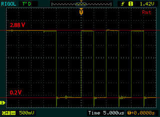
far so good. When I now include the FLIR Lepton and measuring the signal on the
3V3 logic level side I’ve got the following strange image:

It
seems that the signal can’t reach anymore the voltage of a logic LOW. Another
observation is the measured current (5.3mA) that flows through the SCL pin of
the LEPTIN. Is this supposed to happen? It looks like the input has an internal
resistor of about 528 Ohms (2.8V/0.0053A). I am also a bit confused about the
2V8 IO voltage of the Lepton and the breakout board from Pure Engineering. Shouldn’t there be a connector that let me connect the 2V8 IO voltage as the higher voltage of the level shifter? Could this be the problem with the shifting?
Please
let me know if you have or have not successfully connected your Lepton to
another logic level. I would also appreciate if you have any hints on how I could
solve my issue here.
Thank
you very much in advance…
McRender

Edison SCL pin 1V8 lower logic side

Edison SCL pin 3V3 higher logic side

Cyrill
Btw: I am using the Intel Edison Arduino breakout board with additional external pullups as stated in the lepton data brief (page 6 / note 1).
Seems like a systematic issue!? Or what do we overlook?
McRender

Isaac Clayton
McRender
Isaac Clayton

