Delta robot ball joints
3,044 views
Skip to first unread message

Michael Stegen
Oct 2, 2014, 6:03:04 PM10/2/14
to fire...@googlegroups.com
As we know the current Traxxis or MPJET ball links bind, when moving the end effector outside of the chassis of the FPD.
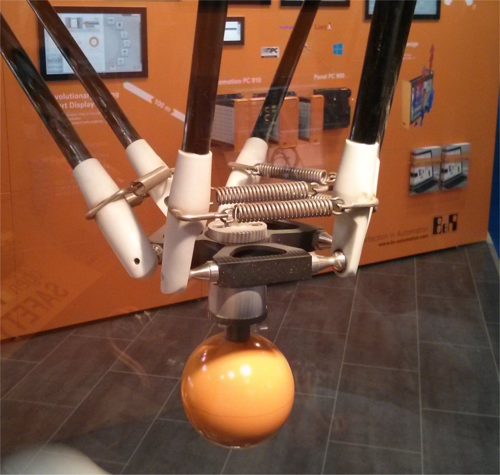

I attended a exhibition yesterday where they had quite a few professional delta robots.
What i noticed on these machines, is that they also had two springs on each end of the arms, just like on Neils FPD.
When I asked if they were used to remove backlash, they told me that they are used to keep the arms pressed onto the balls!
This had never occurred to me, as being an option.
In other words, they are used to keep everything together.
if you pull on the arm, you can take it apart completely, without damaging the joint.
Here's a picture i took:
This might make things much easier for us.
Just 3D print a couple of rod ends with holes in them to hold a steel ball, glue a M3 (hex)bolt to a steel ball, and you end up with something like this:
Obviously the rubber band needs to be replaced with two springs.
The above picture was made with some leftover pieces of carbon tube, but i've got more on order so i will try this asap.
Btw, the steel balls are rom Robotdigg, they are not perfect, but good enough i think.

Karl
Oct 2, 2014, 7:14:51 PM10/2/14
to fire...@googlegroups.com
That's a great idea Mike!
Wow. :)

Michael Anton
Oct 2, 2014, 9:56:16 PM10/2/14
to fire...@googlegroups.com
That does look pretty good. I noticed in the commercial version, that the cup ends are offset to put the arms pointing straight at the balls. I wonder if there is a reason for that? It looks like your design would be easy to change if it is important.
Is there a reason that the arms are so far away from the center of the end effector? I'm thinking that if the arms were closer to the middle, that the overall head size would be smaller, allowing it to get closer to obstructions. I think it would make is slightly stiffer as well.
Mike

Neil Jansen
Oct 3, 2014, 9:54:48 AM10/3/14
to Michael Anton, fire...@googlegroups.com
Is there a reason that the arms are so far away from the center of the end effector? I'm thinking that if the arms were closer to the middle, that the overall head size would be smaller, allowing it to get closer to obstructions. I think it would make is slightly stiffer as well.
Yes, rigidity. The entire delta mechanism is a balancing act between lots of different factors: accuracy, speed, rigidity, work area, zones where things "bind up" and collide (not a good thing), and is obviously influenced by what ratios that the delta mechanism "wants" to be at. For example, there's a certain ratio between the parallel carbon rod lengths and the orange printed arm lengths, that's optimal. I found that ratio through lots of work, and if you start changing things, you'll start to have other problems. I do have a new ball-stud and magnet version coming very soon, that has different ratios, but there are lots of other things needed to get that design fully working, and will be lots of trial and error before it's done. I do think it will be superior to what we have now, and won't bind up (especially when homing, you'll notice the current one will have the rods hit the big gears... that will be fixed as well).
As for Mike's original OP post. That's how either the ABB FlexPicker or Adept Quattro did it (can't remember which). Makes cleaning and whatnot really easy. it would certainly be cheaper than my version with magnets, because 12 magnets cost more than six springs. However, we've got to make sure that having the things on both sides like that doesn't cause it to bind up... so yea, we've got some work to do still :) I really like the idea and will try to do something like that if it's possible.
Thanks Mike! (and Mike)
--You received this message because you are subscribed to the Google Groups "FirePick" group.
To unsubscribe from this group and stop receiving emails from it, send an email to firepick+u...@googlegroups.com.
To post to this group, send email to fire...@googlegroups.com.
Visit this group at http://groups.google.com/group/firepick.
For more options, visit https://groups.google.com/d/optout.

DAniel Dumitru
Oct 5, 2014, 3:27:37 AM10/5/14
to fire...@googlegroups.com
Hello all,
I would like to start to build my machine.
I can get easy some Alu Extrusions for frame of 30X30mm.
As far as I seen I have to modify the lower plate.
What do you think ? This would be the only change that needs to be made ?
Kind REgards,
Daniel
I would like to start to build my machine.
I can get easy some Alu Extrusions for frame of 30X30mm.
As far as I seen I have to modify the lower plate.
What do you think ? This would be the only change that needs to be made ?
Kind REgards,
Daniel
Michael Anton
Oct 5, 2014, 3:48:46 AM10/5/14
to fire...@googlegroups.com
You would need to modify the lower plate, the upper plate, and anything that mounts to the frame, like the feeders. Do the 30x30mm extrusions have the same slot width, and depth? If they don't, you may need to use different nuts for the extrusions, and the hardware to fasten to them may be different as well.
Mike
DAniel Dumitru
Oct 5, 2014, 7:38:02 AM10/5/14
to fire...@googlegroups.com
Pretty much to change.
What tool was used to design this mechanical part ? I hope that was not SolidWorks since I don't have such a license.
Br,
DAniel
What tool was used to design this mechanical part ? I hope that was not SolidWorks since I don't have such a license.
Br,
DAniel
--
Neil Jansen
Oct 5, 2014, 10:14:09 AM10/5/14
to DAniel Dumitru, fire...@googlegroups.com
Daniel,
A lot of the questions that you are asking can be answered in the README files that are prominently displayed in our github repository, right beside the mechanical files and other source files:
https://github.com/firepick-delta/firepick-delta
https://github.com/firepick-delta/firepick-delta/tree/dev/mechanical
(That will answer your question on what cad software we use)
Karl Lew
Oct 5, 2014, 10:25:23 AM10/5/14
to Neil Jansen, DAniel Dumitru, fire...@googlegroups.com
Daniel,
Are the 20x20mm extrusions not available to you from Misumi?
We chose Misumi for its global availability. Please tell us more about your situation and why you are considering 30x30mm. It's important for us to understand global supply circumstances.
Thanks,
Karl
Michael Stegen
Oct 5, 2014, 7:36:24 PM10/5/14
to fire...@googlegroups.com
Update:

The bolt is just there to hold the spring in place, it's not screwed into anything.


The arms can be disconnected in seconds...
Printed some rod ends for 6mm rods/tubes (rod length 256 mm). As i did not want to wait till my carbon tubes showed up, i used aluminium tubes for now.
After some iterations, i eventually settled with seperate ones for each end. They can hold 1 or 2 springs per rod end. I used two springs at first, but one spring in the middle also seems to do the job.
It does not bind up any more, and moves really smooth.
As my end effector and arms were already modified slightly (they have a M3 nut trap on the inside), i could just screw the 10mm hex bolt into it, and then glue a 9,5mm steel ball (robotdigg) onto it with superglue.
The only thing left to do is to print three modified pulleys, as the belt tensioner is now the limiting factor when moving the end effector.
Not looking forward to take the whole thing apart again, but that will hopefully be the last modification to the mechanism. That's why it's an Alpha i guess ;-)
The bolt is just there to hold the spring in place, it's not screwed into anything.
The springs at the top can not be beween the rods when homing, so i moved them a bit higher.
The arms can be disconnected in seconds...
If anyone want's to test this setup on their own machine, here are the Cubify Design files and STL's of the rod ends:
Neil Jansen
Oct 5, 2014, 8:02:59 PM10/5/14
to Michael Stegen, fire...@googlegroups.com
Mike,
Those look awesome! I'm going to start printing them out tonight and give them a try. I have two sets of custom ballstuds: http://static.squarespace.com/static/53c16638e4b0fb85d41808ab/53c71867e4b04b94d4ca05a5/53c718e4e4b04b94d4ca0680/1405557006845/IMG_6883.png .. I've also got a pretty good sprint assortment kit that I picked up a while back.
Those look awesome! I'm going to start printing them out tonight and give them a try. I have two sets of custom ballstuds: http://static.squarespace.com/static/53c16638e4b0fb85d41808ab/53c71867e4b04b94d4ca05a5/53c718e4e4b04b94d4ca0680/1405557006845/IMG_6883.png .. I've also got a pretty good sprint assortment kit that I picked up a while back.
Thanks,
Neil
Neil
Michael Stegen
Oct 5, 2014, 8:56:02 PM10/5/14
to Neil Jansen, fire...@googlegroups.com
Great!
It's nice to help a bit and make FPD better.
The spring i used was part # T190 from www.alcomex.nl , but expensive.
A better alternative would probably be Farnell, who now sells a kit http://nl.farnell.com/duratool/d01893/spring-set-200pcs/dp/2444377 for Eur 5,- with various sizes and lengths.
Those ballstuds look very nice, are those spot welded?
This might also be an option for other people: http://deltaprintr.com/shop/hardware/10mm-diameter-steel-balls/
I did notice that superglue has it's limits, i tried srcewing a bolt with glued on ball, onto the end effector, which had a M3 nyloc nut.
The first attempt worked fine, but on the second bolt, the glue was not strong enough. So i decided to fit the bolts first, and then glue the ball on.
Neil Jansen
Oct 5, 2014, 9:04:58 PM10/5/14
to Michael Stegen, fire...@googlegroups.com
The ballstuds in that photo were TIG welded. There are Chinese factories that will make them cheaply (either electrically spot-welded, or machined), but you have to buy them in quantity. Alternatively, I could build a pretty cheap spot-welding setup using a drill press, a machined jig, and a microwave oven transformer (rewound with 1/0 AWG wire -- not sure what the european equivalent of American wire gauge, but it's like thick rope). If I did that, I could make hundreds or thousands of them pretty easily. My springs were from a company in the USA called Harbor Freight, everything in the entire store is cheap Chinese stuff. I payed a few US dollars for hundreds of springs in a little plastic box. Luckily since we don't need a "precision" spring, it should be pretty easy to substitute and find one that's close enough, as long as it holds them together.
One other thing, would you be able to send the AD_PRT of your modified 3D0002 pulley? I like yours a lot more and will likely add that to the main repo.. with attribution/credit to you, of course.
Thanks,
Neil

Joshua Pritt
Oct 5, 2014, 9:20:38 PM10/5/14
to Neil Jansen, Michael Stegen, fire...@googlegroups.com
Does the spring constant for those springs matter? I mean is there such a thing as too much or too strong a spring that would change the way or speed it moves?
DAniel Dumitru
Oct 6, 2014, 1:05:17 AM10/6/14
to fire...@googlegroups.com
Hello Karl,
I really appreciate your concerns related to global availability of
components for this project.
It's just I have a friend that can offer me for free those profiles.
Since I don't want to get out from group I am seriously thinking to
stick on Misumi.
Thank you,
Daniel
I really appreciate your concerns related to global availability of
components for this project.
It's just I have a friend that can offer me for free those profiles.
Since I don't want to get out from group I am seriously thinking to
stick on Misumi.
Thank you,
Daniel
DAniel Dumitru
Oct 6, 2014, 1:39:38 AM10/6/14
to Neil Jansen, fire...@googlegroups.com
Hello Neil,
Thank you for details. Indeed I should have been reading documentation
but I have preferred to start a discussion.
You are absolutely right regarding time for redesign versus buy Misumi.
I will have a look and let you know.
Kind REgards,
DAniel
Thank you for details. Indeed I should have been reading documentation
but I have preferred to start a discussion.
You are absolutely right regarding time for redesign versus buy Misumi.
I will have a look and let you know.
Kind REgards,
DAniel
Karl Lew
Oct 6, 2014, 2:19:34 AM10/6/14
to DAniel Dumitru, fire...@googlegroups.com
Daniel,
Thanks for the clarification and apologies for the extra expense. The 30x30 is stronger but you would have to modify connecting parts. We might revisit extrusion dimensions later if there are issues with rigidity, but so far the 20x20 is perfect.
Note that if you have 3d printer, you can save money by printing the 3D0051 brackets instead of buying Misumi brackets.
Cheers,
Karl
--
You received this message because you are subscribed to the Google Groups "FirePick" group.
To unsubscribe from this group and stop receiving emails from it, send an email to firepick+u...@googlegroups.com.
To post to this group, send email to fire...@googlegroups.com.
Visit this group at http://groups.google.com/group/firepick.
For more options, visit https://groups.google.com/d/optout.
Michael Stegen
Oct 6, 2014, 8:37:16 AM10/6/14
to Joshua Pritt, Neil Jansen, fire...@googlegroups.com
I don't think the tension on the springs matters much, it might create some more wear on printed plastic rod ends, but the balls are very smooth, so it will be minimal.
Neil, here are the modified pulley, arm, and limit switch Cubify design files.
You will have to take a look at the pulley's design's constraints (for the belt stop), as i didn't know how to set these up, and removed them..

ICEC
Oct 6, 2014, 7:32:32 PM10/6/14
to fire...@googlegroups.com
Nice work Mike ,
And I was so happy I finaly made it to print some parts and had 2 of the 3 pulley already printed, seems like ill be reprinting those
When your carbon rods arrive, will you keep using these ?
The Pulley is the only thing that gets changed from the current github desgn right ?
Thanks,
Hopefully mine starts forming soon, gathering a few parts at a time
Mike Stegen
Oct 7, 2014, 3:26:31 AM10/7/14
to fire...@googlegroups.com
I think it's best to reprint the pulleys, even with the normal traxxis joints you will see some benefit.
If you want to go with the ballstuds + printed ball joints, they you will also have to modify the arms, end effector, and interrupter.
As i added nut traps in those parts.
ICEC
Oct 7, 2014, 2:27:27 PM10/7/14
to fire...@googlegroups.com
Ok , so i thouth a picture would give the best vieuw, so here is what i already got

1x 8mm Clear Acrilyc Bottom plate, Top one i though ill wait a bit so ill get all the necessary holes
6x 3D0001 608 Bearing block .
6x 3D0003 Delta arm 90mm
2 of 3 3D0002 Pulley will need a reprint of all 3 with the modified one of Mike
3x 3D0004 and 3D0005 are beeing printed, should be ready by tomorrow
Ballstuds + printed ball joints I liked the design so ill go with that one indeed,
Ive seen you used a different end effector indeed , but i also see that yours is not for modular tool setup if im correct , but one head ( smt pick) only.
So ill have to modify the end modular effector to fit , still have to figure out the differnces . maybe someone is already on changing that ?
Wich arms do you mean need to get modified ? - hope its not the ones I already have printed :p
Ill be doing a robotdigg order by next week i think, also the extrusions ill order in coming week (verry bussy at the moment)
But I really like the bull stud design , so ill will be trying that
I have a few weeks to go still before i have anything that capable of moving , but ill get there
Hoping the EMC01 board is gonna be working and end rev by a few weeks so I can try to build one too, or order is from someone here if thats possible
Neil Jansen
Oct 7, 2014, 2:38:32 PM10/7/14
to ICEC, fire...@googlegroups.com
Looks great so far!
The parts you have printed will work great with the specified Traxxas 5347 (or equivalent) rod ends. The modular end effector (the one in github) will need six rare earth magnets to make the tools interchangeable. Mike's integrated design is non-interchangeable, only for pick and place. You could also use the github one and just run some self-tapping screws through it to hold it together, or glue, if you can't find the right magnets :) I plan to supply and sell the correct-size magnets (and other hard-to-find parts), and I'll try to get these into some distribution channel, via fulfillment service, so that they can be purchased in Europe and other parts of the world... If you can only find other magnet sizes, you could always modify the original CAD files, or maybe someone on this mailing list can help you.
The ball-stud design will require printing new arms and end effector, and the spring-cup pieces that go on the arm. Karl and I have been looking around for ballstuds on the internet, and other ways to fabricate them. We'll hopefully get some info in the coming days ahead. I've printed Mike's ball-and-spring design and really like it so far... but need to have some more time to play with it and run accuracy tests.
I would recommend printing Mike's version of the pulley, regardless of which arm-joint design you use. I will have that checked into github probably tonight, with STL's provided, along with the ballstud parts.
Keep up the great work and send us more pics, as your build progresses :)
-Neil
--
ICEC
Oct 7, 2014, 3:21:18 PM10/7/14
to fire...@googlegroups.com, igorcon...@hotmail.com
Thanks for the info Neil, Indeed as the parts get together here I will post more pictures and info if someone asks for it , I am all into this opensource designing thing , just too cool to not be part of it :p
Just a few questions about the bull stud.
I realy liked the design so I want to try that out , saying that means i will not be using/ordering the Traxxas 5347 rod ends , but I will be making the printed ones with the spring. Will still need some balls ( robotdig maybe , ill try to get something better if I can)
If I get it correct , I will have to reprint the 6x 3D0003 Delta arms also again ?. Did Mike already make a modified version of the arms ? is it longer ??
also the modular end effector will need some modifications, for the balls.
For the magnets i haven't really looked into the end effector part good yet, wanted to make the top parts first then ill go to that part , but its approaching fast.
So i think i will be needing the magnets anyway, I do want to have an interchangable head , so I can 3d print + pick and place + dispense solder paste
Overall the Mike´s ball stud design should give a steadier endeffector right ? thats my though for now then. also does it give more movement in x-as ?
As for modifing the existing parts, Im at 98% finished of a building engineer, so im verry good at 2d painting ( autocad ) 3d stuff I cant do verry well,
but nothing I cant learn to do . But if there is someone else that can make the right mods in a flash , id say feel verry free to do so :p
Ill be folowing the progress here, So keep making those great post guys , lot of info in it
Igor
Neil Jansen
Oct 7, 2014, 3:38:53 PM10/7/14
to ICEC, fire...@googlegroups.com
Just a few questions about the bull stud.
I realy liked the design so I want to try that out , saying that means i will not be using/ordering the Traxxas 5347 rod ends , but I will be making the printed ones with the spring. Will still need some balls ( robotdig maybe , ill try to get something better if I can)
The ball-studs that I am using have been TIG-welded to M3 x 10mm socket-head cap screws (like the picture in a previous post). I have already had one of these break at the weld joints. Mike Stegen tried glueing them together, as i recall, but that doesn't sound very great for durability. There are places where you can buy them, but I'm not sure where to get these outside of the USA right now (we will start collecting all the places to buy them, on our Wiki page at http://github.com/firepick-delta/firepick-delta/wiki to help others out). So that's the only problem with this design right now... Where do you get the ballstuds from? :) We're still trying to figure this out :)
If I get it correct , I will have to reprint the 6x 3D0003 Delta arms also again ?. Did Mike already make a modified version of the arms ? is it longer ??
also the modular end effector will need some modifications, for the balls.
The main difference is that there are nut traps on them. And last night I made them thicker so that they're more rigid and don't flex. I haven't posted these files yet, but they should be up tonight.
Overall the Mike´s ball stud design should give a steadier endeffector right ? thats my though for now then. also does it give more movement in x-as ?
I believe so, yes, but I need more time to try them out and check for other problems.
Cheers,
Neil
Joshua Pritt
Oct 7, 2014, 4:13:07 PM10/7/14
to Neil Jansen, ICEC, fire...@googlegroups.com
Would it help if you chiseled or broke a tiny, flat edge off of the ball to make a better spot for the weld to "grab on"? I assume the weld didn't penetrate or melt the edge of the smooth ball enough to really bond. What about sanding a flat edge onto the ball? Or did you already do that first? Or does TIG welding already do such an intense heat that it should have melted enough of the ball to mix in and really bond?
ICEC
Oct 7, 2014, 5:22:54 PM10/7/14
to fire...@googlegroups.com, igorcon...@hotmail.com
Well for the ball studs ,
I googled a bit and found these , http://kmrcshop.com/products/HK852-8.5mm-Ball-Screw.html
i see they use them in rc cars, but I think ill go looking for them in the local hardware store before i try to order them online from a far away place :p
Bye the way , what size is the ball used now 5mm ?
Igor
Neil Jansen
Oct 7, 2014, 5:25:02 PM10/7/14
to ICEC, fire...@googlegroups.com
I'm using 3/8" ball-studs and I think that's also what Mike Stegen is using.
Karl and I found some 10mm ball-studs on the internet and those would work. Anything much smaller would possibly cause problems, and would need someone to make a version of the 3D files with the correct ball socket size.
ICEC
Oct 7, 2014, 5:33:56 PM10/7/14
to fire...@googlegroups.com, igorcon...@hotmail.com
Mike Stegen , as your also from the Netherlands
would you mind telling me where you got the ball studs from (local hardware ?).
or if your ordering them from overseas , is it possible you order a set for me too and we will arrange for me to get them (paying offcourse)
Michael Anton
Oct 8, 2014, 1:14:05 AM10/8/14
to fire...@googlegroups.com
Here is another one: https://www.youtube.com/watch?v=RM1ytIyH6BQ but done slightly differently. I'm not sure I completely like the concept of this one, but it is interesting none the less.
For your version, I wondered if we could just have another matching ball socket on the end effector, and just let the balls float. It might be difficult to make this work, without limiting the range of motion, but it would sure be nice and simple, and wouldn't require mounting that balls onto studs.
Mike
Karl
Oct 8, 2014, 10:44:31 AM10/8/14
to fire...@googlegroups.com
Oh. That IS clever!
What I like about this design is that the balls are on the rods. If you look at the human thigh bone, you'll notice that the ball is on the limb, not the hip. I'm guessing there are advantages to this, since I don't see a lot of species with the other arrangement. (Ok. Ok. Ok. I don't see any). So I would like to experiment with this variation on Mike's suggestion when I build my second FPD later this month.
It took me a while to see how the balls were held in place until I saw the white string. The white string is ingenious and problematic at the same time. It's nice that it's a single component (vs. two springs). It's nice that the enclosing sockets are passive 3Dprinted sockets. So this is a great way to make cheap, precise deltas. On the downside, changing the effector is a fumbling mess. If you detach the string, the arms fall down and getting them back on is a bit of a tricky "i need six hands and arms" exercise. Last night I watched Neil snap out the FPD effector in seconds using Mike's design. Re-assembly was equally quick.
Thanks for the link! I learned a lot.
Neil Jansen
Oct 8, 2014, 11:23:12 AM10/8/14
to Karl, Michael Stegen, fire...@googlegroups.com
That's how ZeGo Robotics does their delta machine, and several others on the Deltabot Google Group do that as well (balls attached to the carbon rods). ZeGo was nice enough to show me how they make theirs at NY Maker Faire, it was pretty ingenious. Personally this was one of my more favorite designs, but I think it works a lot better with magnets built into the end effector and the top arms (I'm not a fan of the string at all, but that's just me... others have uses springs and string, and other clever solutions).
Anyway, I think there are a LOT of different ways to solve the ball-and-socket problem, and I welcome anyone to come up with a better design for FirePick Delta (If you decide to do this, however, please realize that the FirePick Delta mechanical design is released under Creative Commons CC-BY-SA license. So if you modify or improve our design, YOU MUST do so under the same license. You must keep proper attribution and keep the licensing files in-tact. So for anyone that's thinking about modifying our mechanical design and sharing it -- we're completely OK with this, BUT you must abide the the licensing terms. We've built a pretty respectful community here so I don't foresee this being a major problem, but I do want to make sure everyone is aware of this).
Thanks!
Neil
--

Dominic
Oct 8, 2014, 11:23:30 AM10/8/14
to fire...@googlegroups.com
Keep the white string under tension with a spring ?
rods are "pushed" in place as a spreader.
rods are "pushed" in place as a spreader.
Joshua Pritt
Oct 8, 2014, 11:46:12 AM10/8/14
to Dominic, fire...@googlegroups.com
or instead of a string it can be a bundle of elastic bands? I actually thought it was a single elastic band and not a string. Or how about one long spring?
On Wed, Oct 8, 2014 at 11:23 AM, Dominic <dpa...@gmail.com> wrote:
Keep the white string under tension with a spring ?
rods are "pushed" in place as a spreader.
--
Karl Lew
Oct 8, 2014, 11:46:17 AM10/8/14
to Dominic, fire...@googlegroups.com
The basic trouble with the string (or elastic cord) is that it's attached to the effector, which means you need to untie it or unclasp it or unhook it, etc. Magnets you just pull off and snap on. Even without magnets, Mike's design is also snap-on because of the springs. I think you can replace the FPD end effector with one-hand. I'm not so sure I could do that with the string method because you have to insert both arms in at the same time to tension the string.
On Wed, Oct 8, 2014 at 8:23 AM, Dominic <dpa...@gmail.com> wrote:
Keep the white string under tension with a spring ?
rods are "pushed" in place as a spreader.
--
You received this message because you are subscribed to the Google Groups "FirePick" group.
To unsubscribe from this group and stop receiving emails from it, send an email to firepick+u...@googlegroups.com.
To post to this group, send email to fire...@googlegroups.com.
Visit this group at http://groups.google.com/group/firepick.
For more options, visit https://groups.google.com/d/optout.
Michael Anton
Oct 8, 2014, 5:20:51 PM10/8/14
to fire...@googlegroups.com, dpa...@gmail.com
Using magnets just to hold it together, with a string and a spring to provide additional holding force, would give the advantage of both, and be fairly easy to take apart.
Mike
Karl
Oct 9, 2014, 12:58:49 PM10/9/14
to fire...@googlegroups.com
Neil, what's your ETA on an official "chopstick arm" build?
I'm printing parts for others and would like to print the chopstick arm+pulley+effector if that's ready to go. Otherwise I'll just print the Traxxas-style drive.
Neil Jansen
Oct 9, 2014, 1:07:12 PM10/9/14
to Karl, fire...@googlegroups.com
The mechanical CAD files should already be in the github dev branch, but Ive not announced it yet, as I've not tested it out. STLs may not be current, ive not gone through and updated all of them. My new Mike Stegen pulleys just finished printing this morning, as I ran out of black and won't budge on my stylish 2-color scheme :) I uploaded a tweaked version of Mike's rod ball cups, and I think I pushed the new pulleys and top arms as well. Also in there is the new LCD mount for the front, and a nice power plug and switch panel for the back. I saw your post about the feet, ill get those merged in as well.
All of which is still being tested, so export to STL and print at your own risk :D anyone adventurous that wants to test them, let us know your thoughts, good or bad. Thanks!
Neil, what's your ETA on an official "chopstick arm" build?I'm printing parts for others and would like to print the chopstick arm+pulley+effector if that's ready to go. Otherwise I'll just print the Traxxas-style drive.
Karl Lew
Oct 9, 2014, 1:11:28 PM10/9/14
to Neil Jansen, fire...@googlegroups.com
Thanks, Neil!
Luis/Rob, unless you have an urgent need for the Traxxas drive, I've put your orders temporarily on hold till I can get you a good springy-chopstick drive. The delay will be about 2-3 weeks. Rob this affects you most because you wanted to get started immediately, so let me know if that's an issue for you.

Justin Bell
Oct 9, 2014, 6:51:01 PM10/9/14
to fire...@googlegroups.com, njan...@gmail.com
I'm using Cyanoacrylate glue and baking powder to speed up curing, works incredibly fast.
As we know the current Traxxis or MPJET ball links bind, when moving the end effector outside of the chassis of the FPD.I attended a exhibition yesterday where they had quite a few professional delta robots.What i noticed on these machines, is that they also had two springs on each end of the arms, just like on Neils FPD.When I asked if they were used to remove backlash, they told me that they are used to keep the arms pressed onto the balls!This had never occurred to me, as being an option.In other words, they are used to keep everything together.if you pull on the arm, you can take it apart completely, without damaging the joint.
Here's a picture i took:
This might make things much easier for us.Just 3D print a couple of rod ends with holes in them to hold a steel ball, glue a M3 (hex)bolt to a steel ball, and you end up with something like this:
Obviously the rubber band needs to be replaced with two springs.The above picture was made with some leftover pieces of carbon tube, but i've got more on order so i will try this asap.Btw, the steel balls are rom Robotdigg, they are not perfect, but good enough i think.


Karl
Oct 10, 2014, 11:54:59 AM10/10/14
to fire...@googlegroups.com
For a future variant of the springy chopsticks, I'm investigating 3D printed springs. PLA is quite springy and I have to arm wrestle it every time I change the reel. I googled 3D printed springs and found lots of helical coil springs, which makes no sense to me since the coil is simply a by-product of the drawn wire manufacturing process. To prove that, I created a 3D printable square spring that really does work:
Anyhow, since this is such a creative group, I thought I'd toss that out there for consideration. I'm sure y'all would have ideas on how to use PLA for the entire springy chopstick rod assembly. :)
Karl
Oct 10, 2014, 11:56:38 AM10/10/14
to fire...@googlegroups.com

da...@dalewheat.com
Oct 10, 2014, 12:21:19 PM10/10/14
to fire...@googlegroups.com
That's a very interesting spring!
I have been having very good luck with PLA lately, so I will try to print this spring tonight.
da...@dalewheat.com
Oct 13, 2014, 12:24:33 PM10/13/14
to fire...@googlegroups.com
I printed the "square spring" in black PLA over the weekend. It works surprisingly well.
I see about 6mm-8mm of expansion, without trying too hard to break it. It also twists well and bends. It offers about 1-2mm of compression.
Hint: Do not print with supports. Yields a particularly unspring-like spring.
If it was properly sized, I think it would give a good amount of snug hold to the ball sockets.
Some careful thought should go into the final mounting detail. For example, if you put a slot on each end tab, you would have to over-extend the spring to mount it, which might lead to damage. Having a fixed mounting hole in each tab might be the best option.
So there would need to be a total of six such springs per machine? Two per arm set? I printed one spring in 16-17 minutes, so it would take about 1.5 hours (~100 minutes) to print an entire set, unless I can convince my dual extruder to extrude two parts at once :D

John Kha
Oct 13, 2014, 12:41:55 PM10/13/14
to fire...@googlegroups.com
I am probably gonna give this a shot, when I get that far into my build.
Karl Lew
Oct 13, 2014, 1:02:38 PM10/13/14
to John Kha, fire...@googlegroups.com
Dale, thanks for the confirmation. As I look further into the mechanical movement of the arms, I see that the springs pivot about their attachment point. Specifically, this means that a rigid rod/spring attachment will not work since the 3D spring is quite stiff to shear. A pin might work on each end of the spring, perhaps even something as humble as a piece of paper clip. This design would be cheap and universally reproduceable. It also preserves the inherent accuracy we see today in the Traxxas design, since the spring just has a "hold it there" function and the accuracy is provided by the steel ball, not the spring.
In terms of overall print speed for all FirePick Delta parts, it currently takes about 20-30 hours of steady printing. Initially I was horrified at the time, but then I realized that it is actually not burdensome at all, given that 20-30 hours to build is much much faster than Shapeways can manage with their 1-3week cycle. With microfactories, high production rates may be less important than the capactiy to support rapid adaptation to design changes. Since microfactories share common, open designs, multiple microfactories can retool quickly to meet any demand. We have already seen this microfactory scaling amongst ourselves with the European FPD team members offering to print parts for local team members.
Oh and another random thought...there is no need for the spring to be helical. A "U"-spring could work just as well and might print faster. It would also need pins.
da...@dalewheat.com
Oct 13, 2014, 2:02:46 PM10/13/14
to fire...@googlegroups.com, sir...@gmail.com
Karl,
I'm not sure a single loop "U" would have the elasticity we need. The multiple turns of the helix each add their tiny flex range to the total, cumulatively. Maybe a long, flat "S". It would certainly print faster.
Karl
Oct 14, 2014, 11:19:01 AM10/14/14
to fire...@googlegroups.com, sir...@gmail.com
Dale,
Yes, that's an excellent point. Perhaps we could do "meandering river s-bends" that would spread out the force much like the helix.
Also, if you look at Mike's design, the top and bottom of the rods could be thought of as having slightly different tensioning needs. I was thinking of replacing the top spring with a simple U-joint such as found on BBQ tongs. This U-Joint could be a little springy, but would basically compress the rod tops as a pliable pivot for the rods, which would act like the arms of a nutcracker and pinch the top two ball studs in the pulley arm. The bottom spring would be the meandering s-bend spring. I'm not entirely sure about this design proposal, since the top U-Joint needs to pivot about each attachment point (you see this in some nut crackers). PLA is springy, so we'd be using that springiness as part of the design. Indeed, this design would require PLA and might not work with rigid materials.
Karl
Oct 14, 2014, 11:41:04 AM10/14/14
to fire...@googlegroups.com, sir...@gmail.com
Oh and one other thing I forgot to mention...
Mike, your design uses 10mm ball studs. Had you considered using the more readily available 4.7mm ball studs? Neil and I thought you might have chosen the 10mm for accuracy and perhaps range of motion, but we weren't sure. The 10mm ball studs are somewhat uncommon and we just wanted to be sure of the benefits.
Michael Stegen
Oct 14, 2014, 1:31:28 PM10/14/14
to Karl, fire...@googlegroups.com, sir...@gmail.com
Karl,
I just happened to have them in stock. I bought them from robotdigg together with some magnets, to be used for magnetic arms. Then I came across the professional delta robots who were using balls of similar size. So I decided to use them.
I think a smaller size would work, but it might limit the range of motion a bit.
Op 14 okt. 2014 17:41 schreef "Karl" <ka...@firepick.org>:
Oh and one other thing I forgot to mention...Mike, your design uses 10mm ball studs. Had you considered using the more readily available 4.7mm ball studs? Neil and I thought you might have chosen the 10mm for accuracy and perhaps range of motion, but we weren't sure. The 10mm ball studs are somewhat uncommon and we just wanted to be sure of the benefits.
--
Karl Lew
Oct 14, 2014, 1:40:20 PM10/14/14
to Michael Stegen, fire...@googlegroups.com, John Kha
Mike, thanks for the feedback about the pro-bots. That's enough for me. 10mm it is.

Donald Papp
Oct 15, 2014, 12:27:52 PM10/15/14
to fire...@googlegroups.com
Karl said in the part I quoted below that with microfactories, high
production rates can be less important than the ability to support rapid
adaptation. I agree completely but would like to add something else
about microfactory-enabled production: Right The First Time is better
than Fast.
This is based on my experience doing small to medium production runs of
various things as a one-man show. In a larger organization - in
exchange for high production - the workflow can handle not only having
people babysit parts of the workflow, but can also more easily handle
picking out what that didn't quite make the cut and reworking them or
whatever.
But in a microfactory, every time something doesn't go as it should have
it's not just extra work, it's an extra work *multiplier*. Every time
you find out something didn't go as it should have (preferably before it
wound up in a client's hands) then do that work all over again because
it didn't go right the first time is a loss, but it's in addition to
having to drop whatever else you were doing and let that back up while
you deal with something that didn't go right the first time.
On 13/10/2014 11:02 AM, Karl Lew wrote:
> [Firepick Delta] currently takes about 20-30 hours of steady printing.
Karl Lew
Oct 15, 2014, 12:53:22 PM10/15/14
to Donald Papp, fire...@googlegroups.com
Donald, as I look at my "3D rejects box" I see the sobering truth in your statement. We have to design for manufacturability. Different microfactories will have different 3D printers and different plastic materials. What gives me hope is our individual success so far in re-creating FPD with a wide variety of machines. Indeed, I have begun to wonder if any two of us actually has the same 3D printer, etc. Probably not. And if you told any manufacturing manager that we were going to fill the factory floor with 100 different machines, you would probably hear a scream of mortal agony.
Microfactories cannot avoid individual machine variances. To address this, we will need to rely on software to sense and compensate for the variances. Software compensation is the norm for high-end machines. For example, every satellite launched calibrates itself to the stars upon reaching its target orbit. With FPD we will take that high-end norm and apply it to our own machines. Over the next few months we will all be exploring the calibration jungle. Should be ... interesting.
Donald Papp
Oct 15, 2014, 1:45:47 PM10/15/14
to fire...@googlegroups.com
To me this is one of the more interesting parts of the development in
FPD, and done to an extent beyond things I've seen attempted at the
microfactory scale. As someone who's never done software at this kind
of level, I'm blown away by what gets accomplished and what seems
perfectly within reach. It's not even the only microfactory boundary
FPD is pushing - I'm not surprised people miss the forest for the trees
sometimes.

Alan
Oct 15, 2014, 5:11:38 PM10/15/14
to fire...@googlegroups.com, do...@aeinnovations.com
Hey guys,
Just a comment from a different angle, how important is weight in the delta head? I've been chasing weight saving out of robotics and I'm always amazed how heavy fasteners are.
Going with 10 mm steel balls sounds heavy? We made a rose joint ball out of a delrin blend of plastic that had pretty amazing strength and self lubricity. I having looked but there must be a plastic rose joint out there? It just depends how tight we are on weight? Maybe we could use a 10 mm ceramic ball?
And on weight savings we could go to nylon fasteners on the head? It depends on which way the loading is on them, there weak with a shear force, tension + compression there pretty good.
Nylon fasteners are cheaper as well.
Cheers,
Alan
Alan
Oct 15, 2014, 11:53:30 PM10/15/14
to fire...@googlegroups.com, do...@aeinnovations.com
I found these quickly, they look overpriced but plastic balls are really common in imperial sizes on ebay
I would drill a hole through one and use a countersunk screw to mount it. It would require some accurate hole drilling jig to make sure it doesn't affect things to much.
It probably isn't worth trying these until you get you standardised test going. The first test could be adding 10- 50 grams to see if it has any effect.
Alan
Alan, that certainly sounds like a very interesting possibility. With Mike's statement that pro deltas use 10mm, I think we have some assurance of success using 10mm steel ballstuds. It might not be optimal, but it will address our immediate issue of extending the movement volume, which was severely constrained by the Traxxas. If you would like to leapfrog us and research lighter bearings for us we would really appreciate that. There will soon be several 10mm ball stud machines around for comparison. Once XYZ vision calibration and done and available to all (my immediate goal), I was hoping to look into motion benchmarks to determine maxjerk, maxV, etc. on any given machine. We would then have a means of scientific comparison so that we could iterate quickly and evaluate multiple alternatives in parallel.This shared research is actually a major benefit of the FPD community and allows us to iterate quickly to a great design.
Karl
Oct 16, 2014, 8:52:49 AM10/16/14
to fire...@googlegroups.com, do...@aeinnovations.com
(reposting to group)
da...@dalewheat.com
Oct 16, 2014, 10:57:49 AM10/16/14
to fire...@googlegroups.com, do...@aeinnovations.com
McMaster-Carr sells 5mm Delrin balls for a nickel:
1/4" Pyrex balls are $0.15 each:
Neil Jansen
Oct 16, 2014, 11:04:17 AM10/16/14
to da...@dalewheat.com, fire...@googlegroups.com, Donald Papp
Not bad :) It would actually be pretty easy to 3D print a jig to drill directly through the center of those. I'll pick a few up, I'm curious to see what happens. They're easy to machine, and as others have said, they're light and slippery (self lubricating).
I was also contemplating yesterday about actually just 3D printing the balls with the hole already through them. You would have to do it with the layer resolution set to something really small so you don't end up with ridges.. and there's the possibility of doing them in ABS and then subjecting them to an acetone vapor bath. Or possibly in PLA or nylon, and then chuck them in a drill with an M3 screw, and polish them smooth. not really sure that it would work at all. But it's intriguing how much of this design is able to be 3D printed.
Thanks for the link! I'm really excited to try the Delrin balls! I'll be posting a followup with my results (and jig STLs) very soon.
Karl
Oct 16, 2014, 11:06:21 AM10/16/14
to fire...@googlegroups.com, do...@aeinnovations.com
Dale, thanks for the link. I just got word that my 10mm steel ball studs are on their way from Haydn, so I'll be working with those first to build LooseCanon #2. I plan to validate the 10mm steel ball stud completely with the Traxxas as a reference. Having two machines will help that, since I'll be able to cross check using the same software vision benchmarks. After the steel ball design is validated, I'll be able to help out with other designs and would probably upgrade the Traxxas FPD to whatever you guys come up with. That way I'll always have a reference machine on hand to compare new designs. You and Alan should feel free to design ahead and I'll be happy to test.
da...@dalewheat.com
Oct 16, 2014, 11:14:07 AM10/16/14
to fire...@googlegroups.com, da...@dalewheat.com, do...@aeinnovations.com
Neil,
A 3D printed jig is the way to go. 3D printed spheres, ummm, no, not for something that has to slip around perfectly with as little or no friction as possible. Machining a perfect sphere (or even a partial sphere) is quite a technical challenge, even in specialty shops with the right equipment.
Karl
Oct 16, 2014, 11:21:18 AM10/16/14
to fire...@googlegroups.com, da...@dalewheat.com, do...@aeinnovations.com
The delrin 3/8 is about the same size as the 10mm ball studs. Gorilla or superglue to a 3D post should work. 100 for $14.95
da...@dalewheat.com
Oct 16, 2014, 11:23:48 AM10/16/14
to fire...@googlegroups.com, da...@dalewheat.com, do...@aeinnovations.com
How deep are the sockets? Could we use 5mm, 8mm or 10mm LEDs? That's only a hemisphere, but the price is right!
Karl Lew
Oct 16, 2014, 11:25:22 AM10/16/14
to da...@dalewheat.com, fire...@googlegroups.com, Donald Papp
I think the sockets need to be greater than hemisphere to hold up effector. But having LED bearings would be quite trippy. :)
On Thu, Oct 16, 2014 at 8:23 AM, <da...@dalewheat.com> wrote:
How deep are the sockets? Could we use 5mm, 8mm or 10mm LEDs? That's only a hemisphere, but the price is right!
--
You received this message because you are subscribed to a topic in the Google Groups "FirePick" group.
To unsubscribe from this topic, visit https://groups.google.com/d/topic/firepick/l0-zFIMXLeM/unsubscribe.
To unsubscribe from this group and all its topics, send an email to firepick+u...@googlegroups.com.
To post to this group, send email to fire...@googlegroups.com.
Visit this group at http://groups.google.com/group/firepick.
For more options, visit https://groups.google.com/d/optout.
Neil Jansen
Oct 16, 2014, 11:27:10 AM10/16/14
to Karl Lew, da...@dalewheat.com, fire...@googlegroups.com, Donald Papp
On Thu, Oct 16, 2014 at 11:25 AM, Karl Lew <ka...@firepick.org> wrote:
I think the sockets need to be greater than hemisphere to hold up effector. But having LED bearings would be quite trippy. :)
I think Karl is right here. Would be REALLY clever to be able to do that :) But you do need more than a hemisphere. I have Mike's design on my machine now (which is working great btw!), in certain positions, you'll see the cups rotating by more than a hemisphere.
da...@dalewheat.com
Oct 16, 2014, 11:32:40 AM10/16/14
to fire...@googlegroups.com, ka...@firepick.org, da...@dalewheat.com, do...@aeinnovations.com
OK, I admit I have a weakness for LEDs. I should seek help. But I can quit, anytime!
Also, they are not magnetic. Wasn't that the idea? Are we still doing that?
Karl Lew
Oct 16, 2014, 11:38:30 AM10/16/14
to da...@dalewheat.com, fire...@googlegroups.com, Donald Papp
Non-magnet is fine since the binding is mechanical. I'm more worried about ESD. We could ground the steel ball studs, but not the delrin. ESD spray would wear off on load-bearing surfaces, so the sockets would need to be ESD ABS maybe.
On Thu, Oct 16, 2014 at 8:32 AM, <da...@dalewheat.com> wrote:
OK, I admit I have a weakness for LEDs. I should seek help. But I can quit, anytime!Also, they are not magnetic. Wasn't that the idea? Are we still doing that?
Dominic
Oct 16, 2014, 12:20:21 PM10/16/14
to fire...@googlegroups.com, da...@dalewheat.com, do...@aeinnovations.com
ESD leash from end effector to frame

Peter Shabino
Oct 16, 2014, 12:55:33 PM10/16/14
to fire...@googlegroups.com
Glass balls just sound like a bad idea in general :)
My projects:
http://www.wire2wire.org/
Date: Thu, 16 Oct 2014 07:57:49 -0700
From: da...@dalewheat.com
To: fire...@googlegroups.com
CC: do...@aeinnovations.com
Subject: Re: [FirePick] Re: Delta robot ball joints
Now something constructive. Have you though about reversing the ball and socket? Put the socket on the arms / head and the balls on the rods. In theory you might be able to get away with a strait arm and just blind drill and tap the ball to bolt it on the side of the arm. Main advantage would be a few less unique parts. Not really sure if that would be worth while or not but an idea.
Later,
Peter
Peter
My projects:
http://www.wire2wire.org/
Date: Thu, 16 Oct 2014 07:57:49 -0700
From: da...@dalewheat.com
To: fire...@googlegroups.com
CC: do...@aeinnovations.com
Subject: Re: [FirePick] Re: Delta robot ball joints
--
You received this message because you are subscribed to the Google Groups "FirePick" group.
To unsubscribe from this group and stop receiving emails from it, send an email to firepick+u...@googlegroups.com.
Peter Shabino
Oct 16, 2014, 12:55:45 PM10/16/14
to fire...@googlegroups.com
Machining tip for a good bearing surface you need to have one surface much harder than the other. For metals tool steel and bronze is a good choice.
Delrin is great stuff (unless you have a stack of flat plates on your bench. But that is another story) but if you have Delrin on Delrin it will gall up and stick over time. Typically on our equipment we use Delrin on Aluminum or sheet metal (depending on what it's for) and results in a long lasting surface. Another thing to watch out for on Delrin is static buildup.
Also on the topic of attaching them I would just blind drill / tap and use either a bolt or a stud to attach to the rest of the frame. Past experiences with gluing Delrin at work have been so so under high strain applications.
Date: Thu, 16 Oct 2014 08:21:18 -0700
From: ka...@firepick.org
To: fire...@googlegroups.com
CC: da...@dalewheat.com; do...@aeinnovations.com
Subject: Re: [FirePick] Re: Delta robot ball joints
The delrin 3/8 is about the same size as the 10mm ball studs. Gorilla or superglue to a 3D post should work. 100 for $14.95
Neil Jansen
Oct 16, 2014, 1:00:49 PM10/16/14
to Peter Shabino, fire...@googlegroups.com
On Thu, Oct 16, 2014 at 12:55 PM, Peter Shabino <wi...@hotmail.com> wrote:
Now something constructive. Have you though about reversing the ball and socket? Put the socket on the arms / head and the balls on the rods. In theory you might be able to get away with a strait arm and just blind drill and tap the ball to bolt it on the side of the arm. Main advantage would be a few less unique parts. Not really sure if that would be worth while or not but an idea.
Yes, there are several posts about that, littered around our google group. Another delta/pick-and-place on Indiegogo used, it, as well as many folks on the deltabot google group. However, I I like Mike's spring-and-cup design a lot better so far. It's cheaper (no magnets) and is easier to print.

ridgenj
Oct 16, 2014, 1:18:02 PM10/16/14
to fire...@googlegroups.com
I am fine since I am not in the US.
Cheers Luis
Cheers Luis
Karl Lew
Oct 16, 2014, 1:37:40 PM10/16/14
to ridgenj, fire...@googlegroups.com
Regarding ball studs on rods, I was one of the initial advocates and am still considering that. One of the complications of the rod ball stud is that the obvious configuration of mounting the ball studs coaxial with the rods interferes with the socket (the end effector socket needs to rest on the top of the ball studs). Mounting the ball studs horizontally on the rods corrects that, but then we need to curve the rod back in so that the spring attachment is in between the ball centers to prevent rod rotation around its longitudinal axis. And if we do THAT, then the curving back elbows have to be designed to not knock together on the end effector or pulley arm at the limit stop.
With all that my head hurts, so I'm just going to take a small step and print the rods with sockets and go with MIke's horizontal ball stud design to start. I think the TAZ can print the rods.
On Thu, Oct 16, 2014 at 10:18 AM, ridgenj <ridg...@gmail.com> wrote:
I am fine since I am not in the US.
Cheers Luis
--
You received this message because you are subscribed to a topic in the Google Groups "FirePick" group.
To unsubscribe from this topic, visit https://groups.google.com/d/topic/firepick/l0-zFIMXLeM/unsubscribe.
To unsubscribe from this group and all its topics, send an email to firepick+u...@googlegroups.com.
To post to this group, send email to fire...@googlegroups.com.
Visit this group at http://groups.google.com/group/firepick.
For more options, visit https://groups.google.com/d/optout.
Peter Shabino
Oct 16, 2014, 1:46:47 PM10/16/14
to fire...@googlegroups.com
was still going down the cup and spring route just reversing the order of the cup and ball.
My projects:
http://www.wire2wire.org/
Date: Thu, 16 Oct 2014 13:00:49 -0400
Subject: Re: FW: [FirePick] Re: Delta robot ball joints
From: njan...@gmail.com
To: wi...@hotmail.com
CC: fire...@googlegroups.com
My projects:
http://www.wire2wire.org/
Date: Thu, 16 Oct 2014 13:00:49 -0400
Subject: Re: FW: [FirePick] Re: Delta robot ball joints
From: njan...@gmail.com
To: wi...@hotmail.com
CC: fire...@googlegroups.com
ridgenj
Oct 19, 2014, 5:39:15 AM10/19/14
to fire...@googlegroups.com
Mike,
On Friday, October 3, 2014 12:03:04 AM UTC+2, Mike Stegen wrote:
Looking a mo for my Mini Kossel I found these springs http://www.thingiverse.com/thing:261691
Hope they can be use. or modified.
Cheers
Luis
On Friday, October 3, 2014 12:03:04 AM UTC+2, Mike Stegen wrote:
As we know the current Traxxis or MPJET ball links bind, when moving the end effector outside of the chassis of the FPD.I attended a exhibition yesterday where they had quite a few professional delta robots.What i noticed on these machines, is that they also had two springs on each end of the arms, just like on Neils FPD.When I asked if they were used to remove backlash, they told me that they are used to keep the arms pressed onto the balls!This had never occurred to me, as being an option.In other words, they are used to keep everything together.if you pull on the arm, you can take it apart completely, without damaging the joint.Here's a picture i took:
This might make things much easier for us.Just 3D print a couple of rod ends with holes in them to hold a steel ball, glue a M3 (hex)bolt to a steel ball, and you end up with something like this:
Obviously the rubber band needs to be replaced with two springs.The above picture was made with some leftover pieces of carbon tube, but i've got more on order so i will try this asap.Btw, the steel balls are rom Robotdigg, they are not perfect, but good enough i think.


Karl Lew
Oct 19, 2014, 7:25:21 PM10/19/14
to ridgenj, fire...@googlegroups.com
Ah. Thanks, Luis, I see others have had the 3D spring idea and it's great to have confirmation.
On closer inspection, notice the sharp bend in the nice zig zag. Dale mentioned in his post about spreading out the stress and I share his concern. I think we would like to see less of a sharp angle in the springy parts so that the stress would be spread out more. I'll be experimenting with 3D printing the rods AND the springs over the next few weeks before I commit to printing out a set for you. The helical spring I designed works but is slow to print and a bit overdesigned. I'd like something as simple as the zig zag, perhaps the shape of the meandering S-curves we see in rivers.
I do like the hook around the carbon rod. That's a nifty attachment mechanism and it's sparking ideas for something similar.
da...@dalewheat.com
Oct 20, 2014, 2:35:18 PM10/20/14
to fire...@googlegroups.com, ridg...@gmail.com
It's cool because it looks like the schematic symbol for a resistor :D
What I think we need is a meander curve, delta theta / delta arc length s = a sin s, where a = 2
Then we would have two additional "hidden" deltas in the design.
Karl
Oct 20, 2014, 3:30:00 PM10/20/14
to fire...@googlegroups.com, ridg...@gmail.com
Dale, thanks for meandering to the right formula. Your recommendation of a=2 looks just right. :)
Donald Papp
Oct 21, 2014, 12:50:32 AM10/21/14
to fire...@googlegroups.com
I don't remember these mentioned but I recently became aware of a common
part in the RC Car world called "rod ends"
They are a bearing with a hole through it held captive in a fixture for
the end of a rod. M3 thread seems common.
http://i.imgur.com/dx0PV5zl.jpg
"Ball ends" sound a little like what was being discussed earlier: a
bearing "head" on a threaded bolt, though in the RC world they
commonly(?) have a hex socket on the top.
http://i.imgur.com/QmxxMIml.jpg
https://www.hobbyking.com/hobbyking/store/__28814__Spherical_Ball_Link_w_Brass_Ball_Pair_.html
"Ball [end] cups" or "Ball link sockets" mate to ball ends (they are
used for steering linkages):
http://i.imgur.com/AMcVWyl.jpg
https://www.hobbyking.com/hobbyking/store/__9219__Ball_and_roller_link_4_8x3x17mm_10pcs_bag_.html
10mm was what some of you were talking about though, and that seems an
uncommon size. 3-6mm ish looks more like the RC world's speed.
However RC vehicles *can* get pretty large so maybe they exist somewhere.
Might be useful and didn't see it mentioned.
Karl Lew
Oct 21, 2014, 5:14:10 PM10/21/14
to Donald Papp, fire...@googlegroups.com
Donald, yes, the smaller ball stud rod ends from RC cars are the ones I saw recently. They are cheap and common. Other deltas use them, but Mike asserts that pro deltas use 10mm. Our first priority is accuracy/repeatability. Cost is second. This means the 10mm ball studs, uncommon as they are will become the reference. We can then experiment with cheaper alternatives independently, since we will all have the 10mm reference joints.

Bruce Bock
Oct 21, 2014, 6:04:10 PM10/21/14
to fire...@googlegroups.com, do...@aeinnovations.com
What about these sources:
Donald Papp
Oct 21, 2014, 7:19:14 PM10/21/14
to fire...@googlegroups.com
Ah, I wasn't aware - thanks for filling me in.
On 21/10/2014 3:14 PM, Karl Lew wrote:
Donald, yes, the smaller ball stud rod ends from RC cars are the ones I saw recently. They are cheap and common. Other deltas use them, but Mike asserts that pro deltas use 10mm. Our first priority is accuracy/repeatability. Cost is second. This means the 10mm ball studs, uncommon as they are will become the reference. We can then experiment with cheaper alternatives independently, since we will all have the 10mm reference joints.
--
You received this message because you are subscribed to the Google Groups "FirePick" group.
To unsubscribe from this group and stop receiving emails from it, send an email to firepick+u...@googlegroups.com.
Michael Stegen
Oct 21, 2014, 7:19:29 PM10/21/14
to Bruce Bock, fire...@googlegroups.com, do...@aeinnovations.com
Nice find!
I ordered the ones from team associated, and will give them a try on my machine.
Op 22 okt. 2014 00:04 schreef "Bruce Bock" <bgb...@gmail.com>:
--
Karl
Oct 22, 2014, 9:16:11 AM10/22/14
to fire...@googlegroups.com, ridg...@gmail.com
Dale,
The camera calibration is taking longer than I expected and I haven't had a chance to explore the Dale Meander Spring (DMS). I really
like DMS because the spring constant can be changed by printing a thicker spring. Do you (or anybody else) have time to explore
the DMS spring and compare with my helical spring (print time, robustness, etc.)? I really think DMS is a better design than Karl Helical Spring (KHS).
Thanks,
Karl
Dominic
Oct 22, 2014, 9:58:14 AM10/22/14
to fire...@googlegroups.com
I am wondering what is the point to printing spring ?
spring are easily available to any requirement, they are cheap, reliable.
Nobody wants to print bolt, nuts, bearing.
Just wondering...
spring are easily available to any requirement, they are cheap, reliable.
Nobody wants to print bolt, nuts, bearing.
Just wondering...
Neil Jansen
Oct 22, 2014, 10:08:14 AM10/22/14
to Dominic, fire...@googlegroups.com
Agreed. There are a lot of hard-to-find parts on this machine. However, I do not think that springs are hard to find for anyone. I'm using regular cheap springs on my machine, and they're working fine. Personally I think the printed springs are really cool, but there's a lot of other important stuff that will be needed to make this a working machine. In Karl's case, camera calibration is critical and there's a few real-world problems that I can't tackle until that's complete. I'm sure they're really fun to design and print though, and that's what makes this project awesome. The multifaceted nature of it keeps it interesting and enjoyable.
--
Karl
Oct 22, 2014, 10:14:35 AM10/22/14
to fire...@googlegroups.com
Dominic, springs are all over the place. I can open a ball point pen and use that spring. They also come in different lengths, diameters and spring constants. The last time I shopped for springs it was really annoying having to find the exact spring I needed. So I bought several, tried them all and used one. That took a surprising amount of time. If I could just print a PLA spring by pushing a button, I think I would prefer that because it would be "guaranteed to work without needing to shop". That pretty much is the reason. Which would you prefer?
Neil Jansen
Oct 22, 2014, 10:26:56 AM10/22/14
to Karl, fire...@googlegroups.com
For anyone in the USA, here is the spring assortment that I ended up buying. There's enough in there for several machines and any sort of prototyping or weird use that may come up.
http://www.harborfreight.com/200-piece-assorted-spring-set-67562.html $4.49 for 100 miscellaneous springs.
Amazon has lots of assortments as well: http://www.amazon.com/Neiko-Steel-Spring-Shop-Assortment/dp/B000K7M36W/
I'm sure there are similar kits elsewhere in the world too.
The tension springs for the rods don't have to be any particular tension spec or length or anything. There are springs needed for the Wade's extruder as well, which anyone that wants to 3D print will need (I still need to get the extruder and other bits documented but that's another story).
The info above is not to dissuade anyone away from 3d printed springs, it's just fyi info from a real-use case on my fpd-001.
--
Karl
Oct 22, 2014, 11:08:14 AM10/22/14
to fire...@googlegroups.com, ka...@firepick.org
Neil,
Thanks for the US spring link. Based on this discussion I am realizing that the 3D printed rod should handle either a 3D spring or a metal spring. My earlier, incorrect hypothesis was that 3D springs would be sufficient.
To unsubscribe from this group and stop receiving emails from it, send an email to firepick+unsubscribe@googlegroups.com.
Michael Stegen
Oct 22, 2014, 11:16:22 AM10/22/14
to Neil Jansen, Karl, fire...@googlegroups.com
For those in the EU:
It's from duratool, sold by Farnell, part nr D01893
It appears to be exactly the same as yours from harborfreight.
But yes, it can be difficult to find the correct one, if you don't know where to look.
I first bought some springs from a spring factory, but those were very expensive in low quantities.
Only interesting if you'll need 1000's
Ref the printed springs, i bet they would work fine. But i noticed PLA get's more brittle when it ages, so you probably have to replace them at some point.
da...@dalewheat.com
Oct 22, 2014, 11:39:25 AM10/22/14
to fire...@googlegroups.com, ridg...@gmail.com
Karl,
Take your time. The camera calibration needs to be right.
I'm now famous! I have a component named after me, ala the "Wolowitz Zero-Gravity Waste Disposal System". I didn't even design it. I just suggested a mathematical formula. But hey, I'll take it :D
But as to the question of whether or not we should be 3D printing springs at all, I think it falls under the category of "Because We Can", and not "whether or not we should". Bear in mind that when all you have is a hammer, everything starts to look like a nail. Having a ready alternative is cool, tho. Some people don't like to shop. I like to shop, but for the life of me I cannot figure out how to order Misumi extrusion from their website. I will take the easy path there (for me) and pick up the phone and order it the old fashioned way.
My father has a good story about finding a fellow mechanical engineer "designing" a spring, instead of just ordering a bunch of samples and picking the "right" one empirically.
Michael Anton
Oct 22, 2014, 7:43:20 PM10/22/14
to fire...@googlegroups.com, ridg...@gmail.com
But as to the question of whether or not we should be 3D printing springs at all, I think it falls under the category of "Because We Can", and not "whether or not we should". Bear in mind that when all you have is a hammer, everything starts to look like a nail. Having a ready alternative is cool, tho. Some people don't like to shop. I like to shop, but for the life of me I cannot figure out how to order Misumi extrusion from their website. I will take the easy path there (for me) and pick up the phone and order it the old fashioned way.
You may need to create an account before ordering on Misumi makes sense. It is still pretty much add to cart like most sites. I can't remember anything too odd about it.
Mike

Paul Jones
Oct 23, 2014, 4:45:40 AM10/23/14
to fire...@googlegroups.com
Has anyone thought about using gas strut ball studs?
da...@dalewheat.com
Oct 23, 2014, 9:43:33 AM10/23/14
to fire...@googlegroups.com, ridg...@gmail.com
Michael,
I suspect it's more likely a browser issue. I'm using Chrome, and nothing I click on does anything. Stupid computers.
But your suggestion is a sound one in any case. I will see about setting up an account with Misumi directly. I think it will come in handy.
Karl
Oct 23, 2014, 12:37:30 PM10/23/14
to fire...@googlegroups.com, ridg...@gmail.com
Paul, the RV 10mm ball studs have a big fat screw that isn't compatible with the M3 screw on Haydn's ball studs (see attached). They also cost almost twice as much. What's nice about them is that we could use those as an alternate if Haydn's ball studs become unavailable. Even in that case, I think glue/epoxy to M3 socket head might be a short term workaround if spot welding is unavailable
da...@dalewheat.com
Oct 23, 2014, 1:58:10 PM10/23/14
to fire...@googlegroups.com, ridg...@gmail.com
As I totally guessed, it was a browser issue.
Using Chrome, I could not even sign up for a new account, because I could not click the "I Agree" button on the sign up page. Also, could not follow any of the links - I had to use "Open link in new tab", which sure gets old after a while.
Using everyone's favorite Microsoft web browser, I had zero problems signing up.
Ah, technology!

Jason von Nieda
Oct 23, 2014, 2:05:00 PM10/23/14
to da...@dalewheat.com, fire...@googlegroups.com, ridg...@gmail.com
Dale,
I see this behavior a lot when using Ad Block Plus. Certain sites have HTML that triggers it into thinking they are ads and it disables the links. Could this be the issue? If so, just click Ad Block Plus and uncheck "Enabled On This Site" and reload the page. Should be good to go.
Jason
da...@dalewheat.com
Oct 23, 2014, 2:30:05 PM10/23/14
to fire...@googlegroups.com, da...@dalewheat.com, ridg...@gmail.com
Jason,
Exactly what was causing the problem. Fixed. Thanks for the tip.
Wait... "Fax Number Required"...?!?
I think our technological gap is wider than I had previously imagined.
Michael Anton
Oct 23, 2014, 5:02:29 PM10/23/14
to fire...@googlegroups.com, ridg...@gmail.com
Hmm, very odd, I use Chrome and Adblock, and don't have any problems!! I would have expected more problems when using Explorer. Do you maybe have security setting set a bit too secure?
Mike
da...@dalewheat.com
Oct 24, 2014, 9:30:22 AM10/24/14
to fire...@googlegroups.com, ridg...@gmail.com
Mike,
Does the Misumi web site quote the shipping charges before you place the order? I seem to be able to load up my cart with all kinds of goodies, and it quotes the prices, but not the shipping charges.
Well, technically I'm using "Adblock Plus", which is different from "Adblock". Sadly, web monkeys are still coding to accommodate IE's peculiarities. I've had the same problem with banks and schools. My expectations are constrained.
"Too secure"? Is there such a state?
Does the Misumi web site quote the shipping charges before you place the order? I seem to be able to load up my cart with all kinds of goodies, and it quotes the prices, but not the shipping charges.
Neil Jansen
Oct 24, 2014, 9:36:49 AM10/24/14
to da...@dalewheat.com, fire...@googlegroups.com, Luis Rios Nogales
Dale,
I purchased enough pieces for two frames, and the shipping was about $14 to Florida. So it's not that bad. It showed up pretty quickly as well.
I purchased enough pieces for two frames, and the shipping was about $14 to Florida. So it's not that bad. It showed up pretty quickly as well.
--
It is loading more messages.
0 new messages