Skip to first unread message

Cesar Vargas
Feb 17, 2020, 1:17:37 PM2/17/20
to FEDforum
Hi all!
Thanks!

Lex Kravitz
Feb 17, 2020, 1:49:00 PM2/17/20
to FEDforum
Good eye :) Yup Pin 9 is the same as A7, and is being used to measure the battery voltage - see pinout here:
Pin 9 could technically be used as a GPIO as well, but you would have to do some tricks to stop it from measuring the battery when you want to use it as a GPIO and reconnect it when you want to measure the battery. I decided this was likely to introduce confusion so I haven't played with this approach.
There are a few other approaches you can explore here however:
1) You could stop measuring the battery altogether and just use pin 9 as a GPIO. That should work right away but you'd lose the battery measurement.
2) The BNC pin (A0) is attached to the DAC on the Adalogger, so you can use it to send analog pulses anywhere from 0-3.3V. So you could send different analog values to signal different events.
3) A similar approach to 2, Andrew Hardaway used the A0 pin with patterns of pulses to signal left poke, right poke, and pellet retrieval events for sync'ing with fiber photometry, see here:
4) The FED3 PCB has a set of I2C auxiliary pins near the RTC module. You could get an I2C port expander (like this one) and solve all of your issues! I think this is the probably the best approach, although it would require the most customization. I put the expansion port on the PCB but have never used it.
Please post back if you find a solution! -Lex
Cesar Vargas
Feb 25, 2020, 6:25:33 PM2/25/20
to FEDforum
For now I went with Option 1. As you mentioned, it was the easiest to get it going. Works like a charm to get feeding triggered by BNC-input for closed-loop behavior!
If anyone is interested, feel free to reach out and I'd be happy to share my modified code with this extra "Closed-loop" mode.
I'm still waiting for the I2C expander, but I have no experience with these, so I may get around to testing that much later. It would probably be nice to have a battery reading after all...
Thanks for the suggestions Lex, really appreciated the quick response!
Thanks for the suggestions Lex, really appreciated the quick response!
César
Lex Kravitz
Jul 29, 2020, 12:14:06 PM7/29/20
to FEDforum
Just to re-up this, I finally pulled together a Pinout diagram for the PCB, should you time next time you're editing things.
You can cross-reference it with the pinout on the Adalogger here:

Vinícius Borges
Mar 22, 2021, 1:00:23 PM3/22/21
to FEDforum
Hi Cesar,
Would you mind sharing how you changed the pin to a GPIO? I'm a novice when it comes to Arduino.
As for the hardware side, did you need to break a header on the Adafruit Feather in order to make space for a wire or did you connect a wire directly on top of the Feather?
Thanks,
Vinicius
Vinícius Borges
Mar 22, 2021, 1:03:22 PM3/22/21
to FEDforum
Lex, I am curious about alternative 4: would the SDA pin become a GPIO input? Do you have an example of code in which someone made this customization?
Thanks in advance,
Vinicius
Cesar Vargas
Mar 24, 2021, 10:12:34 PM3/24/21
to Vinícius Borges, FEDforum
Hi Vinícius,
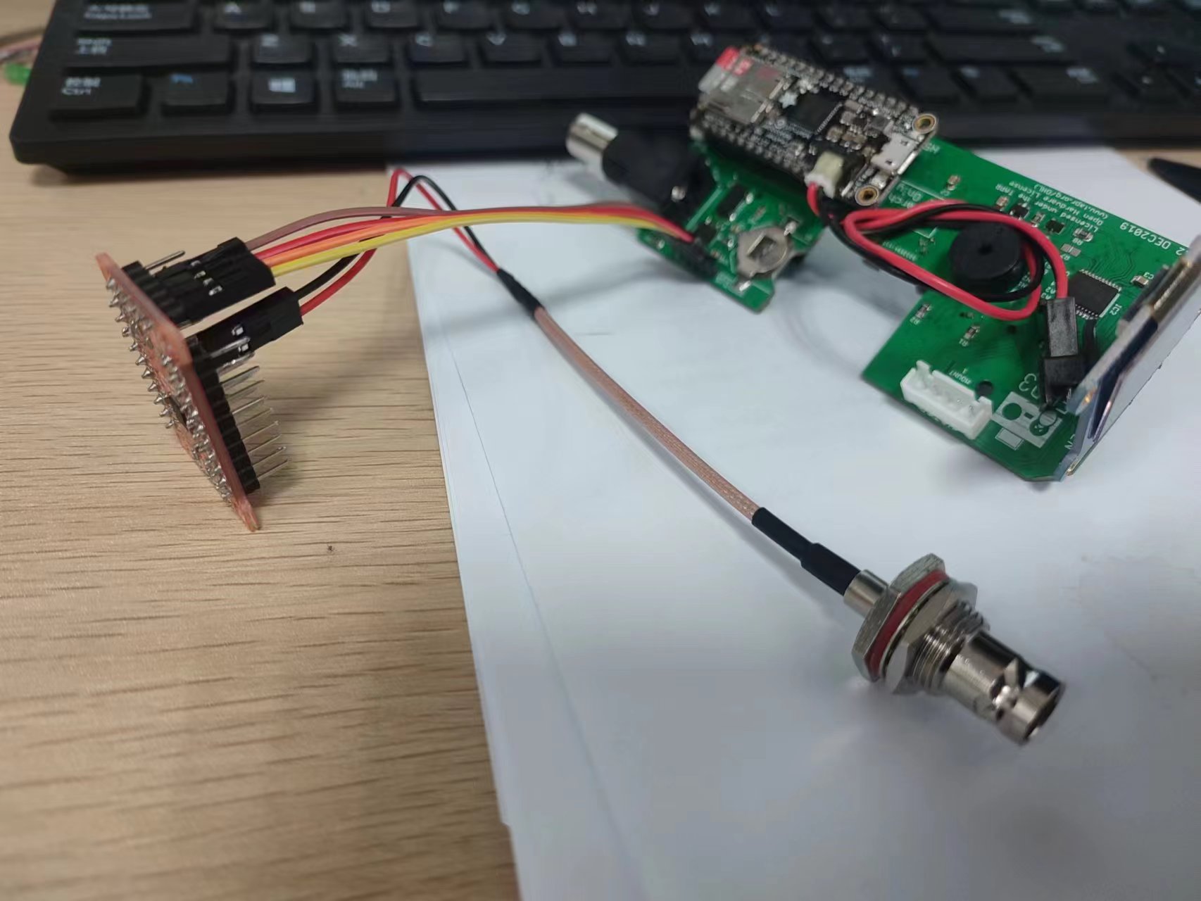
For a while I ended up using the pin 9 method and just not measuring the battery levels. It was not the most formal way but I have a BNC with leads coming out of it, and soldered the signal (red) to the pin and the ground (black) to the Feather GND. THis was more of a retro-fit, but with planning you could use a different type of header and have a spot that's more suitable to this hardware change.
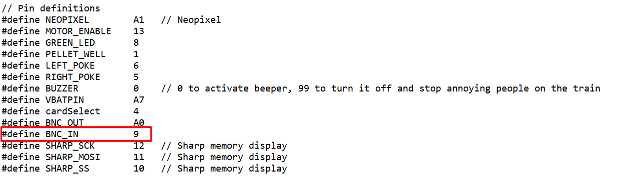
As for the code, for readability I just changed #define VBATPIN A7 to #define BNC_IN 9 in the "a_header.h" script, and in "StarUp" I wrote it as pinMode(BNC_IN, INPUT). You can definitely just use the VBATPIN variable name, but human readability can save you some pain months after you've made any changes to code! Are you thinking of using it as an input as well?
--
You received this message because you are subscribed to the Google Groups "FEDforum" group.
To unsubscribe from this group and stop receiving emails from it, send an email to fedforum+u...@googlegroups.com.
To view this discussion on the web visit https://groups.google.com/d/msgid/fedforum/0d2db813-cfa7-4b21-b139-253fc5a873ban%40googlegroups.com.
Lex Kravitz
Mar 25, 2021, 2:21:27 PM3/25/21
to FEDforum
Hi Vinicius! To use alternative 4 you would need to purchase an I2C GPIO expander and attach it to the headers on the inside of FED3. These are cheap, <$10, here is one example: https://www.sparkfun.com/products/13601
This port expander would be connected with 4 pins: power, ground, SDA, and SCL. The SDA and SCL pins will not operate as GPIOs, but rather will transmit a communication protocol that can mimic LOTS of GPIOs (16 on the above part). So if you wired in that part you can use their library to mimic 16 additional GPIOs. Here is an example from their library on how to read the pins on the GPIO expander. They also have a guide that describes how to use it. So the hardware mod is very simple (4 wires) but you would have to modify the FED3 library to use the GPIO expander.
I have not done this mod, but I don't think it will be too difficult and I'd be happy to work with you on it if you decide to try. How many GPIOs are you looking to add BTW?
Best,
-Lex
Vinícius Borges
Mar 29, 2021, 3:24:32 AM3/29/21
to FEDforum
Thanks a lot Cesar, I will give this a go in the following days. We are currently using the BNC as an input to dispense a pellet in our system, but we would like to get at least one input and one output – so I may then use pin 9 as input and BNC as output.
Vinícius Borges
Mar 29, 2021, 3:32:36 AM3/29/21
to FEDforum
Thanks for the help, Lex. I just purchased a few expander breakouts, I will try to implement this in the following weeks. At the moment, we need one input and one output pin (so for now I will use Cesar's idea of using pin 9), but we will need a lot more in the coming months when we implement miniscopes in our system, so this is a great long-term solution.
Lex Kravitz
Mar 30, 2021, 9:07:05 AM3/30/21
to FEDforum
Sounds good! Yup dropping the battery monitor and using D9 as an input is the simplest hack to get a single input and single output going.
Another idea when you connect it to miniscopes and want to send transmit multiple output events is to send everything on one output line using different patterns of short pulses to represent different events in FED3 (ie: 1 pulse = left poke, 2 pulses = right poke, 3 pulses = pellet). You can decode them later in Python or Excel even. Here is a description of how this works from the Hardaway lab, we also use this approach in my lab and I'd be happy to help you get this going, it requires no hacking just a single line of code in your behavioral program whenever you want to send pulses. Best, -Lex
Vinícius Borges
Apr 1, 2021, 8:39:51 AM4/1/21
to FEDforum
Hello, I just would like to publish that I managed to successfully do the pin 9 modification based on Cesar's comments, and add some context in case anyone wants to do something similar.
In the FED3.CPP, initialize pin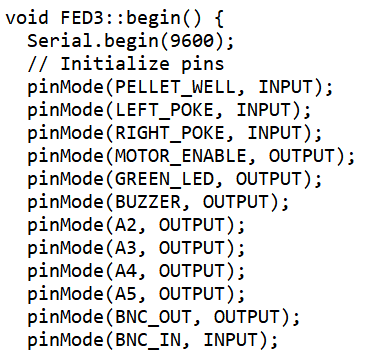
We have a behavioral maze in which we have a beam break (an LED pointed at a photoresistor) which is triggered when the animal approaches the space in which the FED is located (this is connected to an Arduino). We then would like to track when the animal retrieves the pellet (ideally without having to look at the SD card data, but rather acquiring it in real-time).
To change the FED3 to do this, I needed to have the pin 9 as an input and the BNC as an output.
- In the FED3.h file, just add pin 9 as BNC_IN and switch A0 as BNC_OUT
In the FED3.CPP, initialize pin
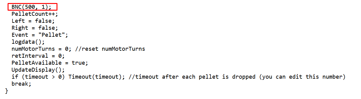
- Then just uncomment this line of code in the dispenser function
Then, in arduino, I just send a pulse to pin 9 once the animal passes by and simultaneously send a pulse to the pi which initializes a timer (food_clk_start = time.process_time() )
When the animal collects the pellet, I send a pulse via BNC to the pi to signal the end of the timer (food_clk_end = time.process_time() - food_clk_start)
Maybe this is too simple, but hopefully it could help someone looking to do the same hack.
Vinicius
Lex Kravitz
Apr 3, 2021, 10:47:33 AM4/3/21
to FEDforum
This is a great solution, thanks for sharing how you did it!!

uest...@gmail.com
Jan 6, 2023, 4:25:17 AM1/6/23
to FEDforum
Just share the testing with the SX1509 board, with those who want to add another BNC port.
Best,
Cequn
Reply all
Reply to author
Forward
0 new messages