
dautan...@gmail.com
Feb 3, 2023, 7:02:42 AM2/3/23
to FEDforum
Hello,

After reading all the comments about TTL output etc...
I end up with a question that "might" solve most of the issue.
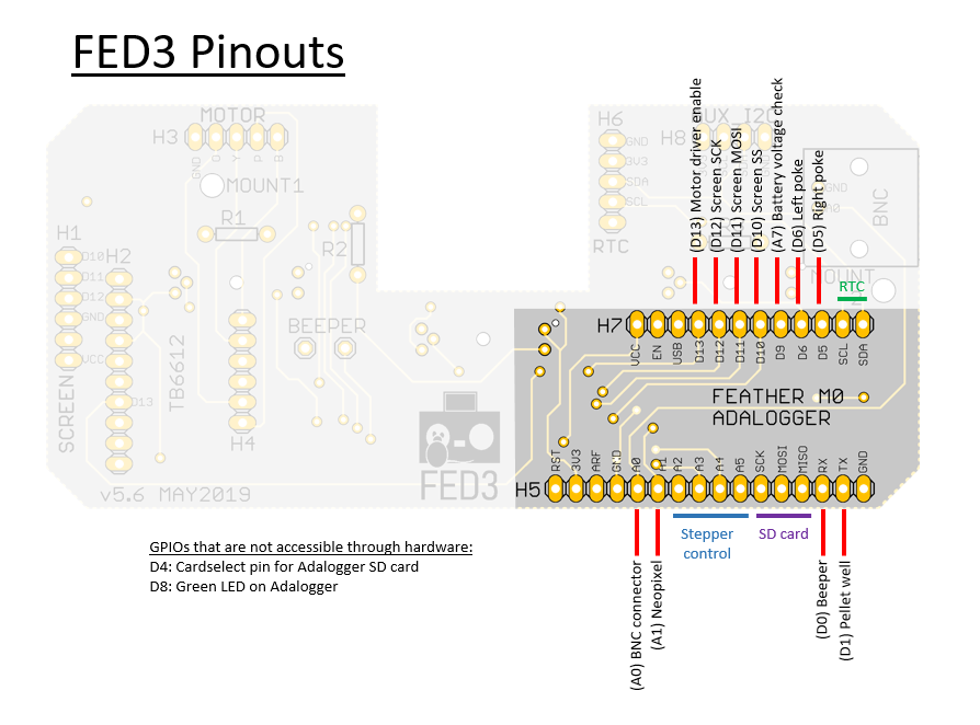
In the FED3.0 the PCB Board is easilly accessible and so soldering a small cable on the left poke/right poke or even pellet pin should be easy right?
However that would means dropping the voltage. While for a TTL it can be increase using another ARDUINO located outside the animal cage that receive "small voltage" and in return send a TTL (3.3/5v) To the photometry (as an example).
I am just wondering if it can affect the way the script count right or left poke?
The soldering would be at this level (see image) an different pins for each output?

Lex Kravitz
Feb 8, 2023, 1:04:45 AM2/8/23
to FEDforum
Hi! Cool idea! I think this will work, the script shouldn't be affected by this mod and it's possible the voltage drop won't matter either. BTW you can also solder onto the relevant pins on the Adalogger, that might be the most accessibly place. Here is the pinout map. Write back if you try it, it's a really interesting idea!
Reply all
Reply to author
Forward
0 new messages