Thermal Radiation & Wind
284 views
Skip to first unread message

Francois
Mar 17, 2022, 3:13:23 AM3/17/22
to FDS and Smokeview Discussions
Hi
I have encountered quite a large discrepancy in results when I ran the same FDS file on two different FDS versions.
I ran the attached file on FDS 6.7.7 and FDS 6.7.5. The resulting flame tilt was significantly more pronounced in the 6.7.7 run (see pictures of the flame). I specified a Monin-Obukhov profile. Note the pictures are taken at the same time step but the same pattern exists at throughout the simulation.
This resulted in a significantly increase in the thermal radiation received by the structure (more than 10 fold difference in the kW/m² received by the roof) as flames are almost impinging on the roof in the 6.7.7 scenario. Note I did not alter the default Path Length but I think the issue here is the significant difference between the flame tilts.
I noticed that in FDS 6.7.6 "Mean forcing for wind has been removed, but the basic input parameters for wind remain the same". I am not sure if this can cause such a significant difference in results (wind tilts)?

Kevin McGrattan
Mar 18, 2022, 11:11:05 AM3/18/22
to fds...@googlegroups.com
Why don't you first compare the wind profiles from the two versions without the fire and all that other stuff in your input file. Just look at the wind first.
Francois
Mar 23, 2022, 6:28:46 AM3/23/22
to FDS and Smokeview Discussions
Thanks for the feedback. I will take a look.

TimoK
Apr 4, 2022, 5:23:13 AM4/4/22
to FDS and Smokeview Discussions
Well, I have about similar case. There is a x=60m, y=20m (periodic boundaries), z=30m case with a 30 MW/m "line" fire that is consisting close to 50 separate tree trunks (HRRPUA boundary condition). Three different cases for the wind (dx=dy=dz=0.25m):
v1: "Open sky"
&VENT PBX= 0.0, SURF_ID='WallOfWind', COLOR='BLUE', OUTLINE=.TRUE. /
&SURF ID='WallOfWind', PROFILE='ATMOSPHERIC',
VEL=-5.0, Z0=5.0, PLE=0.3 /
&VENT PBX=60.0, SURF_ID='OPEN' /
&VENT PBY= 0.0, SURF_ID='PERIODIC FLOW ONLY', COLOR='CYAN', OUTLINE=.TRUE. /
&VENT PBY=20.0, SURF_ID='PERIODIC FLOW ONLY', COLOR='CYAN', OUTLINE=.TRUE. /
&VENT PBZ= 0.0, SURF_ID='GROUND' /
&VENT PBZ=30.0, SURF_ID='OPEN' /
v2: "free slip and vel_grad=0 sky"
&VENT PBX= 0.0, SURF_ID='WallOfWind', COLOR='BLUE', OUTLINE=.TRUE. /
&SURF ID='WallOfWind', PROFILE='ATMOSPHERIC',
VEL=-5.0, Z0=5.0, PLE=0.3 /
&VENT PBX=60.0, SURF_ID='OPEN' /
&VENT PBY= 0.0, SURF_ID='PERIODIC FLOW ONLY', COLOR='CYAN', OUTLINE=.TRUE. /
&VENT PBY=20.0, SURF_ID='PERIODIC FLOW ONLY', COLOR='CYAN', OUTLINE=.TRUE. /
&VENT PBZ= 0.0, SURF_ID='GROUND' /
&VENT PBZ=30.0, SURF_ID='Sky' /
&SURF ID='Sky', COLOR='MAGENTA', VEL_GRAD=0.0, FREE_SLIP=T /
v3: M-O similarity
L=1000000.0 neutral => no T(z) => corresponds to wall of wind inputs
Z_0=0.0002 => sea => corresponds to wall of wind inputs
&WIND SPEED=5.0, Z_REF=5.0, DIRECTION=270.0, L=1000000.0 , Z_0=0.0002 /
Z_0=0.0002 => sea => corresponds to wall of wind inputs
&WIND SPEED=5.0, Z_REF=5.0, DIRECTION=270.0, L=1000000.0 , Z_0=0.0002 /
&VENT PBX= 0.0, SURF_ID='OPEN' /
&VENT PBX=60.0, SURF_ID='OPEN' /
&VENT PBY= 0.0, SURF_ID='PERIODIC FLOW ONLY', COLOR='CYAN', OUTLINE=.TRUE. /
&VENT PBY=20.0, SURF_ID='PERIODIC FLOW ONLY', COLOR='CYAN', OUTLINE=.TRUE. /
&VENT PBZ= 0.0, SURF_ID='GROUND' /
&VENT PBZ=30.0, SURF_ID='OPEN' /
&VENT PBX=60.0, SURF_ID='OPEN' /
&VENT PBY= 0.0, SURF_ID='PERIODIC FLOW ONLY', COLOR='CYAN', OUTLINE=.TRUE. /
&VENT PBY=20.0, SURF_ID='PERIODIC FLOW ONLY', COLOR='CYAN', OUTLINE=.TRUE. /
&VENT PBZ= 0.0, SURF_ID='GROUND' /
&VENT PBZ=30.0, SURF_ID='OPEN' /
All cases are run just with the wind and wind+fire (file names correspondinly v1, v1fire, v2, v2fire, v3, v3fire).
&RADI RADIATION=.FALSE. / no fire test case
&PRES VELOCITY_TOLERANCE=0.001, MAX_PRESSURE_ITERATIONS=100 /
I have done also v3 with radiation, but same results. And the PRES I have, because some of cases had numerical instability without it, but the cases look same with and without PRES (as long as the without PRES did run).
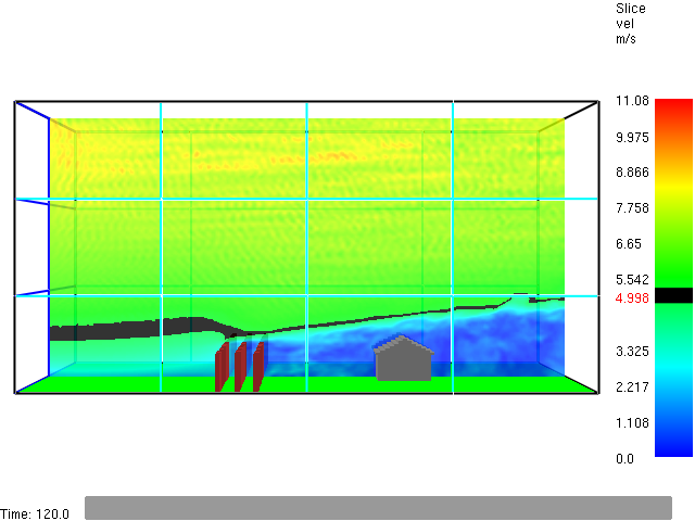
The figure below are in the order:
v1
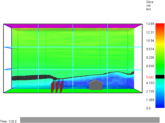
v2
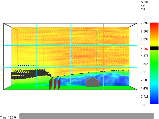
v3
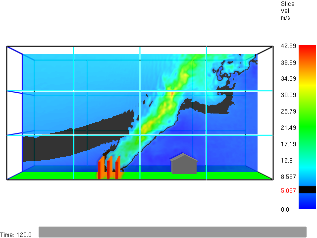
v1fire
v2fire
v3fire
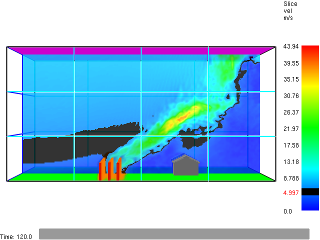
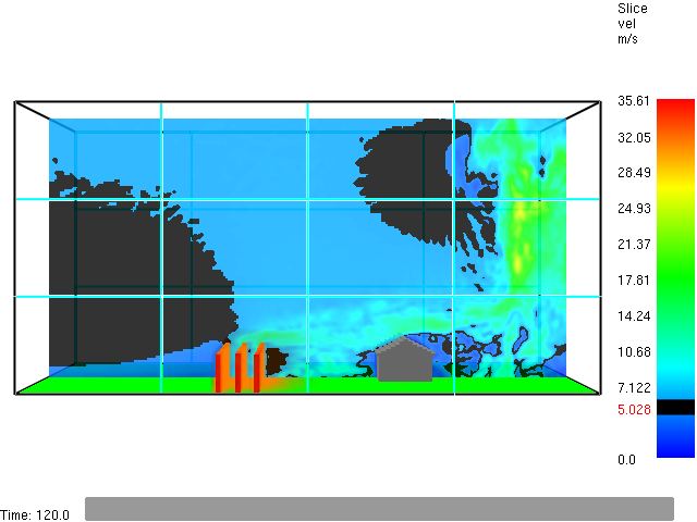
Show are: HRRPUV (Smokeview orange color, does not show up very well in the figures) and velocity (magnitude) SLCF and black is 5.0 m/s there, which is the wind speed in the inputs at the elevation of 5m.
I did also the cases with 15 m/s first, but with similar results ==> something seemed to be wrong ==> reduced the wind speed to 5 m/s. And I have run the 5 m/s cases v1fire and v2fire using both 90m and 150m z_max. I have not checked them yet, they are downloading slowly from the Linux cluster to my laptop (I'm remote working still due to covid situation). But I would say that the v1 and v2 cases do not change much due to the z_max. But I'm just checking there how much sky I should add to the "wall of wind" model that I will be using in actual cases. This is just a test case that was done some 15 years ago by someone else than me. I.e, I was trying to check if I'm able to get the old results. Not to check how FDS has changed during the years, the aim was more or less to validaty myself (Am I able to do this kind of simulations?).
Something that I can see form the figures below: The v1 case (wall of wind with open sky) is not too good with z_max=30m. The fire plume (whole y range line source) is pushing the incoming air upwards to escape from the OPEN boundary. The v2 case performs better with the free slip and vel_grad at the sky. I would expect, that the v1 and v2 cases would be closer to each other, when I see the z_max = 90 and 150 m cases.
The v3 (M-O) case does something that is wrong. It pushes the flames along the ground (horizontally) towards the building. This is clearly seen in the temperature slice (not attached) and also the HRRPUA (orange color in Smokeview). The HRRPUA is "in the three trunk" region and next to it on the right side, it does not rise upwards at all. In the v1 and v2 cases HRRPUA is along the fire plume, the velocity slice shows it similarly as the temperature slice (not atttached here).
Wbr,
Timo
TimoK
Apr 7, 2022, 5:29:02 AM4/7/22
to FDS and Smokeview Discussions
Well, I add here the 30 s time averaged (using Smokeview dialog) gas temperature and velocity (=speed, i.e., not a vector) figures for the three cases with fire.
Below the gas temperatures for v1, v2, and v3 (OPEN sky, VEL_GRAD sky, M-O similarity WIND), respectively:
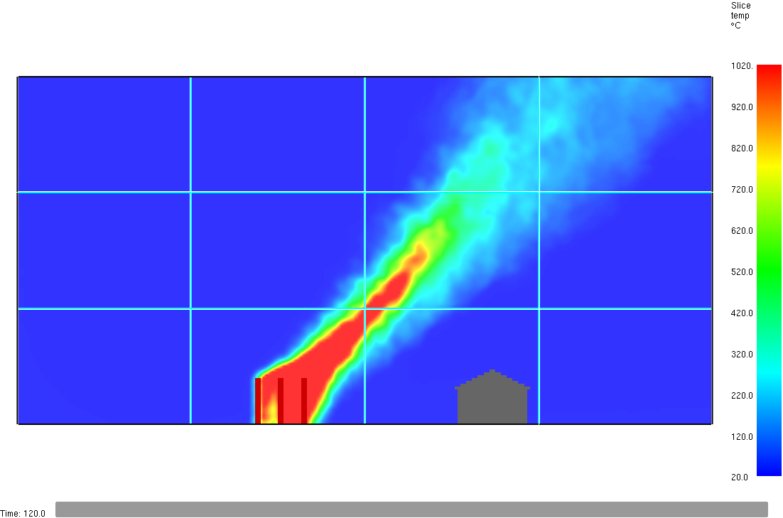
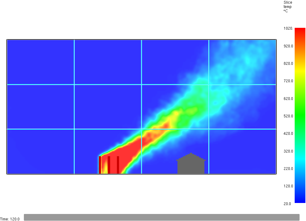
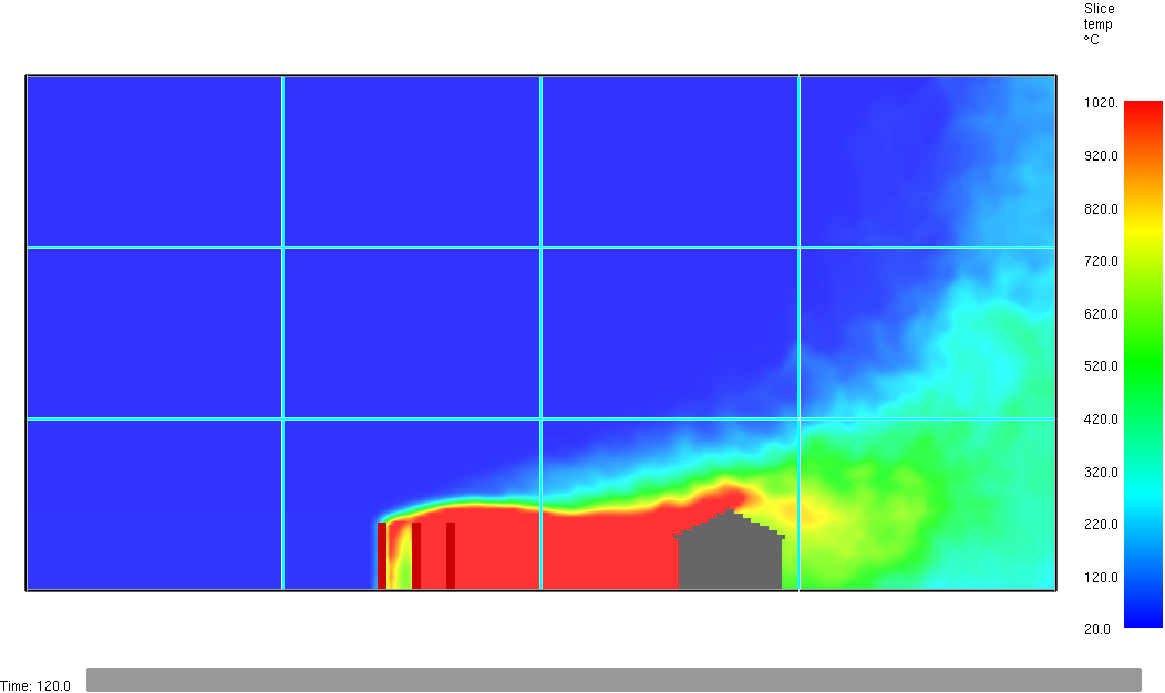
The v2 (the middle one above) is the best one. It is closer to the z=90m and z=150m cases that I have already tested. The v1 (OPEN sky) makes the fire plume to rise too much in this z_max=30m case. For z_max=90 and 150m the plume does not rise so much. The v3 (M-O) is putting the flame along the ground all the way up to the building. This can not be true.
Same is, of course, seen in the velocity plots below:
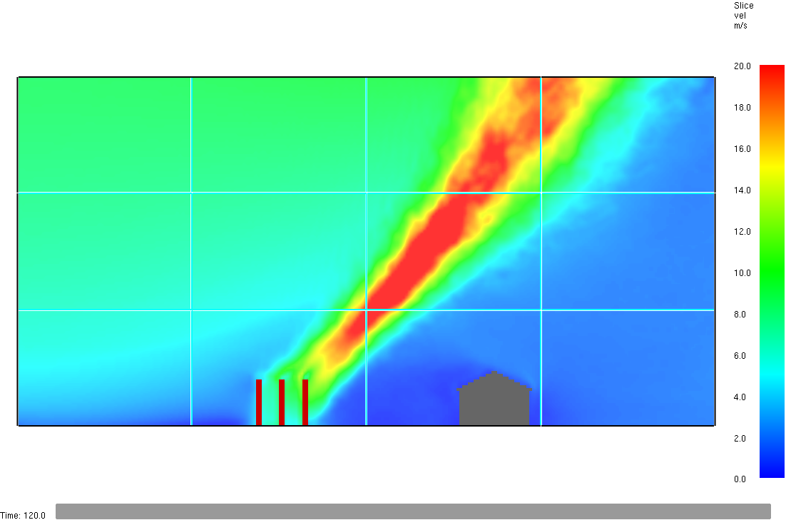
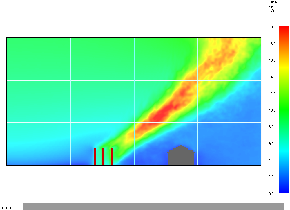
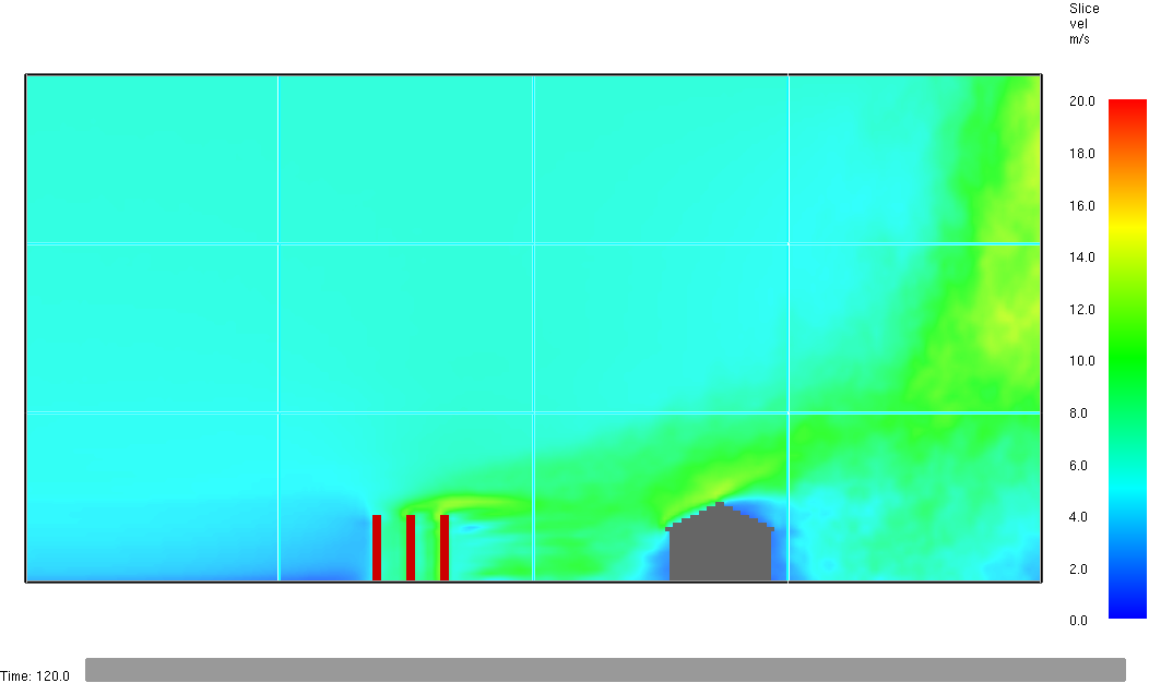
In the last one (M-O) there seems to be something odd also at the +x boundary (the down wind side). The +x boundaries in v1 and v2 seem to work better. In all cases, the +x boundary is OPEN. I'm right now analysing results for the cases, where x-domain is exteded 20 m and 40 m further in the down wind side (not done for the M-O case, because the fire plume is already bad here and no need to check it further). I do the 20m/40m extension for my own purposes, i.e., to see what size of domain I should use for these kind of simulations later, when I'm doing the actual simulations that I plan to do later this year. (= I'm learning how to do wind simulations right now.)
Wbr,
Timo
TimoK
Apr 7, 2022, 6:19:57 AM4/7/22
to FDS and Smokeview Discussions
Well, it might be that my test geometry is not the best one. It might be that it makes odd results. When I increase the x-domain size, the results of the v1 and v2 cases also get bad, in the long ones (40 longer than above figures), the flame is going towards the building like in the short M-O case. This might be due to the geometry. I should increase the width of the domain. Now the periodic boundaries are quite close. The geometry is like a narrow pipe. I'll expand the geometry to the sides and take the periodic boundaries to OPEN boundaries. Then the flow would not be in a narrow pipe and I would expect the fire plume not to be at the ground. And I'll make the fire source to be a finite width (about 20 m wide as it is in the input file, domain is wider). There might be some artefacts rising from the more or less 2-dim geometry set up. I'll make a more 3-dim test case, i.e., not a "infinite line fire".
TimoK
TimoK
May 13, 2022, 7:00:40 AM5/13/22
to FDS and Smokeview Discussions
Well, this discussion "could be closed". The MO and Wall of Wind seem to give similar results, when the domain size is large enough. The wall of wind case is more sensitive to the too small domain than the MO case. But, interestingly, the some 15 or 20 years old FDS Wall of WInd with small domain gave quite different results than the present (well, quite present, i.e., 6.7.7) version. So, something has been changed during the years.
TimoK
Reply all
Reply to author
Forward
0 new messages