Repeated object MULT shape vs. Voxels in Blender FDS
216 views
Skip to first unread message

John S.
Oct 31, 2021, 10:05:43 AM10/31/21
to FDS and Smokeview Discussions
I changed my OBST cylinder in my FDS case from a repeated object MULT generated cylinder (as in FDS guide) to one drawn with voxels in Blender FDS, and the temperature of the thermocouple on average changed by 14C. The device was not obstructed on either case as far as I could tell.
Does anyone have an opinion as to which type of cylinder/OBST physics would more accurately model the flame? Specifically with HT3D on all OBST?
The model is a very small system trying to simulate a candle flame.
Thanks for any help!

Marcos Vanella
Nov 1, 2021, 8:56:59 AM11/1/21
to fds...@googlegroups.com
Have you conducted a grid refinement study? For that you want to reduce the FDS mesh size and also the voxel size for your geometry.
--
You received this message because you are subscribed to the Google Groups "FDS and Smokeview Discussions" group.
To unsubscribe from this group and stop receiving emails from it, send an email to fds-smv+u...@googlegroups.com.
To view this discussion on the web visit https://groups.google.com/d/msgid/fds-smv/70e51322-0bb3-4c73-b0b8-b1c47b94fb5bn%40googlegroups.com.
John S.
Nov 1, 2021, 3:58:13 PM11/1/21
to FDS and Smokeview Discussions
I haven't. What is the procedure? Just as it sounds, reduce grid size and see if the results change and by how much? I know how to change the voxels, too. My current code has a relatively large mesh size of .0075 m for a small system of .15 m IJK. I wanted to eventually reduce it to .005 or .0025 but I have not tried yet. If you think it will be useful, I will try it. There is a paper on candle flames where they reduced the mesh to 2mm by 2mm by 1mm around the flame and wick obstruction.
My concern is that I think the repeated object MULT cylinder I have in my OBST is causing inaccurate data. A 14C difference between two objects that take up the same space and should be made of the same number of OBST blocks doesn't seem right. It also throws a warning when I go to divide up the mesh, even with the entire OBST in its own mesh. I figured that Blender FDS is used to model very large systems with complex geometry like houses for fire detection, so it is probably the better bet for my simulation. I am unsure how the candle OBST was drawn in the NIST paper on candles.
Unless the cylinder drawn in Blender is hollow, but I'm pretty sure it's made "solid" of voxels.
Thanks for your response.
Marcos Vanella
Nov 1, 2021, 4:21:48 PM11/1/21
to fds...@googlegroups.com
Yes, you want to refine the mesh and the voxelization until differences are "small" enough for you to state the simulation results are not dependent on the discretization.
Look at your temperature differences as a percentage of the temperature increase you see. How much are these 14 C of the max temperature increases (Tmax-Tambient) registered by the thermocouples? 1%? 50%?
About what the cylinder looks like as seen by FDS, in Smokeview hit the Q key to see how different the mult and blender cylinders are. If they look exactly the same, then you have some parameter other than the geometry different.
To view this discussion on the web visit https://groups.google.com/d/msgid/fds-smv/d2f32c4d-de0a-44cd-b463-686b93d41718n%40googlegroups.com.
Marcos Vanella
Nov 1, 2021, 4:26:44 PM11/1/21
to fds...@googlegroups.com
BTW there is a description on grid resolution and convergence on the FDS User guide. Search for Mesh resolution and the references there.
John S.
Nov 1, 2021, 5:16:28 PM11/1/21
to FDS and Smokeview Discussions
I will try this and let you know. The only issue I have is that the "glass container" for the candle and the "Candle wick" are 1 mesh size thick, so they will have to be adjusted when I refine the mesh and that will inherently cause differences.
I tried pressing Q key. Block location as input gave SMV output "glass container" as only 1 voxel thick, approximate but not exact to my hand drawn container with OBST rectangles. The candle bulk cylinder was exactly the same. However, the snapped to grid block location showed the solidified hollow cylinder drawn in Blender as 1 voxel thick as being three voxels thick in all locations. Which of these is used for the calculation? I would think however that a three times thicker "glass" cylinder surrounding the "wax" cylinder would not account for such a large fluctuation at the thermocouple.
To be clear, the 14C difference is from the average of all temp measurements at a thermocouple for the last 10 minutes of an 1 hour and 10 minute simulation. I will check the Tmax and Tambient for the entire calculation as well.
Thanks for your help.
John S.
Nov 1, 2021, 5:16:43 PM11/1/21
to FDS and Smokeview Discussions
I will also consult the FDS Guide.
Marcos Vanella
Nov 2, 2021, 8:30:42 AM11/2/21
to fds...@googlegroups.com
By default SMV will show the objects as you defined them in the input file. When you press Q you get the snapped to grid obstacles, which is what FDS uses in the calculation.
To view this discussion on the web visit https://groups.google.com/d/msgid/fds-smv/91d5416a-aa26-408c-9b6f-02ef85af981an%40googlegroups.com.
John S.
Nov 2, 2021, 9:01:14 AM11/2/21
to FDS and Smokeview Discussions
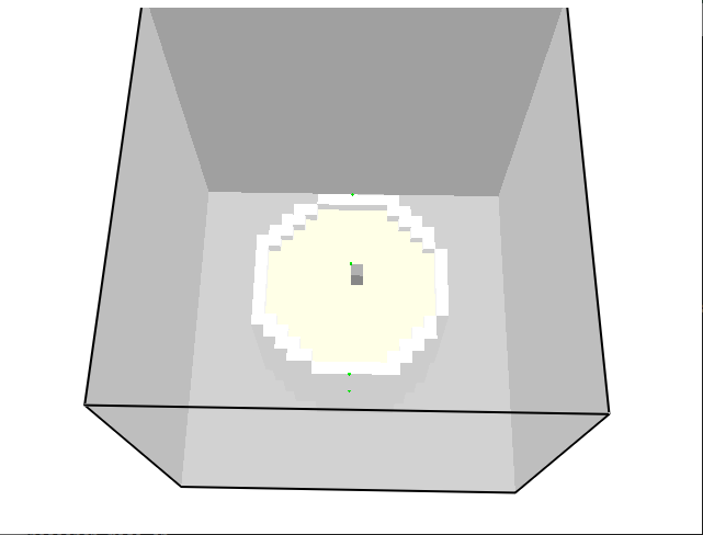
Cylinder with MULT repeated objects:
Cylinder with Blender user defined:

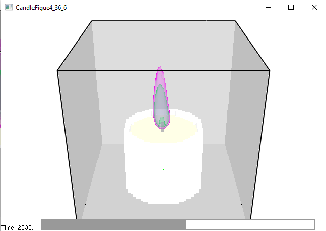
Cylinder with Blender FDS calculation:
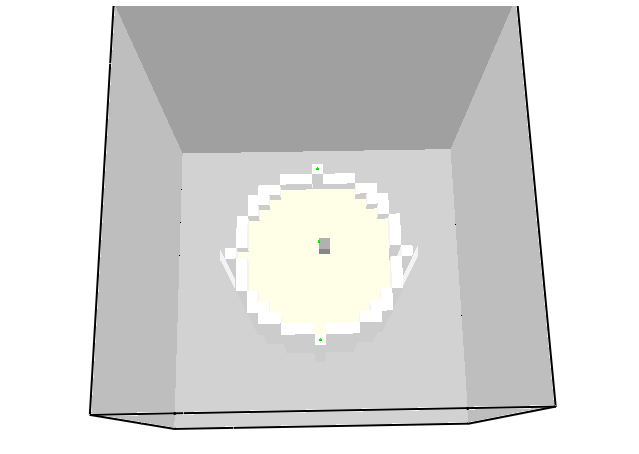
The little green dots are the thermocouples. The reading is from the bottom one on the edge of the white "container" cylinder on each. The first case had a average temperature from 60-70min simulation time of 62.6C. The bottom with Blender cylinder case had the same thermocouple with an average temp from 60-70min of 77.8C.
Marcos Vanella
Nov 2, 2021, 9:14:25 AM11/2/21
to fds...@googlegroups.com
Do you have a flame in the middle? How many cells across the flame do you have? The two geometries are different and the discretization is coarse by the looks of it. I'd say you have to do a grid refinement study.
To view this discussion on the web visit https://groups.google.com/d/msgid/fds-smv/69dc707e-5441-4eae-9a44-c9e4c740fa5dn%40googlegroups.com.
John S.
Nov 2, 2021, 9:32:22 AM11/2/21
to FDS and Smokeview Discussions
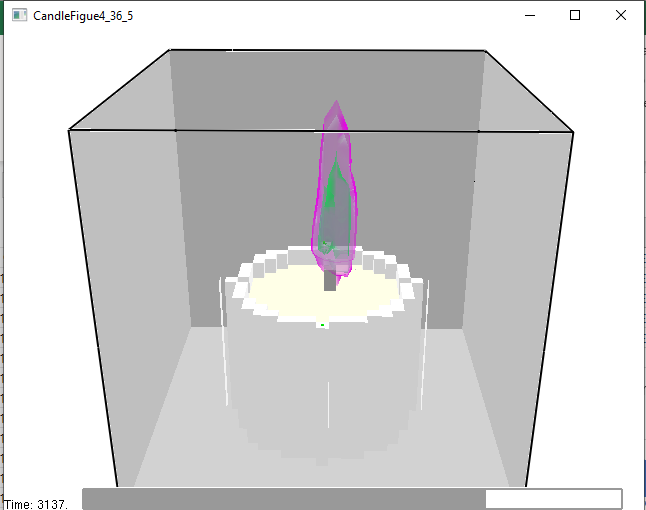
Flame is like this: Vent by mass flux out of the "wick" obstruction top half.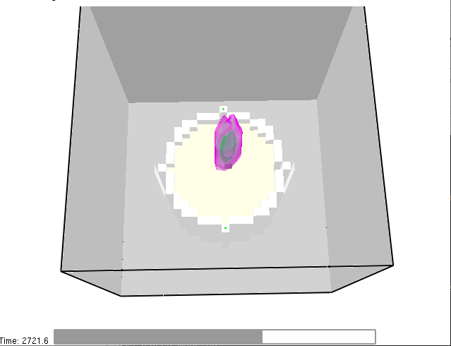
I have been advised that my grid may be too coarse, but I was trying to work out all the kinks in my code before I refined.
I will refine and do the study to see what happens.
Thanks for your help.
John S.
Nov 2, 2021, 9:34:07 AM11/2/21
to FDS and Smokeview Discussions
I just didn't expect to have such a large difference at that thermocouple with the small differences between the codes. Seems like there is another issue.
The Blender code is easier to write, so that may end up winning and I know Blender is used more often by other users so it seems like the safer bet.
Thanks.
John S.
Nov 24, 2021, 10:04:11 AM11/24/21
to FDS and Smokeview Discussions
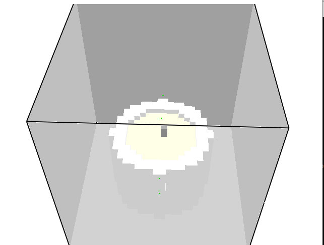
I ran a very long simulation with .0025 mesh across the plume and "candle" OBST. It seems that the thermocouple at the same point, all other things being the same as voxelization in Blender FDS, gave an average temperature over the last 10 minutes of a 1hr10min simulation of 58.2C for .0025 refined mesh versus the .005 mesh at 77.8C.
Differences were that the voxelization for the .005 mesh had the thermocouple in the middle of a "glass container" voxel and not on the edge (see photos below). Question: Is the temperature isosurface picking up area that is not really flame/plume, i.e. I know there is some area outside the flame that is at near flame temperature, for instance in a candle flame at 1100C?
Overall, I would be wary to jump to .0025 mesh even though it looks better in Smokeview. First of all, I don't have access to a powerful enough computer to do the simulations efficiently. Second of all, I am trying to recreate a real world burn test, and the temp I am shooting for for this simulation is around 63.3C. The flame in the .0025 mesh is unrealistically big for the real world candle. If I use voxelization at .005 mesh and reduce the flow rate from the vent then the flame will be much better height wise.
Thoughts?

Kevin McGrattan
Nov 24, 2021, 10:45:21 AM11/24/21
to fds...@googlegroups.com
'THERMOCOUPLE' is a gas phase quantity and must be in a cell that is not solid. Do not put it on the border or inside a solid. If you do, its result is meaningless.
John S.
Nov 24, 2021, 10:57:08 AM11/24/21
to FDS and Smokeview Discussions
Thanks, I did not know that. Well, I guess I don't have much from this result besides the Smokeview simulation.
Is there any way to measure the temperature on the surface of a solid?
Message has been deleted
John S.
Nov 24, 2021, 11:08:48 AM11/24/21
to FDS and Smokeview Discussions
Can I use WALL TEMPERATURE to obtain a "rim" temperature at a certain cell on an OBST?
Ex:
&DEVC XYZ=0.0,0.0,0.0, IOR=3, QUANTITY='WALL TEMPERATURE', ID='temp' /
John S.
Nov 24, 2021, 11:50:42 AM11/24/21
to FDS and Smokeview Discussions
Seems to work when placing the WALL TEMPERATURE in the Y direction on the side of the OBST surface.
Question:
Is it possible to place a WALL TEMPERATURE at the 1 mesh thick face of the "container" OBST? It was unable to when I tried putting the IOR=3 for the z direction. Got the following error:
ERROR: Reposition DEVC No.1, ID = Outer Rim
FDS cannot determine which boundary cell to assign.
Marcos Vanella
Nov 24, 2021, 12:06:27 PM11/24/21
to fds...@googlegroups.com
Hi John, read the latest User Guide section 21.2.1 Devices on solid surfaces. You want to place the device in a cell right off the wall (in the gas) and use IOR to
define the direction the wall points to. Check also the first WALL TEMPERATURE devc in Examples/Heat_Transfer/back_wall_test.fds to get an idea. The device is related to the first OBST in the list.
A good way to test you have picked up the right wall temperature is make the SURF_ID of your rim have TMP_F=50 for example, and check that after a while you get the 50 deg C.
--
You received this message because you are subscribed to the Google Groups "FDS and Smokeview Discussions" group.
To unsubscribe from this group and stop receiving emails from it, send an email to fds-smv+u...@googlegroups.com.
To view this discussion on the web visit https://groups.google.com/d/msgid/fds-smv/0a78892c-4167-4b43-8820-48b9d5fa2b5en%40googlegroups.com.
John S.
Nov 24, 2021, 12:17:16 PM11/24/21
to FDS and Smokeview Discussions
I think I got it to work using the Devices on Solid Surfaces in 21.2.1 section. I have a wall that faces positive y direction and a WALL TEMPERATURE device with IOR=2. I get no error when I place it in the top cell of the wall with the y coordinate at the height 1 mesh below the top of the wall. I checked quickly the SMV file and there is a green device directly in the center of that cell.
It throws an error when I try to put the WALL TEMPERATURE on the top face edge of that OBST. I think it can't decide where to put it because the edge is only 1 mesh thick. I think the device on the wall facing positive y will be OK for my simulation.
Thanks for all the help.
John S.
Nov 24, 2021, 1:05:09 PM11/24/21
to FDS and Smokeview Discussions
I would add that the hrrpuv at xyz(0,0,.0825) over the last 10 minutes of the 1hr10min simulation was 10543 kW/m for .0025 refined mesh versus 16115 kW/m3 for the .005 mesh.
So there is obviously something going on there.
Reply all
Reply to author
Forward
0 new messages