
Steven Yaeger

I I kept the SSR assembly intact, I just moved it from the front hole to the back hole on the other side.
For the power supply, I used a small piece of extruded aluminum. I mounted the aluminum to the holes that hold the leg on. And mounted the power supply to the aluminum using the existing holes in the power supply shield. I mounted the power supply as close the back wall as possible. It comes a little close to the pins on the switch, but some soldering and heat shrink tubing will eliminate any possible problems.

I used a couple of washers under the extruded aluminum, to give the back cover some room to slide into its normal position. Between the extruded aluminum and the front case.
I also powder coated my case "Harbor Freight Yellow", yeah I know, looks a lot more orange than yellow... And I powder coated the legs black (in order to powder coat the legs, I had to remove the mill coating by soaking them for about 15 minutes, in a bath of diluted muratic acid).

Herb Winters
the washers under the angle aluminum to give the case space to slip umder a Perfect solution.
I had problems with that on my power supply installation.
I will offer this option to the people who are having me build there Kit Too.
Thanks for the post and pics
Herb Winters
I think I see a couple problem with these changes. the wires come up from the optical spool control are not long enough to reach the left side.
Might be able to route the cable out the left side of the Plastic optic holder but you would need to change the plastic part.
Steven Yaeger
Herb Winters

james s
Herb Winters
@Steven, @James s
@Steven I liked this Idea of placing the SSR, PCB and Terminal Strip on the Left side and then mounting the Power supply Vertical. However the Standard Bracket was broken. Even after gluing it it did not have enough strength and the PCB Blocks access to the SSR terminals. So
Here is a mount that hold everything on the left side securely without Blocking any of the connections.
The Bracket below is for the Left side I will also make a Right Side version for those people who would prefer it. I will put the STL files up on thingivers and post links here soon !
@Steven I added a notch on the outside for the back panel to slip under also the PCB is in the same place on the Left side so your cable should reach now. (you will need to make the cable come out of the left side of the Optic Assembly.)
Though you might appreciate these features :)
would really like any feed back on anything else that I should add to this thing.

Herb Winters
its a little weird but works fine.
james s
Herb Winters

https://www.youmagine.com/designs/herb-winters

David Randolph
Steven Yaeger
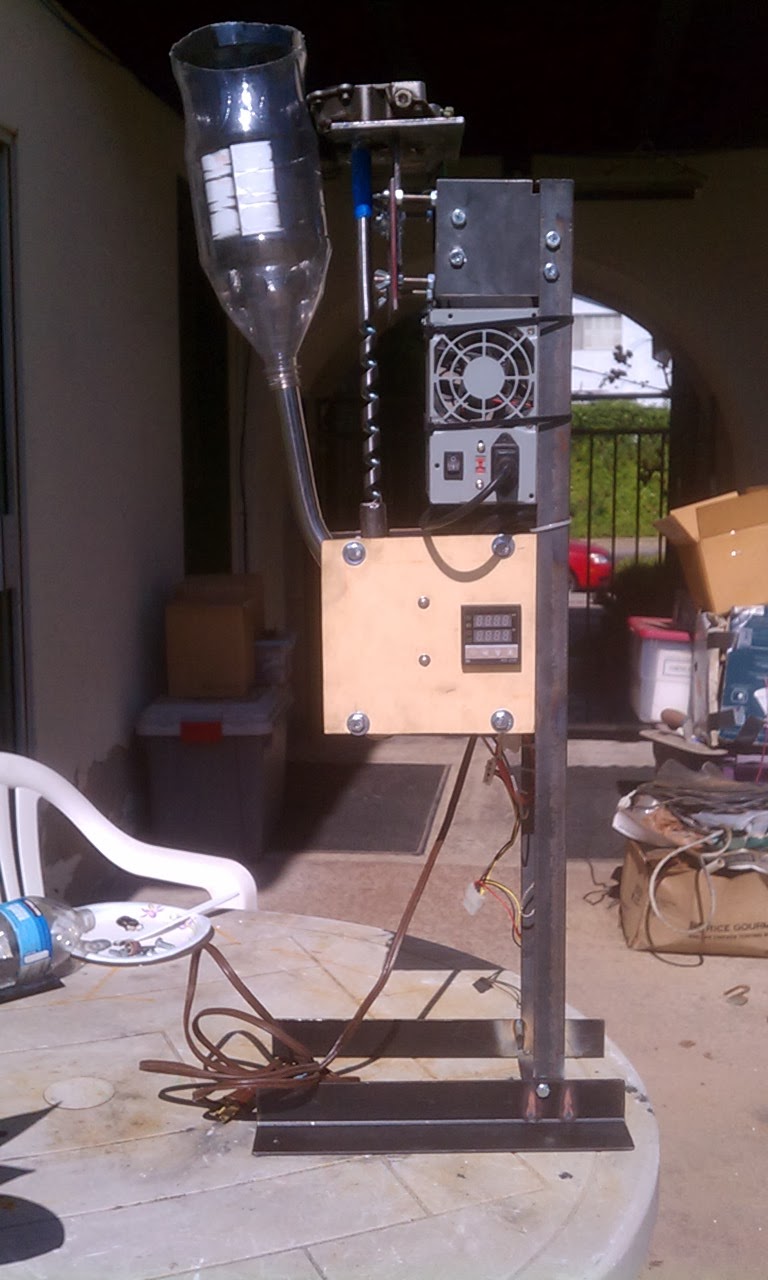
Here pictures of my finished ExtrusionBot (prior to putting in the thermal insulator cloth).

I switched the legs, so that the cables could reach the controller board (now mounted on the left side).
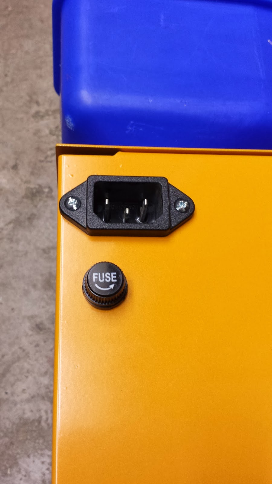
On the back cover, I replaced the supplied power cable with the power socket from an old PC Power Supply.
I replaced the drive motor's rubber chain tensioner with an adjustable aluminum bracket.
The Spooler Motor Switch wires come off sideways instead of straight up, so they don't interfere with the power supply.
Since the hotbed on my 3D Printer is quite up to printing with ABS yet, and I currently only have ABS filament, instead of printing a bracket to hold my electronics, I fashioned one out of 2 small pieces of extruded aluminum. To give enough clearance for the screw to hold the cover on, I used a couple of 1/4 inch or so thick blocks of aluminum as standoffs.
I replaced any of the wires that came with the kit, that might require more than digital signal current, with thicker wires.
I moved the fan... The spool I have is 3 3/4 inches in radius. And that was too big to fit with the fan in the stock position. So I put the fan on the leg with the motor. This allows me to take the back cover on and off without messing with the fan.
Because my kit was missing the filament pulley and the black spooler motor spindle extension, I had to make my own versions of them.
I put a heat sink on the drive shaft motor, with mounts for a small fan (but the small fan it had was bad, so I need to replace it). I suspect if I have the chain tensioned correctly and I wait until the unit has been at the set temperature for 5 to 10 minutes before turning on the main motor, I probably won't have over-heating problems.
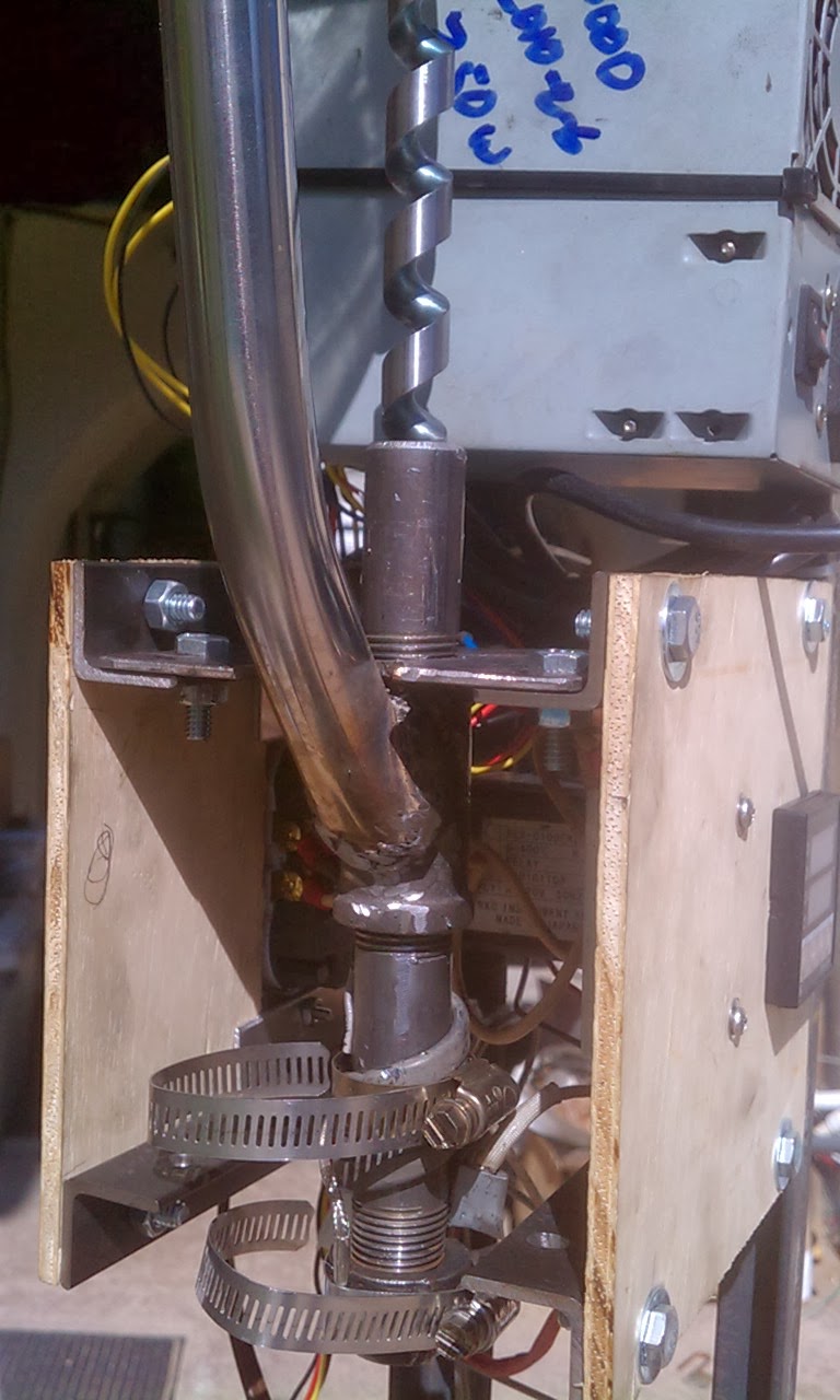
And just because I was in a modding mood, I leveled out the extrusion tube. I put a second fender washer on the lower mount. And on the upper mount, I trimmed down the bolt and nut and put the lock washer inside the bracket instead of between the bracket and the fender washer. These 2 little changes made the extrusion tube almost completely parallel to the front face.


This is a picture of the drive motor's heat sink.

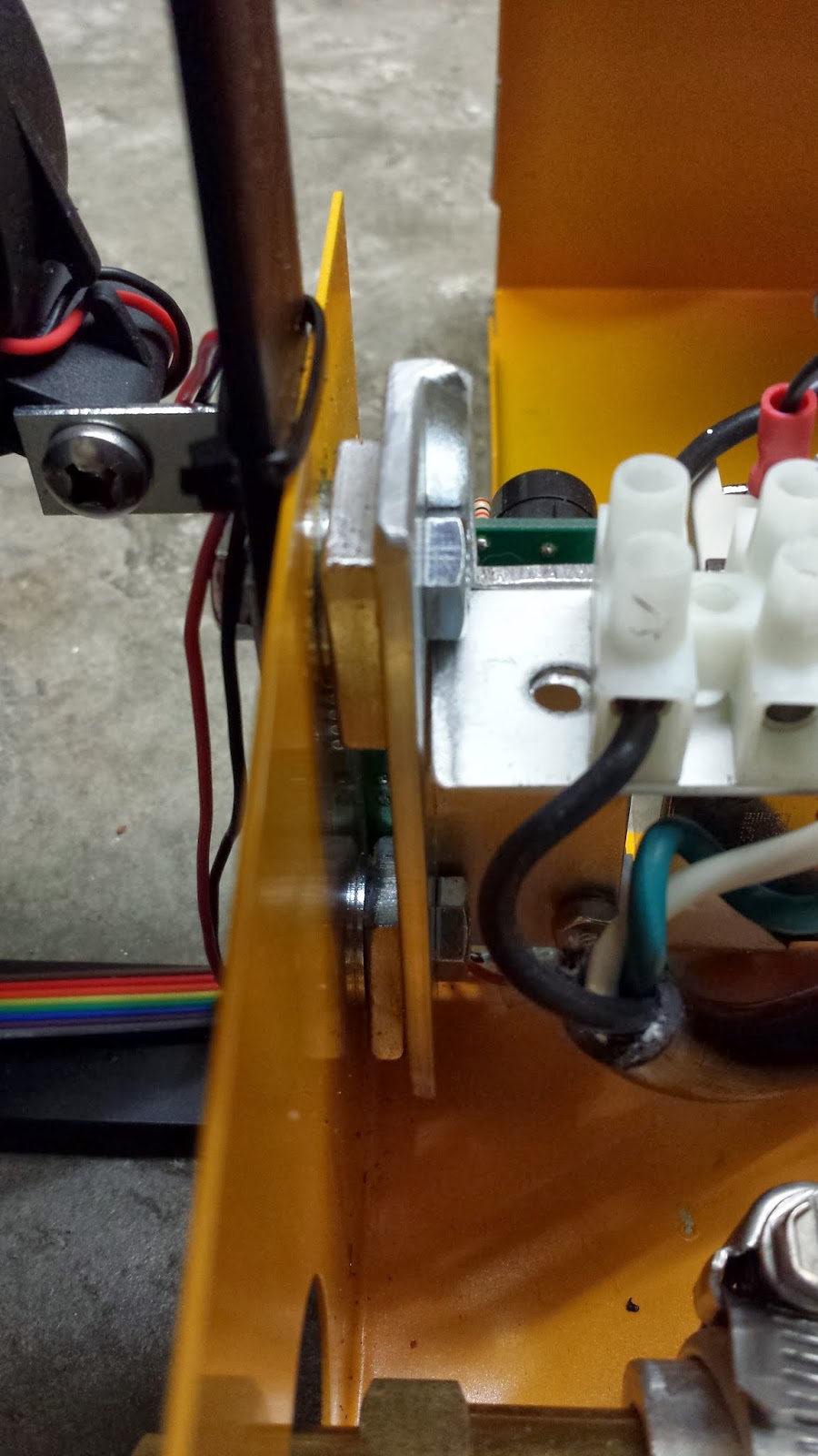
This is a picture of the aluminum chain tensioner, that replaced the rubber piece.

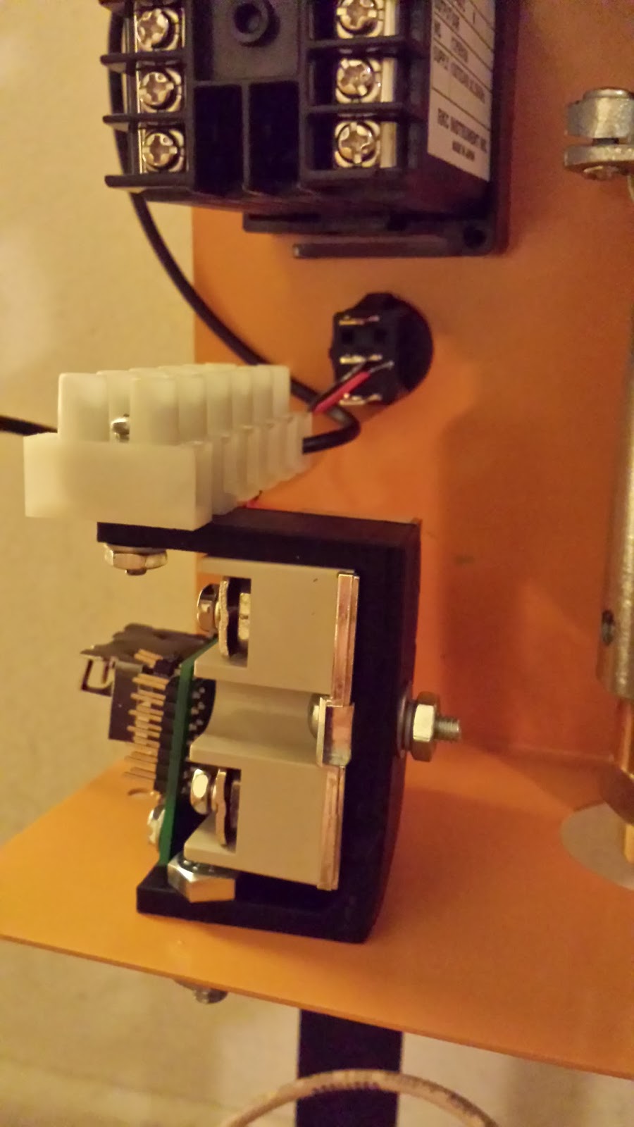
These are pictures of the electronics bracket.


The PC Power Socket.
The new fan position.


Clearance around the hot extrusion tube, that will be wrapped in the insulation blanket.

Fabricated spooler motor mount and spooler motor switch assembly.
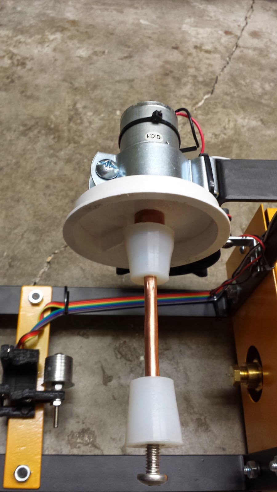

Centered Extrusion Nozzle (made it easier to get the insulating blanket around the extrusion tube).

Herb Winters
@Steven Yaeger, Very nice work ! I am making a aluminum Heatsink for the main motor now. I looked for a hobby motor heat sink that would work but could not find one. Did you find and of the shelf heat sink that you used?
I also think that the aluminum chain tensioner is excellent as it looks like it would also help stablize the motor up and down as well as sid to side. would like to have more information on what type of stock you made it with.
was it U channel stock aluminum?
I was thinking about adding a washer to the extruder mounts to put it in the center like you have done but I think the reason it was off center was to aim it straight at the take-up roller so that the hot plastic is not bent coming out of the extruder. I guess the real answer will be if it makes good plastic filiment then it is much nicer.
on Note I did not see here is if you flip the take-up reel motor to the other side you need to reverse the polarity on the motor because it will need to turn in the opposite direction.
Very Nice work But it now makes me have lots of Questions:)
have you extruded any plastic filament?
does the aluminum heat sink work to keep the motor cool?
Is the filament holding to the +/-0.1mm tolerances?
does the Reel load up neatly? (this is my goal I cannot stand the Rats nest that most of the home grown extruders make )
I only had my Extruder running for about two day I had messed up drilling the rubber stoppers so bad that the spool would walk off the spooler.
however during that time I was able to extrude about 6feet onto a spool and after I tool it off and found that it was very good I measured it from 3.08mm to 2.98mm I was happy other than I needed the sppol to stay on more than 90 seconds.
so I have taken it apart and am doing upgrades to get it right so please let me know what works or what doesn't I will do the same as soon as I get it done I will post all the details.
Steven Yaeger
> was it U channel stock aluminum?
There were 2 reasons I went with the adjustable aluminum gear box tensioner setup. One was because of the other tensioner modifications posted here. And the other was so I could adjust the tension on the chain. I want it taught, but I don't want it so taught that it is creating unnecessary friction in the gear box.
> on Note I did not see here is if you flip the take-up reel motor to the other side you need to reverse the polarity on the motor because it will need to turn in the opposite direction.
> have you extruded any plastic filament?
> does the aluminum heat sink work to keep the motor cool?
The main reason I backed the ExtrusionBot was because of the motor. Previously, I've built a couple of filament extruders. The first one was a sideways one, based on the Lyman design. It taught me pretty quick that there was just too much friction generated by trying to push the plastic horizontally through the system. So the second one I did was a vertical extruder, like the ExtrusionBot. And, like the ExtrusionBot, it was also consistently generating about 4 feet of decent quality filament per minute. But unlike the ExtrusionBot, it was burning through motors. I was using the motors and gear boxes from power windows. But the pressure from the arbor, pushing back out of the tube against the gear boxes of the power window motors was eventually burning them out.
The one thing designing and building my own filament extruders taught me was that motor friction (leading to motor burn out) is one of the 2 biggest problems to overcome in the design (the second problem, at least for vertical extruders, is being able to feed the pellets, without the feeder tube getting jammed).
The power window motors were burning out because of the friction generated in their gear boxes, by the back pressure from the arbor. It looks like Mark's use of the top end cap (with a hole for the narrow section of the arbor), is probably a solution that would have worked for stopping my power window motors from burning out. The end cap absorbs the back pressure from the arbor, so it doesn't get pushed out of the extrusion tube.
> Is the filament holding to the +/-0.1mm tolerances?
Something else doing my own filament extruders taught me is that the resulting filament size is dependent on 3 things. The first one is a one time fix but the second two are somewhat environmental.
1. Getting the initial nozzle hole size correct (the correct size is NOT the size you want the ending filament to be, the filament expands a LOT as soon as it leaves the nozzle).
2. After the filament leaves the nozzle, cool it as soon as possible. The longer it stays molten the more of an effect the exterior environment will have on its thickness.
3. The amount of weight pulling down on the molten section of the filament has radical effects on the resulting thickness.
By putting the fan on the side, I'm getting the filament to a non-molten state within about 1/2 an inch of the nozzle. I'm hoping that the quick cooling and the optically automated spool motor (which should provide a fairly uniform weight pulling down on the molten section of the filament) will result in consistent filament thickness.
However what I am currently experiencing (just with my tests blocking the optical sensors with my fingers) is that the sensors aren't quite as accurate as I would like them to be. Like others, one of my LED sockets cracked when I inserted the LED into it, so it may not be exactly lining up with the detector... I suspect it will be better after I have adjusted it, a bit.
This weekend I'm hoping to get some time to build (or steal) a spool, so I can try the spooler. By steal, I mean, my wife is looking through some of her old ribbon stock to see if she has any nearly empty ribbon spools that she can empty and I can use.
So with any luck, this weekend will be the first real test of my ExtrusionBot (or Time Waster Bot 2, as my wife, daughter, and daughter-in-law refer to it). And I will be posting real world results sometime next week.
Herb Winters
A couple quick thing then I need to do some out-door projects :(
I think mark as a good fix for stoping the Feed tube plugging he puts a peice of wire in the feed tube that is hit by the turning auger this moves the wire back and forth in the feed tube keeping the pellets moving around the corner.
also I had problems with the IR leds on my feed tube not being alligned properly but I was not sure if it was alignment or that the LED was not working. if you need to check this I found that if you look at the LED (Clear LED) when it is on using your camera on a phone or some other digital camera you can see the IR it will not look very bright but will show up as a light blue color.
I fount that the extrusion motors that mark used are easy to get at surplus centers. My local surplus center had the motors and I bought a few extra just in case I cooked a motor.
Well I'm out of time but I will try to get back here and write some more later.
Thanks again for all the great information.

Phonexay soumpholphakdy
Steven Yaeger
I used Herb Winter's PDF wiring diagram. It is attached to the first post, of the first thread, on these forums (dated Sept. 30th). I replaced all the wires inside the case, that carried any current with 14 or 16 gauge wire. I used the wires supplied by Mark for the LEDs, Light Sensors, fan, Spooler motor, and the wires associated with switching the SSR on and off (PID pins 4 & 5, the SSR Pins 3 & 4, and the Heater Switch).
If you replicate my mod, take note of the placement and orientation of the small circuit board. The wires supplied by Mark to hook up the LEDs and light sensors aren't very long. They ended up just barely reaching circuit board.
Also, make sure you pick up and use one of the insulating clothes that Herb mentions in one of his other posts. It seems to do a really good job.

