Why is my SBMS0 not Balancing?

889 views
Skip to first unread message

Soggy Paws

unread,
Jun 5, 2021, 2:38:30 AM6/5/21
to electrodacus
12v LiFePO4 system, installed and operational now for several months.  It was balancing as expected according to our settings.  Suddenly it seems to not be balancing, even with a high delta, current flowing, etc.  We have obviously done something but I'm not sure what.
I know the basic requirements for balancing are:
- At least 300mA charge current
- Cell voltages (all??, or only one?) above the Cell Balance min
- Cell voltage deviation above the Cell Balance min dV
We had all those boxes checked, yet no balancing was going on.
Here are a couple of guesses:
1. We've been talking about changing our balancing settings (changing the delta, and the beginning balancing voltage).  We MAY have gone in and changed the settings and saved parameter settings, but NOT actually powered off/powered on the SBMS0.  
Q: Would that cause it to stop balancing altogether, or still balance at the old settings? (We  can't remember if we actually did change the settings or just talked about it, but I know we have not powered of/on the SBMS0)
2. Heat related?  All the screen shots I have of balancing near charge termination, the SBMS0 temperature was around 73-75 F. (22-24C).  It summertime now and we are off the dock with no air conditioning.  The SBMS0 FET Temperature today was 81F (27C). Could there be a protection setting that shuts down balancing when the temp gets too high?
20210605_142908.jpg
Not Balancing Screenshot_20210605-114707_VNC Viewer.jpg
I searched for an old thread about balancing but didn't find one--lots of discussions about balancing buried in other discussions, so I thought I'd start a thread that just addresses this one question.
Thanks, Sherry

Dacian Todea

unread,
Jun 5, 2021, 1:39:16 PM6/5/21
to electrodacus
Sherry,

If you changed anything in parameter settings and saved but did not power cycle then the old settings are still active. For safety reason there are two separate memories an non volatile EEPROM where settings are saved and a working RAM memory that is loaded with all the EEPROM content at power ON and it will only work based on the RAM memory content.  So if anyone by mistake changes the content of EEPROM by saving new settings they will not take effect until a power cycle is performed.
But looking at your photos the problem seems to be that current is negative meaning discharge so either you connected the battery current shunt wires with reverse polarity ADC1p will need on the Battery+ side of the battery or during last power up you had a current going through the shunt so zero offset calibration was wrongly done.
Both photos show a Load current tho shows cell voltage increasing so it is one of the two problems mentioned above.

Soggy Paws

unread,
Jun 5, 2021, 8:37:41 PM6/5/21
to electrodacus
Hi Dacian, sorry I should have annotated my screen shot.  In that picture, we had 43 Amps coming from the Solar array (measured via Shunt, and confirmed from MPPT controller) and 38 actually going into the battery (measured via shunt).  The -10Ah is the estimated remaining Ah we need to charge to get to 100% (I reset this value every day when the SBMS0 says we are at 100%, and then keep a running total from the Battery number).
This has been working (balancing, etc as expected, current flows approximately correct) without messing with any wires or any changes, except changing the Parameter Settings as explained in my first email, but not restarting the SBMS0.
We will cycle power this afternoon after charge completion and see if that fixes it.  
I just wanted to make sure I understood whether NOT cycling power after making a parameter change would stop balancing.  Or if there was a high temp limit based on the SBMS0 FET Temp.

One final question:  Does your logic require ALL cells to be above the Cell Balance min value, or only just one, before balancing start?  I think we previously had the Cell Balance min set to 3.4, and in this case, only one cell is above that limit.  That might explain it.


Not Balancing Screenshot_20210605-114707_VNC Viewer annotated.jpg

Dacian Todea

unread,
Jun 6, 2021, 2:28:33 PM6/6/21
to electrodacus
Sherry,

I did not properly looked at your photo and just assumed the web photo was just took immediately after the photo of the SBMS screen thus I only looked at the voltage graph and the -10.3Ah I seen as -10.3A that was super close of the -9.463A I saw on the SBMS screen.
Yes all cells need to be above cell balance minimum limit in order for the cell balancing to be activated. I think the default I set is 3.2V so if you changed that to 3.4V then in this case you show the cell balancing will not be active as only one cell is above 3.4V
 

Jim Fowler

unread,
Jun 7, 2021, 12:29:23 AM6/7/21
to electrodacus
I've experienced the same issue with my SBMS0. I have to periodically power it off and back on to get it to start balancing again. It's actually rather annoying and has made me consider switching to a different BMS. Especially since I have to rest the date and time every time it has to be powered off. Haven't been able to narrow down yet what causes it. Sometimes it will go days and still balance fine, sometimes it will stop balancing the same day it was reset.

Dacian Todea

unread,
Jun 7, 2021, 2:42:20 AM6/7/21
to electrodacus
Jim,

Please send a photo of the first monitoring screen when it is not doing cell balancing and I will let you know why that is happening.
For cell balancing to be performed there needs to be a minimum of 300mA of battery charge current and a cell delta higher than 11mV assuming you did not changed any of the advanced parameter settings and just used the default.

Jim Fowler

unread,
Jun 23, 2021, 2:53:09 PM6/23/21
to electrodacus
Here is the picture.  As you can see there is 11.9 amps going in, and 1153mv delta, yet it is not balancing.
IMG_20210620_125355.jpg

Dacian Todea

unread,
Jun 23, 2021, 3:35:56 PM6/23/21
to electrodacus
Maybe you changed some parameter in the Advanced parameter settings menu ?
There are many things if changed there may disable the cell balancing like there is a minimum and max voltage for balancing to be active. Was the cell balancing active before taking this photo ?
It seems this moment is just 6 or 7 seconds away from stopping the charging. It also seems that the SBMS was just powered ON.

Jim Fowler

unread,
Jun 24, 2021, 12:07:53 AM6/24/21
to electrodacus
The only thing changed in the advanced settings was for the min balancing to turn on at 3.4 volts instead of 3.2.  The cell balancing was not active before the picture, and yes I had just cycled the SBMS to troubleshoot.  What appears to happen is that balancing works fine unless high voltage of 3.55 is hit and the SBMS shuts off the charging.  When that happens the balancing doesn't work again until I power cycle the SBMS.  Today however even that didn't seem to make the balancing work again.  Do the batteries have to drop below a certain voltage before the balancing will work again?

Soggy Paws

unread,
Jun 24, 2021, 2:02:11 AM6/24/21
to electrodacus
To update on our end of this discussion... we needed to wait for a good sunny day before cycling power on our SBMS0, so we could get the voltage up to 3.55 to reset the SOC to 100%.
On June 15, we finally had a sunny enough day.  Prior to power-cycling the SBMS0, we we double-checked that our advanced settings were set to 3.30 and a delta of 15mV, AND did another "save parameter settings", just in case. Then we power-cycled the SBMS0, and it did start balancing again--but only (it seems from our log) after reaching 3.4v on all cells.  So it seems that the change we made, to set our balancing minimum voltage did not "take".
Is there a minimum time we have to leave the power off when cycling power? Maybe we did it too quickly? (but the SOC did reset to 50% in th eSBMS0).
In the days since, since we thought we had re-set it from 3.4 to 3.3v, it SEEMS it is back to not balancing, but it appears from a detailed review of my log files, that the only time we got all 4 cells above 3.4 since June 15, was on June 15 when we brought the voltage up to 3.55.  Since then, cloudy days and a solar charger issue has prohibited us from getting all the cells up to 3.4, to see whether it's really not balancing at all, or whether it's just not balancing until it reaches 3.4.
Dacian, can you think of why a power cycle would not have updated the balancing settings?
When we were connected to shore power, it was easy to cycle power on the SBMS0 and then bring the voltage up far enough to reset the SOC, but now it is rainy season, it is difficult to get right up to the knee.  It's only 2pm and it's cloudy enough that we're no longer putting positive amps into the battery--we topped out at about 3.37 volts per cell today.
Sherry

Soggy Paws

unread,
Jun 24, 2021, 2:03:38 AM6/24/21
to electrodacus
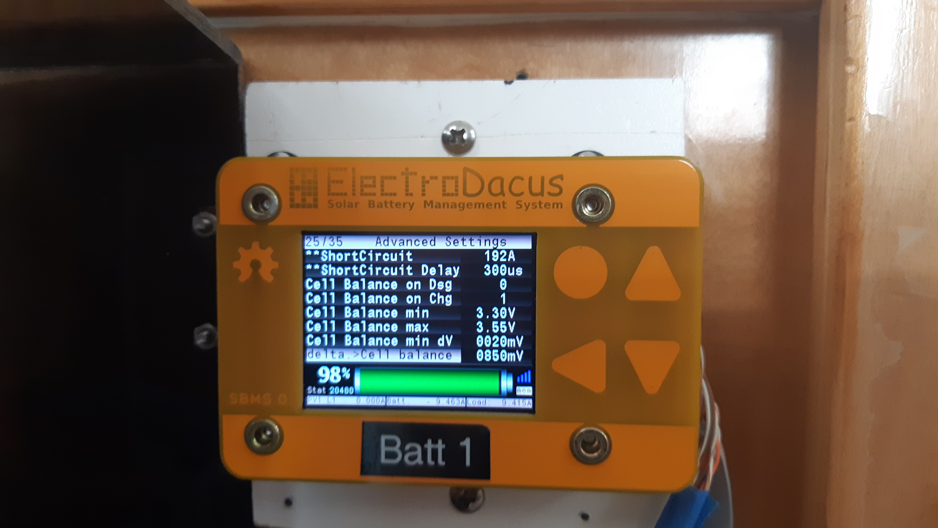
BTW, Jim Fowler, there IS a MAX Delta, which on ours is set to 850mV. I assume that's the default.  Maybe that's why you are not balancing??

Jim Fowler

unread,
Jun 24, 2021, 11:46:08 AM6/24/21
to electrodacus
Mine is set to the default of 850mV as well.

Dacian Todea

unread,
Jun 24, 2021, 3:24:41 PM6/24/21
to electrodacus
Jim,

Please set the cell balancing minimum voltage back to 3.2V as default (you will need to power cycle for that to take effect). Cell balancing will happen as long as all cells are above 3.2V and there is at least a 12mV delta and also there is a charge current of at least 300mA. There may be other factors but this are the important ones.
You can not just change a single value in the Advanced parameter settings as all those are interconnected and you need to understand all of them in order to do changes.

Sherry,

When you enter Parameter settings then Advanced parameter settings all those values there are the current value stored in the EEPROM memory. If you do not see 3.3V and 15mV there it means you forgot to push the Store Parameters button after you made the changes. If make setting changes and then get out of the Parameter settings menu the changes will not be saved and when you enter again the data shown will be read from EEPROM
If values are there in EEPROM then when you power cycle (leave at least 2 or 3 seconds power OFF) then EEPROM memory content will copy to a working RAM memory from where they are used.


If you made changes and not sure what you changed you can always just select battery type (say type 1) push OK to confirm and all default value will be loaded then push the Store Parameter buttons let that finish writing and then power cycle the SBMS.  There is normally no reason to make changes to the Advanced parameter settings as those where selected by me for best performance and cycle life especially for LiFePO4 as that is what I use and I have the most data about.

Jim Fowler

unread,
Jun 24, 2021, 4:44:31 PM6/24/21
to electrodacus
So you are telling me that I cannot set the balancing at 3.4 volt instead of 3.2 without changing something else?  3.2 is really low and creates unnecessary balancing as it tries to balance cells that when it hits the knee are actually the lower soc cells and should not have been being balanced down.  I set it to 3.4 so that I can set my solar charge controller to 27.5 volts with a 2 hour absorption.  This should allow for optimal balancing and max SOC without overcharging at too high of a voltage.

Why would setting the min voltage to 3.4 cause the balancing to stop all together, that makes no sense.

BTW, it comes across much better to not assume people asking for help are complete idiots.  Rather than giving a response like above, which basically says you don't know what you are doing just set it to my defaults and don't touch, it would be nicer to give the details of what settings you thing need to be changed in conjunction with the low balance voltage setting and why.  I originally bought this BMS because I thought it would be far more flexible and allow me to fine tune various settings, but am finding, based on comments like you made above, that it is very inflexible and must be left at default settings or it does not function.

Some guidance and documentation on exactly what triggers balancing to start and stop, because it is obviously more than the min and max voltage and delta settings, would be great!  All day today I have been trying to get balancing to trigger again so that I can try and balance out the 2 cells that are a bit above the others and I cannot get it to trigger.  It was balancing initially this morning until one of the cells triggered the over voltage at 3.55, now it will not balance anymore even after resetting the parameters to the defaults and power cycling the BMS.  I've tried power cycling multiple times today and have resorted to manually attaching a load to the high batteries to bring them back into balance.  Is there a minimum battery or cell voltage that has to be triggered to reset the balancing ability?  It seems that over night when my batteries drain down a fair amount that balancing is once again enabled until it hits the 3.55 over voltage trigger and then does not balance again until I power cycle the BMS after it drops below a certain voltage or something.  Do you have detailed documentation on the charging and balancing logic and parameters?

Barry Timm

unread,
Jun 24, 2021, 5:00:33 PM6/24/21
to electrodacus
Wow, someone seems to have a very thin skin, and apparently feels the right approach to making changes is to make them BEFORE fully understanding the implications of those changes.
FWIW, my system is on fully default settings and the balancing works perfectly, just as yours would if you did not adjust things you don't yet understand.
My suggestion is to ASK FIRST to get the right level of understanding of all the interconnected parameters, and then decide on what (if) you want to change for some reason. 
That way, you retain a perfectly working system until you decide to "fine tune" it further. 

Dacian Todea

unread,
Jun 24, 2021, 5:16:16 PM6/24/21
to electrodacus
Jim,

You can check the ISL94203 datasheet if you want to fully understand how the parameters relate to each-other  https://www.renesas.com/us/en/document/dst/isl94203-datasheet  all that is done in hardware.
I do not have the time to get in to all the complex details that is why I prefer to say use my default settings.
SBMS0 should have remote ON/OFF control over all charge sources and separately over all Loads else it can not protect your battery. So your solar charger should be controlled ON/OFF by the SBMS0 EXT IOx set as type 1 that way when any cell gets to 3.55V (default settings) the charging will completely stop and only start charging again when all cells drop below 3.4V or SOC drops under the set level depending on your selection.
Absorption and float charging are detrimental to all type of Lithium cells including LiFePO4.

Jim Fowler

unread,
Jun 24, 2021, 5:26:44 PM6/24/21
to electrodacus
Yet again someone operating from the position of they are the smartest and everyone else is an idiot.  Your comments were completely unhelpful and unnecessary.  You have no understanding of what I do, or do not, know.  You have no knowledge of my experience, training, or even what my setup is, yet feel the need to claim I don't know what I am doing and just need to set things to default and leave it alone.  I've had many perfectly working systems for many years, and I have more understanding than most of how many types of batteries, chargers, solar, and BMSs work, and electricity in general.  This particular BMS appears to not behave strictly according to set parameters and has hidden logic, hence why I am asking for further details and understanding of the logic and parameters as I "fine tune" it further.  I have rather thick skin and really couldn't care less, I threw that out there as I have heard from quite a few in other forums to not even bother with this BMS because of this kind of unhelpful attitude.  I was hoping to create awareness is all, sorry to have shaken your view of superiority a bit.

Jim Fowler

unread,
Jun 24, 2021, 6:29:44 PM6/24/21
to electrodacus
Thank you for the link to the documentation, that does help a lot!  I'm assuming that for the balancing you are using the internal state machine and not an external microcontroller as it states is possible?

Jim Fowler

unread,
Jun 24, 2021, 7:28:55 PM6/24/21
to electrodacus
As documentation for others who may face this issue, here is what I discovered from the documentation.

The reason that setting the min balance voltage to 3.4 stopped balancing from happening is because balancing does not actually trigger at the min bal voltage setting.  According to the documentation it triggers at min bal vol + 117mv.  This changes everything!  By setting the min bal vol to 3.4 it actually won't trigger until 3.517, which is just a few seconds before it hits the cutoff of 3.55.  This does not give it enough time to actually trigger the balancing.  So you actually need to set the min bal vol to 117mv less than what you want balancing to trigger at.

Dacian,

According to the documentation there is a bit,  CB_EOC, that does the following:

The CB_EOC bit provides an exception to the cell balance current direction limit. When the CB_EOC bit is set, balancing occurs while an end of charge condition exists (EOC bit = 1), regardless of current flow. This allows the ISL94203 to “drain” high voltage cells when the charge is complete. This speeds the balancing of the pack, especially when there is a large capacity differential between cells. Once the end of charge condition clears, the cell balance operation returns to normal programming.

Would you possibly be willing to expose this bit in the menu, or is it already there and named something different?  I believe this would be beneficial for the use case that I have.

Regarding your comment that absorption and floating is always detrimental to LiFePO4 cells.  This is true if you are charging to 3.55+ volts.  However, if you have the luxury of taking more time to charge your cells you can charge to a lower voltage, say 3.45, and then apply absorption for a period of time.  This allows a finer grain of control over the balancing as you can do it for a longer period without over charging the cells.  This not only will not cause damage, it will lengthen the life of the cells.  You can in fact achieve full SOC on a cell by charging at only 3.35 volts for an extended period of time even.

Barry Timm

unread,
Jun 24, 2021, 7:52:38 PM6/24/21
to electrodacus
I believe that in your anger you got Dacian mixed up with my reply. At no stage has he said or implied that you're an idiot. Nor did I, for that matter. Although it's heading that way fairly quickly, given the tone of your responses. 
PS You will not find better technical support for a product than right here, from Dacian. If you think otherwise then you ARE an idiot, shooting your mouth off with very little experience of the product or its support. See, I said it! LOL.  Dacian is a more patient man than I.

Good luck. I've said my piece here, so long.

Dave McCampbell

unread,
Jun 24, 2021, 10:11:41 PM6/24/21
to electrodacus
Jim, very helpful to get your explanation of why we are not balancing consistently when start balancing voltage is set much above 3.2vpc.  We have been wrestling with this since early on when we discovered, as you have, that the cells don't maintain their relative voltage positions during charging.  As Sherry noted earlier, we have resorted to manually balancing when necessary to get our cells to a minimum delta at charge termination.  Looks like you do the same.  We will probably reset our start balancing back to 3.2vpc now and see what happens.  If it does not work we can always turn balancing off, if necessary, but it does seen to work for many installations. And thanks to Dacian for sticking with us on this.  Now we know the why details behind your advice. which is always helpful.  

Also, our understanding is the same as Dacian's and yours that any absorption at higher charge termination voltages is detrimental because the cells are already at full state of charge when they get there, especially if charging at lower C rates.  However, at lower charge termination voltages, there may be some room for absorption, assuming there is some need for more charging time.  How do you determine how much absorption is safe?  I would think monitoring tail current is better than just time?  

Barry, your comments are not helpful to this discussion.

Jim Fowler

unread,
Jun 24, 2021, 10:55:06 PM6/24/21
to electrodacus
Dave,

You may also find it useful to know that I discovered today that while the initial trigger of balancing doesn't start until 117mv past the min bal vol setting. If the overvoltage setting has not been triggered before the battery drains it will start balancing again at the actual min bal vol setting.  If, however, the over voltage setting has been triggered, it will not trigger balancing again until 117mv above the min bal vol setting.  Odd and irritating behavior.  It basically assumes, as Dacian hinted at before, that you are not using the BMS for battery protection, but as the actual charge controller.  It's fine if you know the behavior, and why.  I don't know why people get so touchy around here when you ask for details on the why...

Jim Fowler

unread,
Jun 24, 2021, 11:55:54 PM6/24/21
to electrodacus
To answer your question about determining the absorption time and voltage without causing damage, that comes from analyzing the charge characteristics of the cells.  Off grid garage has some good basic videos on the process.  Unfortunately without coding the logic into an external charge controller you basically have to run an analysis of your cells and determine the proper absorption time at the voltage you want to use.  I chose a voltage and time that still leaves a few ah on the table so that I don't risk damaging the cells.  Alternatively you can just use the sbms defaults, and then top balance the pack if you notice cells drifting too much.  Personally I hate tearing my pack down to rebalance, even if it is just once a year or so.  Plus I like the challenge of seeing if I can get the most from the pack without ever having to balance, or damage the cells.

Barry Timm

unread,
Jun 25, 2021, 12:39:30 AM6/25/21
to electrodacus
"We will probably reset our start balancing back to 3.2vpc now and see what happens."

I will be extremely surprised if the result of reverting back to default balancing parameters is anything but a well-balanced pack. 
My own little 7.8 kwh pack 8s2p of 16x 150ah aluminum cased cells is ALWAYS balanced to within the default 11mV delta, on every charge cycle. It is often at 8mV or 9mV between the 8 groups of cells.

I'm curious what problem you are trying to solve that the default settings is not appropriate for...?

Barry Timm

unread,
Jun 25, 2021, 12:44:44 AM6/25/21
to electrodacus
Screen Shot 2021-06-11 at 7.52.18 PM.png

Barry Timm

unread,
Jun 25, 2021, 1:44:46 AM6/25/21
to electrodacus
Jim, I apologize for my remarks. I guess I got defensive and responded to what I saw as rude and accusatory tone in your post(s), but that should not have elicited the kind of response I provided.

Barry.

Jim Fowler

unread,
Jun 25, 2021, 2:57:34 AM6/25/21
to electrodacus
No problem.  There was some frustration in my posts as I was tired of getting the response of just set it to default and leave it.  We did finally get the details I was looking for and all is good.  To answer your question on what use case would require an extended balance period like I described, it is when you have a high rate of discharge/charge with large packs.  If there is even a slight difference in internal resistance, it will show it's face under high discharge/charge conditions and with large packs the 1 amp balancing is not enough to keep them in line and the cells will slowly get out of balance.  For this situation you can either go with an active balancer that will balance at a higher rate, or keep the batteries in a balance condition for an extended period of time with a very slow charge rate so that the passive balancing can be at least somewhat effective.  I will honestly probably go back to an active balancer for this pack as it is just too large for the passive balancing to be very effective, and the active balancer moves the energy around rather than burns it off to balance.  There are pros and cons to everything though... 

Dacian Todea

unread,
Jun 25, 2021, 3:01:21 AM6/25/21
to electrodacus
Jim,

Yes the ISL94203 is in control as it will make sense since it will be much safer than a software solution. The IC was designed by a large company and tested significantly more than I can.  As you looked at the spec you understand that there are many relations and so many possible causes for your cell balancing not being active.
Your problems are probably because you do not use the SBMS0 the way I designed and that means SBMS0 is in charge or charging and discharging and has remote ON/OFF control over all charge sources and also separate control over all loads.
In that case those 117mV deltas will not affect you because charging will stop when any cell gets to 3.55V (default limit) and charging will be re-enabled only when all cells dropped below 3.4V or SOC dropped below the limit you set in the DMPPT Settings if that is different form 99%
I think is counterproductive to do cell balancing while discharging. Since top balancing is the ideal type of balancing then cell balancing should be done only during charging.
The reason one of the cell will have higher voltage than the others (assuming cell started perfectly balanced at some point)  is because that cell has slightly lower capacity (that is OK as all cells can not be perfectly equal) and or higher internal resistance. So the cell with slightly higher internal resistance (to this contact resistance can be added) will have a higher voltage drop than other cells and that will add to cell voltage when charging the cell so that cell will be reading a higher voltage thus cell balancing will be active and reduce the charge current for that cell (say charge current is 500mA and balance current is 120mA then that cell will see only a 380mA charge current while the lover voltage cells will see the full 500mA)
Now say charging stops and there is a discharge current but you want to continue to balance. In that case this cell with higher internal resistance will have lower cell voltage than the others due to that extra voltage drop that will this time subtract from the cell voltage so the other cells will be balanced and this cell will not making this counterproductive.
   
It takes only seconds at typical solar charge rate for a cell to get from 3.45V to 3.55V. And for battery longevity is best to charge to 3.55V even 3.65V and then stop the charging than to absorb at very low current or float around 3.45V (not that it will even be possible unless current is equal or lower than cell balancing current that is fairly small).

I posted the below graph showing typical voltage vs SOC on LiFePO4 many times on the forum.  It shows fairly clearly that unless you have perfectly equal cells in your pack (just not possible with current manufacturing tolerances) the cells will start to drift in voltage when very close to 100% SOC and that is just normal. This is also the reason the BMS needs to have charger control as is the only one knowing each individual cell voltage and can protect all cells in the pack from exceeding a set limit like 3.55V
In many cases you will have 7 cells around 3.4V when one of the cells will get to 3.55V (usually in less than a minute).  With other type of Lithium batteries like LiCoO2 or NMC the charge discharge curve is much less flat and there you can maybe use different strategies and those cells will be way more equal in voltage even at the end of charge but those type of cells are just not as suitable for solar energy storage as LiFePO4 as they have much lower cycle life and also those cells degrade way faster if maintained for hours around 100% SOC. 

LFP.gif


Jim Fowler

unread,
Jun 25, 2021, 6:51:26 PM6/25/21
to electrodacus
I completely agree that balancing on discharge is not
 desirable for a top balanced battery.  My request to expose the parameter for discharging at eoc is not to balance on discharge.  The 117mv delta is actually more important to understand when allowing the BMS to control the charge as it will come into play every time the BMS triggers the 3.55 over voltage. Which means that balancing does not actually kick in at the voltage you set in the parameters, but 117mv above that voltage.  So really to achieve the 3.4 balance voltage that I desire, I need to set it to 3.283.  Then in this case, have the mppt kick into absorption mode.  This is only needed when it is noticed that the pack has become unbalanced, to bring it back into balance.  90% of the time I would run it with your default settings, minus having the balancing kick in at 3.2 volts as that is far too early in the flat charge region where it is just beginning the charge and will result in false positive balancing.

You commented that it only takes seconds to go from 3.4 to 3.55 volts while solar charging.  This totally depends on the amperage you are pumping into the batteries, and the size of the pack.  Mine takes many minutes to go from 3.4 to 3.55, even at 70-100 amps charging rate.  Much of the time there are high loads on my system at the same time it is charging so it is only charging with around 30-50 amps.  It all just depends.

Dacian Todea

unread,
Jun 25, 2021, 7:29:31 PM6/25/21
to electrodacus
Jim,

Not sure why you will want to only start balancing at 3.4V and not much earlier ?
Those are voltage limits where cell balancing is allowed and so if cells are all above 3.4V  cell balancing is enabled but if at any point any of the cells dropped below 3.4V then the 117mV hysteresis is needed to enable cell balancing.
So say you where below 3.4V cell balancing will start at 3.517V and then if say charger is disabled and lowest cell drops to 3.401V then you re-enable charger the cell balancing will work even with that 3.401V cell but again my default voltage for Over voltage recovery is set at that exact 3.4V so charge will restart only when all cells drop below that value so clearly the cell balancing will be disabled if max cell balance is set at 3.4V
You can increase the cell recovery voltage but I think even at 3.4V is high enough thus the reason I usually recommend setting a SOC limit like at least 95% so charge only restarts when SOC is below 92% and stops at 95% after the first full charge of the day. This way the battery is not maintained for the entire day at 100% SOC or very close to that.

If there is a large difference between cells maybe just installed pack or larger difference in cell internal resistance coupled with relatively large charge current it is helpful to have hours to balance that higher SOC cell or as may be the case higher internal resistance cell thus the reason I selected 3.2V.  If the cells are nice and balanced and fairly equal internal and contact resistance then there will be no delta until close to fully charged (less than 11mV default) and so no cell balancing will be performed.
You can be above 3.2V even at 20% SOC so there is plenty of time for cell balance to work if it is needed and if it is not then there will be no balancing done thus I do not understand why you want to increase the cell balance minim voltage from that default 3.2V
You can not say 70 to 100A charging if you have a load at the same time that uses big part of that as that PV (assuming this is from solar PV) power will directly supply the load and SBMS measures battery current so it will see the 30 to 50A you used as example. Not sure if you mentioned your battery capacity and the internal DC resistance will also be important but is typically just around 1% SOC from 3.4V to 3.55V so so say you have a 500Ah battery with good internal resistance and good contact resistance then it will take about 60 seconds to get that 1% SOC at 50A charge current.
Of course with say 10A in same example it may take 10 minutes but still when one of the cell's starts to get away from the others is just at most a minute or two before it gets to full charge 3.55V in this case.

Dave McCampbell

unread,
Jun 25, 2021, 11:47:19 PM6/25/21
to electrodacus
Jim, thanks for continuing to Sus out the why of all this.  It sure helps us make informed decisions.  We are still experimenting with some settings both on the SBMS0 and our two MPPTs, one installed and one spare.  We have a 12v electrical system on the boat and 24v panels purchased before the LFP install.  So we need the MPPT.  Wish we did not, as it puts another piece of electronics between being able to charge our cells and not, without having to resort to rotating machinery.  If we had it all to do over again we would certainly use 12v panels with our 12v electrical system.  The reliability of being able to use DSSRs instead of expensive MPPTs is certainly worth a few amphours difference a day.

Barry, we find a big difference between cell deltas at rest and at charge termination.  We are trying to get the cells as close as we can at charge termination, not just at rest.  Our cells also have a delta under 10 mv at rest, as your SBMS0 photo above shows.  With the Node Red display we have it is a bit scary seeing one cell charge curve shoot up as the cells approach charge termination even if the SBMS0 will terminate the charge before damage is done.  What delta are you seeing at charge termination and can you see what the cells curves are doing during charging?

Dacian, we have the same issue as Jim with starting balancing too early in the charge.  We can see, using our Node Red display, individual charge curves, which you cannot see with just the SBMS0 displays.  On the way up some of our cells change delta positions high and low.  So a cell that is high at the start of the charge may end up being low at charge termination.  If the balancer is trying to lower a high cell's voltage initially, and that cell would have been low at charge termination, the action of the balancer is counterproductive.  So, like Jim, we have tried to limit the balancing to the latter stages of charging when the cell positions high and low are relatively steady.  We know that this limits the time the balancer has to act on the cells, so if the deltas get too great we can use our adjustable load to manually adjust cell voltages.  Jim described a similar situation above.  

We are not in a hurry to resolve this, so will see if the SBMS0 balancer can get our deltas under control using your defaults.  We are pretty sure that the cell voltage variances we are seeing are a result of less than perfectly matched cells at the factory.  I don't know how they could perfectly match cells without spending lots of time at it.  And time eats into their profit. As you mentioned cell internal resistance and resistance in the connections contribute.  So it would be really hard to find even as few as 4 cells have the exact same charge curves. 

Great discussion here.  We are learning a lot.  

Barry Timm

unread,
Jun 26, 2021, 12:19:33 AM6/26/21
to electrodacus
"Barry, we find a big difference between cell deltas at rest and at charge termination.  We are trying to get the cells as close as we can at charge termination, not just at rest.  Our cells also have a delta under 10 mv at rest, as your SBMS0 photo above shows.  With the Node Red display we have it is a bit scary seeing one cell charge curve shoot up as the cells approach charge termination even if the SBMS0 will terminate the charge before damage is done.  What delta are you seeing at charge termination and can you see what the cells curves are doing during charging?"

I'm not interested (except for curiosity sake! :-) ) in the voltage delta at charge termination, as it's my understanding that it is perfectly normal for one or two cells to jump up in voltage at that steep end of the curve, right at the end of charging. So, for me, there is nothing to be gained by trying to manipulate what is usually a few seconds of voltage variance. It is meaningless to me. I am much more concerned with the desire to have all charging stop whenever any one cell reaches 3.55v and that I have confirmed by closely watching the system after it reaches 99% SOC, until charging terminates.

Secondly, I am concerned about the cell voltage deltas being minimal during actual loads (between charge cycles), and again, this is managed exceptionally well, to me. I see very little voltage delta in use. I was starting to see some deltas developing on a specific cell about 6 months ago, and with Dacian's advice, found it to be a poor connection on one of my cell busbars (loose nut) and then also a badly crimped cell signal wire on one cell. As soon as I resolved those two "user" issues, the system balancing worked perfectly again.

Perhaps I'm missing the point of concern regarding the voltage deltas a end of charge. Can you explain the concern further? I could eaily be missing something here.....

Lastly, could you offer some details on your system...battery capacity, configuration, average loads, PV etc?
Also, how long have you been running the system with the default settings? Did the system not stabilize balancing over a period of time? 
Did you parallel connect all cells prior to SBMS0 startup, for a good starting point synchronization balance?

Dacian Todea

unread,
Jun 26, 2021, 1:56:57 PM6/26/21
to electrodacus
Dave,

I do not remember but do you have a DSSR20 between panels and MPPT's  ? Or ar they some brand like Victron that has remote ON/OFF and is then SBMS0 controlling the charging that way?
You will never be able to get the cells equal at charge termination unless you have ideal cell with perfectly equal capacity, internal resistance and contact resistance or you slow down the charge at the end to same current as cell balancing current but that will be very slow and also detrimental to Lithium batteries.
You will have that maybe 0.1% SOC delta between cells as that can not be corrected unless charging as mentioned above but that cell delta will not increase as the cell balancing will maintain the pack in those limits.
As long as cells at rest are within 11mV (default cell balancing setting) cells will be OK and as balanced as they can be. If you see a large delta during discharge then as Barry already mentioned check the connections for that cell that shows a lower voltage during discharge as you may have a bad connection.
Also I do not want to sound rude as Jim at some point interpreted but using the default settings is the best choice unless you have very specific use case. I used LiFePO4 for about 10 years at this point so I have very good understanding on how the work and what will be the best general settings for longest life. Changing this default settings will make sense if you had a different type of application like for example you required fast charging or super high discharge rates but not for typical solar energy storage where charge rates are max around 0.25C and discharge rates usually below 0.5C.
Also you may require changes if you where to use other type of cells like NMC or LTO as I have less direct experience with those or I care a bit less about them as they are not as suitable for solar energy storage as LiFePO4


I took a look at your graph again where cell 2 was always at higher voltage but just slightly and then increased for the last half an hour or so and it just looks like directly proportional with the increase in charge current (seems to be in the morning) and if that is the case then you just have a bad connection to that cell 2.
It will have been useful to also graph the battery current but that is my assumption.

Barry Timm

unread,
Jun 28, 2021, 2:42:58 PM6/28/21
to electrodacus
Dave, you asked about my cell voltage deltas at eoc. I managed to snap a screenshot of the deltas almost exactly one minute after the End of Charge. The maximum delta between the cells was 7 mV.
Screen Shot 2021-06-28 at 12.38.50 PM.png

Dacian Todea

unread,
Jun 28, 2021, 6:12:11 PM6/28/21
to electrodacus
Barry,

It is not quite fair as you had a bit ore one minute of around 900W as load after charging has ended. People that see that higher delta usually have a very small load or even no load at all and then you will see some voltage delta as at least one of the cells is at 3.55V or a bit over while the others may be around 3.4V or slightly below so it is easy to see 100 even as much as 150mV delta at end of charge if there is no load at all at least for a few minutes but if there is a load especially a relatively large load then in just a few seconds the cells will drop all to some fairly equal value as it it your case.
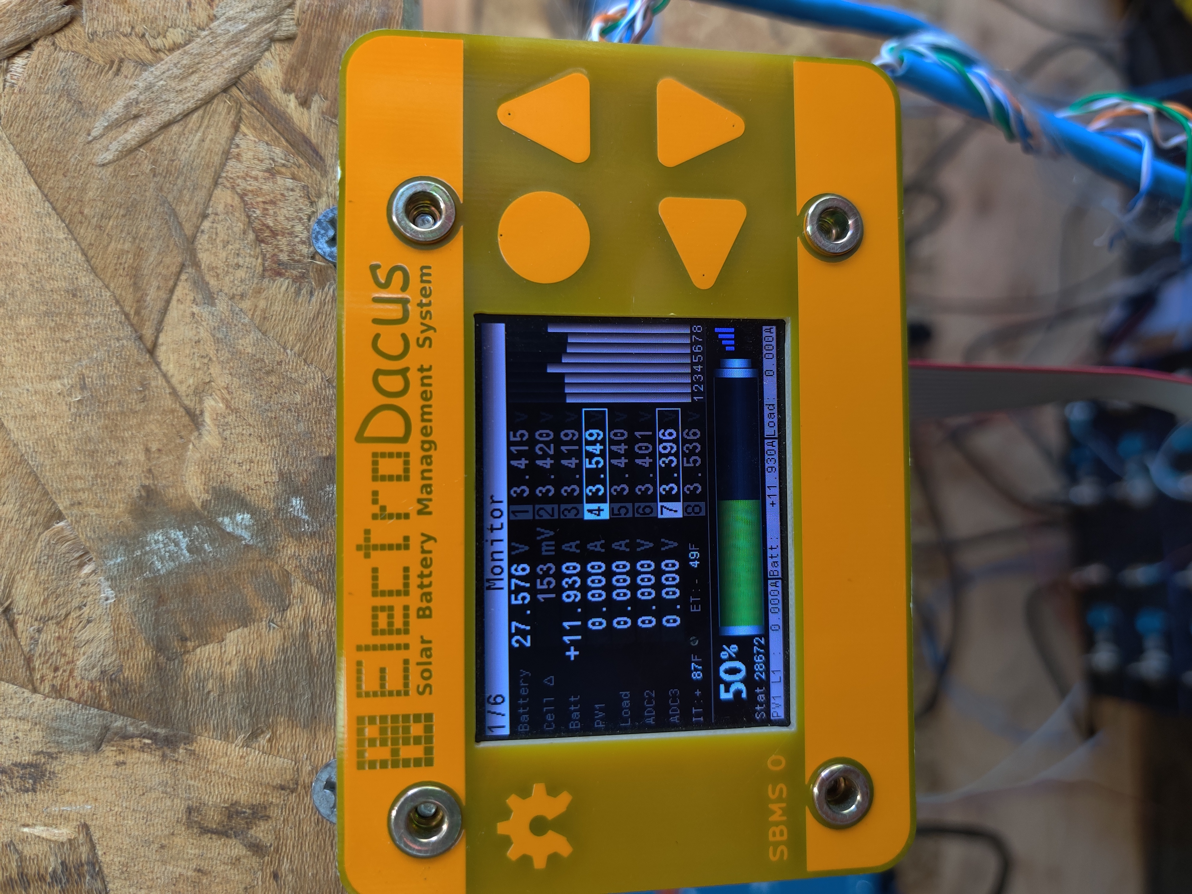
I do not want people to think that the most they will see as delta will be 7mV as it will be normal to see 100 to even 200mV delta at end of charge.

Barry Timm

unread,
Jun 28, 2021, 6:20:10 PM6/28/21
to electrodacus
I understand your concern with regards expectations being set, but how is even a 200mV (which I have never seen even close to that on my system) relevant when it is there for literally seconds (or even a minute or so) before it stabilizes again? 

It's surely not something that needs to be "actioned" as it is a very short term (seconds/minutes) characteristic of the end of charge of LFP cells in series. Why is this delta significant?


Dacian Todea

unread,
Jun 28, 2021, 6:35:28 PM6/28/21
to electrodacus
Yes 200mV is possible and yes that will only be for a few seconds.
Most cells will be around 3.4V at the end of charge and one of the cells will need to get to 3.55V in order for the charge to end. You have the old SBMS0 model and have the default settings set a bit different as the Over voltage delay is likely set to just 1 second so when any cell gets to 3.55V for 1 second charging will end. That will be the case even if the cell got to 3.55V due to cell balancing voltage drop being added to the cell so no cells will ever exceed 3.55V for more than one second and likely due to cell balancing current the charge will end without even having a cell get to 3.55V (just the fake reading including the cell balancing voltage drop).
On the newer SBMS0 since some complained about charging ending a bit to early especially for those with NMC batteries  I added 6 seconds as over voltage delay by default as that is higher than the 3 seconds cell balancing ON time and so the cell needs to be relay getting to 3.55V as the cell balancing voltage drop reading can not longer stop the charging as 6 consecutive seconds with above 3.55V are required for the charging to stop.
They can of course reduce the overcharge delay to 1 or 2 seconds and have the same sort of charging behavior like you where charging ends maybe 30 seconds to a minute sooner than in their case.

Barry Timm

unread,
Jun 28, 2021, 8:33:34 PM6/28/21
to electrodacus
"Yes 200mV is possible and yes that will only be for a few seconds."

That says it all, for me, thanks.
But I do appreciate the info on the different charging max voltage duration defaults. So, if I wanted to replicate the characteristics of the newer version, I could change a parm from 1 s to 6s? (Not that I want to.....as I'm very happy with the current setup, just curious).

Dave McCampbell

unread,
Jun 28, 2021, 11:24:16 PM6/28/21
to electrodacus
Barry.  We did two top balance sessions before activating the system.  It is 540ahrs 4S2P.  Average load 10a, max150a infrequent.  PV 800w 24v nominal, average about 40a, 58a peak current.  12v nominal system so need MPPT.  Have been working with system in operation for about 6 months.  Working with spare MPPT now that does not have sense wire so some interesting performance and voltage reading variations that make it turn off charging earlier than we want.  We will go back to our original Morningstar MPPT as soon as we get a good feel for what we will be faced with if we have to use the spare in the future.  Cruising boats always need spares, and it would be a lot easier if we just had 12v panels.  We are still testing different settings trying to understand the why behind them.

Dacian.  Thanks for sticking with us on this.  At your suggestion, early on we placed two DSSR20s between our panels and our single MPPT.  So the SBMS0 can terminate the charge if one cell goes high.  MPPT is rated for 60a max and panels are 72 cell 4x200w, so about 45A total rated output.  Have seen 58a mid day max, so good boost from the MPPT.  Average PV charge at 35a is about .07C charge rate.  Average discharge rate at 10a is about .02C.  We use about 150ahrs a day.

At rest during the day with just loads affecting the pack our cells are always within 10mv, but at charge termination our delta can go over 100mv.  We have had charge termination delta at around 20mv.  This is somewhat variable for reasons you stated earlier.  We have been successful at reducing that manually using an adjustable load.  So you are saying this is normal and acceptable as long as the SBMS0 can terminate the charge when one cell goes high?  And with that much delta the other 3 cells may be as low as 3.4vpc?  

But our SOC reads 99-100%.  Does that make sense?  I would think that the SOC with 3 of 4 cells at 3.4vpc and one cell at 3.55vpc would be lower, total equals 13.75v.  But maybe since all cells were so close during the charge up to the knee, when the one cell hit it first and quickly went to charge termination, the others were very close.  Then 99% would make sense.  This works out to be close to what we and others have used in the past by letting the MPPT terminate the charge at 13.8v, and if needed the SBMS0 is the safety net by terminating the charge if one cell gets to 3.55vpc.  Interesting.

We are now letting the SBMS0 balancer work at your defaults to see what it is able to do with our cell deltas at higher voltages.   It seems to be working at voltages above 3.317vpc, if cell deltas go above 11mv.  We I will have a look at cell 2's connections to see if that offers any improvement.

Barry Timm

unread,
Jun 29, 2021, 2:19:38 AM6/29/21
to electrodacus
"But our SOC reads 99-100%.  Does that make sense?  I would think that the SOC with 3 of 4 cells at 3.4vpc and one cell at 3.55vpc would be lower, total equals 13.75v.  But maybe since all cells were so close during the charge up to the knee, when the one cell hit it first and quickly went to charge termination, the others were very close.  Then 99% would make sense. "

No doubt, Dacian will explain this properly (and correct anything I say incorrectly! :-) ), but I believe this is precisely what you can expect from a normal working system. You have the last minute sudden increase in voltage of a cell as they approach 100% capacity. This delta grows suddenly and quickly, right at the end of the charge.

Personally, I am not concerned or interested in this delta, as long as the cells are protected by the charge being shutdown in time to prevent damage to any of the cells, and as long as the balance is within expected variance after the cells have dropped back off that "knee". In my case, because I am usually running an A/C, that drop is literally just a few seconds, and I see the SOC% drop almost immediately from 100% to 99%. I see this as perfectly normal due to the conservative charging level deployed as default, and on the other hand, I'm absolutely not interested in trying to cram a few more ah into the battery, to the detriment of longevity.

Barry.

Dacian Todea

unread,
Jun 29, 2021, 12:20:11 PM6/29/21
to electrodacus
Dave,

Those are 800W of panels so yes when they are cold and in full sun they should provide that or very close so 800W / 13V = 61.5A and with edge of cloud effect even more. Of course MPPT has some 5 to 7% loss so that will be subtracted.
If at high charge current is when you start to see a larger delta then it may be from a bad contact between cells so please check that.  As your discharge current is even lower it will be hard to check with that but when you have high charge current just stop the charging get a multimeter set on mV and measure the voltage drop across the connections while you have high charge current. You will measure by having the probes at the cell terminals that way you measure the voltage drop on the cell to bus bar connection both connections and if you see one with larger voltage drop you can check between that cell and the bus bar to understand exactly witch of the two contacts is bad.
That graph Sherry posted is way to gradual and likely flowing the increase in charge current that means that cell 2 had a bad contact. That can be one of the connections to cell 2 either positive or negative or connection to cell 1 positive or cell 3 negative depending where your cell sense wires are connected.

SOC will be 100% when any cell gets to 3.55V and beside that cells at 3.4V can themselves be above 99% SOC see this graph I posted many times on the forum.  What the graph shows is charge discharge voltage vs SOC and the exponentially fast voltage increase above 3.4V as cell is full and can no longer accept any electrons.  But in your particular case I think there is also the problem of a bad connection (high resistance connection around cell 2).
LFP.gif


PeterBC

unread,
Jun 29, 2021, 7:41:51 PM6/29/21
to electrodacus
Daican, 

Love your graph you've quoted many times. Out of interest what charge/discharge rates are those sample red and blue lines at ? I imagine the deltas could be significantly different at 0.05C vrs 1C ?  

Clearly raising the min balance voltage (of ALL cells) from 3.2 to 3.4 v will remove about 90% of available balancing time, esp since it stops charging (and hence balancing) as soon as ONE cell hits 3.55.  I think one source of confusion by some (inc me at times) was missing which limits were for ALL cells vrs ONE cell. 

I admire your patience with us all, and thanks for your outstanding support.

Peter

Dacian Todea

unread,
Jun 30, 2021, 12:09:39 AM6/30/21
to electrodacus
Peter,

Charge discharge rate will make little difference if any to that graph.  Increasing the charge/discharge rate the blue and red lines will be a bit further apart but it also depends on the cell internal resistance not just charge/discharge rate.

Plamen

unread,
Jul 3, 2021, 7:05:33 AM7/3/21
to electrodacus

      I've never took the time to watch how my cells behave, but since there's been a lot of talk about that lately here is my story. Bought my Winston LFP400AHA on 12.09.19 and received 23.09.19 from ev-power.eu.

Upon arrival, all cells (8 of them) were at 3,300 volts. It tooks me "only" 16 months to start using them (all was done in 7 days, the rest just preparation). Those 16 months cells stayed in the original box I’ve received them with no maintenance of any kind. The temp. for that time vary between 0 and 35 degrees. And the voltage was dropped to 2.28. Usually when i check the delta is below 11mv.

  I have no loads connected to Load+ and all ext. loads were off yet i have 1.8A load at 80A charging. Guess not calibrated that shunt well.
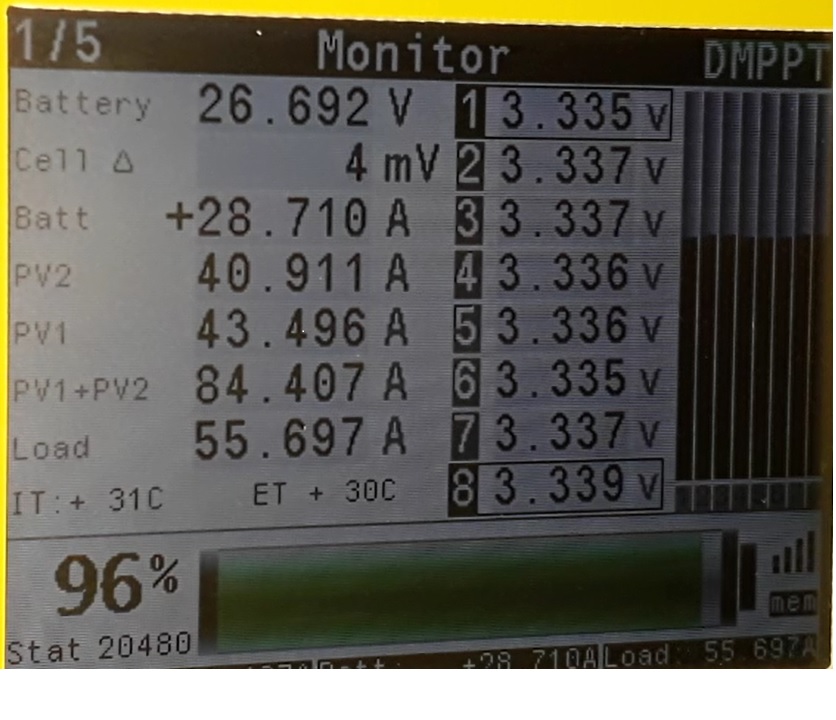
0.jpg1.jpg2.jpg

Plamen

unread,
Jul 3, 2021, 7:09:36 AM7/3/21
to electrodacus
I forgot to mention that I use the default settings.

Dacian Todea

unread,
Jul 3, 2021, 12:26:03 PM7/3/21
to electrodacus
Plamen,

Those look like perfectly balanced cells. It is a good example for others to see.
The charging rate was also as large as I max recommend around 0.2C and Winston are fairly good cells just a bit expensive compared to the very popular aluminium case cells from CATL,EVE ...


Plamen

unread,
Jul 4, 2021, 11:31:48 AM7/4/21
to electrodacus
Today i've noticed something. With the default settings balancing starts only when charging with more than 300mA. But those are on the PV shunt or the battery?discharge balancing.jpg
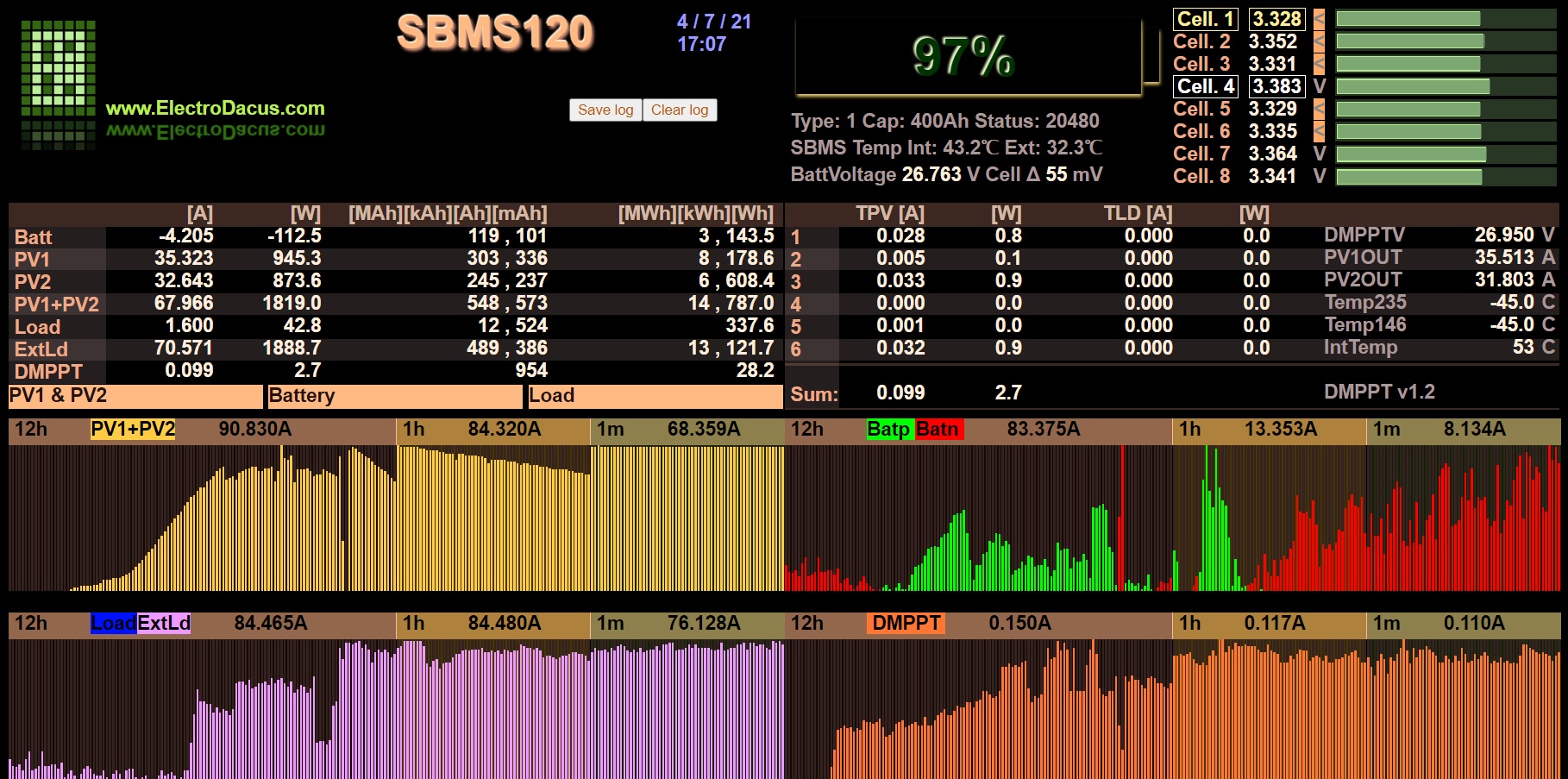
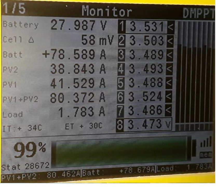
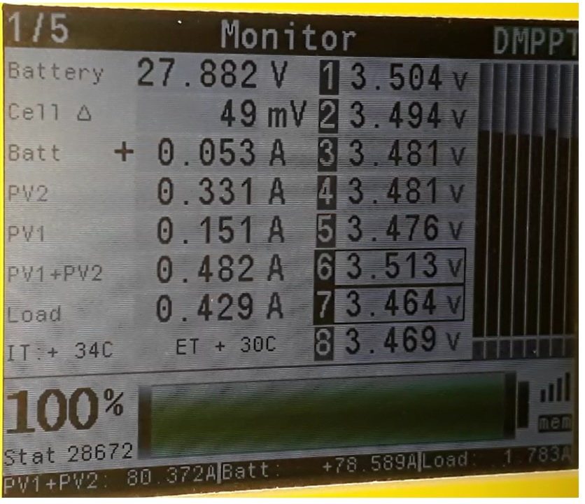
Load was bigger than PVs supply so battery was discharging but balancing is on.

Dacian Todea

unread,
Jul 5, 2021, 9:52:06 PM7/5/21
to electrodacus
You have an SBMS120 that is not designed the same way as the SBMS0.
The battery current is measured by the ISL94203 directly as it is trough the internal battery shunt on the SBMS120. If that exceeds about 700mA of charge current the balancing is enabled but the ISL94203 can not see the external current shunt that can only be measured by the microcontroller.
There is no good work around against this but I have not noticed any cell balancing problems on my battery as I also use an SBMS120 for the last 4 years and I also have external current shunt that powers my inverter. 
Tho you seems to have a bit of an unusual large load that is continues for some hours. Curious what sort of load will that be ?
Most high power loads are some sort of heater or coolers and they have a thermostat so they work intermittently to maintain a set temperature. 

Plamen

unread,
Jul 6, 2021, 6:31:40 AM7/6/21
to electrodacus
    It was the first time i've seen that and as the post is on balancing. Now i know that it's by design. Still battery is perfectly balanced. I'm not sure what was the load exactly. I have a 750W water distiller that switches off just when is done. About 4 Liters in 4 hours. Next is a water pump for irrigation. It's 750W too. Those are the two that run for hours usually. In addition some small dc loads.
     When charging stops and still there is a big load, noticed that every few seconds some cells jump from the real 5~8 mV delta to 60~120 mV for less than second. I don't think it's real data but just to be sure that there is nothing wrong too.

delta spikes.avi

Dacian Todea

unread,
Jul 6, 2021, 1:20:35 PM7/6/21
to electrodacus
Plamen, 

I have the same water distiller and that can not be responsible for  70A at 26.7V =  1870W but if the pump was also working at the same time then yes that will explain it.
Is nice to have so much water that you can use the pump to irrigate for hours :)

Plamen

unread,
Jul 6, 2021, 1:48:41 PM7/6/21
to electrodacus
Dacian,
   I forgot to mention that a video is attached in the post above. Could you check it, just to be sure all is ok. 

1625593109879.jpg

About the well, sometime it scares me. That pic. water level is at 150 cm. from the ground

Dacian Todea

unread,
Jul 6, 2021, 6:21:13 PM7/6/21
to electrodacus
Plamen,

I did not notice the video but looked now and yes all is perfectly fine. The inverter is either 50 or 60Hz so current to battery will vary between 0A and 1.4x the average current that is around 70A to 110A in the video so current at battery will 0A to 155A and look like a 100 or 120Hz half wave thus this will produce quite variation of voltage drop and since SBMS measures each cell voltage at a time fairly fast as there are 8 cells and many measurements per second for short periods then it averages a few of those but sometime when one of the cell is measured (sampled) it happens that a few consecutive samples read at the peak or bottom of the voltage spikes and so it just presents you for a few moments a wrong average measurement.   

That is a very high water table. Here is super low and a well will be expensive to drill so I use collected rain water. Also the well water will not be good for irrigation as it is to hard and soil is already not great.

Plamen

unread,
Jul 6, 2021, 7:04:26 PM7/6/21
to electrodacus
    I thought it's ok just didn't know WHY. Since 15th of january i haven't switched off my inverter or house water supply pump. Before i had to do that at night to save power. Second PV array is installed just have to do the cabling, so i'm getting ready for the winter.

  210702 093315.jpg

           Thanks for all your work and support here!   Take care and I wish you plenty of rain up there.
Reply all
Reply to author
Forward
0 new messages