AC Charging
208 views
Skip to first unread message

Tim D.
May 1, 2021, 1:45:34 PM5/1/21
to electrodacus
I know the SBMS0 is really made for charging via solar, and in normal/ideal conditions this seems pretty straight forward and easy to setup with the DSSR20's but I'm wondering how I can go about charging my batteries during an extended bad weather situation
For Example, could I use a small generator and an AC charger like the PowerMax PM3-100 https://powermaxconverters.com/product/pm3-12v-series/?
Since the DSSR20's are only able to switch 20 amps could I use the SBMS0 to turn on/off an automotive 120A relay to turn off the PM3-100 once the batteries were charged?
or is there a better way to use a generator provided AC charging method for extended bad weather

Dacian Todea
May 1, 2021, 1:55:49 PM5/1/21
to electrodacus
You can find a grid charger that has remote ON/OFF option or use maybe an AC SSR controlled by EXT IO4 to switch the AC input ON/OFF to stop the charging.
The EXT IO4 can switch max 50mA so can control a SSR that only needs about 10mA to control but cannot directly control a mechanical relay.
I do not have a generator as I sized my PV array to deal also with bad weather. PV panels generate energy at a cost amortisation of just $0.02/kWh while a fuel based generator costs at least $1/kWh so 50x more.
Tim D.
May 1, 2021, 2:14:20 PM5/1/21
to electrodacus
Thank you for the reply,
Yes, I know it's not ideal to use a generator, and if this was a power system for a cabin I could size the battery bank and solar panel array to deal with bad weather, but I'm looking at installing the SBMS0 into a lithium battery bank in a small travel trailer, so unfortunately the space I have for solar panels and batteries is limited, and a small generator seems like the best fit for a backup
Do you know of any AC chargers that I could use with a generator?
Any idea if this charger would work with your SBMS0? it appears to have a remote on/off built into it https://www.amazon.com/RSP-1000-15-Single-Output-Function-Supply/dp/B072TSRHKS/ref=sr_1_4?dchild=1&keywords=RSP-1000-15&qid=1619892597&s=electronics&sr=1-4
Dacian Todea
May 1, 2021, 2:22:34 PM5/1/21
to electrodacus
Yes that RSP-1000-15 has remote ON/OFF and can be controlled by the SBMS0 https://www.mouser.ca/datasheet/2/260/RSP_1000_SPEC-1511917.pdf
Tim D.
May 1, 2021, 2:50:25 PM5/1/21
to electrodacus
Awesome, thanks again for the input
If I'm reading this right I would use
EXT IO3 on the SBMS0 (I have the older version v02b) and then hook this up to Pins 2 and 6 on the charger
What settings would I need to change in the SBMS0 to get it to remotely turn off the charger once the BMS senses a max cell voltage of 3.55V

Jhon
May 1, 2021, 3:43:55 PM5/1/21
to electrodacus
Hi Tim,
Type 1 does the disconnect on charging. You might find this link helpful.
Tim D.
May 1, 2021, 4:27:28 PM5/1/21
to electrodacus
That's exactly what I needed,
Thank you
Tim
Dacian Todea
May 1, 2021, 4:30:42 PM5/1/21
to electrodacus
Tim,
By default the EXT IO3 is set as type 2 and used to stop a Load like maybe an inverter or DC loads.
The EXT IO4 is set as type 1 by default and that will be used for charge sources and yes that will connect to Pins 2 and 6
Pin 6 will connect to EXT IO4+ and pin 2 to EXT IO4- then you can set the EXT IO4 as type 0 to test that charger is turned OFF then if all works as expected set back to type 1 to enable charging.
Tim D.
May 1, 2021, 5:26:33 PM5/1/21
to electrodacus
Gotcha,
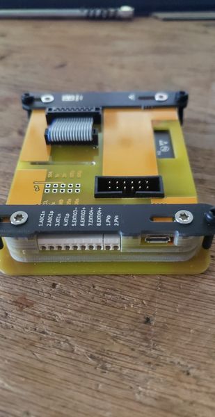
That brings up another question, Since my SBMS0 is the older version with Wifi (pic attached) , I only have two EXT IO ports I can use, (#3 and #4), so I don't have 4 EXT IO ports (#3, #4, #5, and #6) like the newer version has
Would I be able to control a DSSR20 (for my two 175 watts solar panels) and the AC charger off the same EXT IO4 port? or would I need to Upgrade to the newer SBMS0 since I will need reserve the EXT IO3 port for my inverter?
Thanks again for all the help
Tim
Dacian Todea
May 1, 2021, 5:36:27 PM5/1/21
to electrodacus
Tim,
You may be able to control both the DSSR20 and the AC charger from the same EXT IO4 but not sure it depends on how the remote ON/OFF is implemented on the RSP-1000 and as far as I can see they may just have a 5V or so logic level on the pin 6 and then that is pulled to GND (pin2) to enable the charger so different from the DSSR20 but you can have external optoisolators one for each device and then you can control as many charge sources as you want just with the EXT IO4
But maybe is simpler for you just to solder wires to EXT IO5 and set that in menu as type 1 to control the AC charger

DavidS
May 1, 2021, 7:11:20 PM5/1/21
to electrodacus
Tim, the way many folks deal with this is by using a remote controllable inverter/charger like a Victron Multiplus. All power runs through the multiplus, which then acts as a transfer switch, taking 120v ac in, passing it through to the coach when connected and charging the batteries as appropriate. Of course, Victron gear is on the higher end of the price range, but it's highly configurable and very high quality. That said, there are much less expensive options, some of which are listed in the SBMS0 manual. That said, I am currently using the SBMS0 to control an external relay, as you've described. In my case, it's controlling a load, but the same principle applies. It's just necessary to get the appropriate gear in place.

SolarChain
May 1, 2021, 7:50:19 PM5/1/21
to electrodacus
Not entirely correct ... if you have power sources such as an MPPT controller in addition to the Multi you would have two sources of charging each independent and each typically unaware of when the other is charging. A BMS could control each of those charging devices via signaling wires to aux inputs but those devices are technically independent of each other i.e. one doesn't run through the other.

DavidS
May 2, 2021, 4:08:00 PM5/2/21
to electrodacus
Of course, you are correct in that the scc doesn’t run through the inverter. Poor choice of words on my part. What I was suggesting was all AC power goes through the multiplus. Regardless, the sbms controls all charge sources.
Tim D.
May 3, 2021, 12:29:37 PM5/3/21
to electrodacus
Appreciate all the help
Looking at the RSP-1000-15 https://www.meanwell.com/Upload/PDF/RSP-1000/RSP-1000-SPEC.PDF, it seems it will only produce 750 watts of power, so is there any reason to select the RSP-1000-15 over the RSP-750-15? It looks like both will give me 50 Amps of charging
I notice the remote on/off switch is a little different with the RSP-750-15, using pins 13 and 14, vs 2 and 6 https://www.meanwell.com/Upload/PDF/RSP-750/RSP-750-SPEC.PDF, but I'm assuming the SBMS0 will still be able to control the RSP-750-15 like the RSP-1000-15
Also it seems like the RSP-750-15 will be a little more efficient than the RSP-1000-15 so as long as the remote can be operated by the SBMS0 I think this will be the charger I go with
Again, appreciate all the help, you guys are great
Tim
Dacian Todea
May 3, 2021, 12:46:07 PM5/3/21
to electrodacus
Tim,
The remote is slightly different but both will work with SBMS0.
Someone reported that on the RSP-750 the remote works but if you unplug from the AC and plug back it stops working until DC is disconnected and then reconnected. Maybe the RSP-1000 will not have this problem as it has current sharing capabilities.
Tim D.
May 3, 2021, 1:46:46 PM5/3/21
to electrodacus
Dacian,
Looking at the datasheets, the RSP-1000 has a 5V aux and the RSP 750 has a 12V aux, do you think this could be why the RSP-750 has that specific issue being that the remote pins (#13 and #14) are part of the 12V aux circuit (Pins #12 and #14)?
Would using an optocoupler solve the issue of the RSP-750 not turning back on until the DC side is disconnected?
Thanks,
Tim
Dacian Todea
May 3, 2021, 1:58:04 PM5/3/21
to electrodacus
Tim,
The EXT IOx is already an opto isolator so no the aux circuit voltage has nothing to do with that. For some reason the RSP-750 is not designed to expect a voltage on the output while not connected to AC input and so likely enters some sort of error mode. It is also a reported error I do not have direct experience with those power supplies so it may not even be true.
Tim D.
May 3, 2021, 2:20:00 PM5/3/21
to electrodacus
Gotcha,
I'll test it out when the power supply comes in, I think I'll solder the EXT IO5 wires on the SMBS0 like you suggested earlier, I'm assuming I solder wires to the highlighted area in my picture
Does polarity matter when connecting to the RSP-750? I assume EXT IO5p would be wired to pin 13 of the RSP-750 and EXT IO5n would go to Pin #14, but I'm also a bit dyslexic :) so thought I'd check with you 1st before I release any magic smoke
Thanks again
Tim
Dacian Todea
May 3, 2021, 7:41:08 PM5/3/21
to electrodacus
Tim,
Yes polarity is important and you need to solder the EXT IO5p to pin 14 ad that is the positive 12V and the EXT IO5n to the pin 13. There will be no magic smoke but due to the fact that there is a diode inside the Toshiba TLP187 (that is what is used on all EXT IOx posts) then that diode will always conduct if you connect the pins in reverse order and power supply will always be ON. To check that it works just set the EXT IO5 as type 0 and the charging should be OFF then set back to type 1 and charging should be enabled.
Reply all
Reply to author
Forward
0 new messages