Skip to first unread message

Rob Duncan
Mar 14, 2020, 6:25:19 PM3/14/20
to electrodacus
Per Geriak's suggestion, Multiplus is set for Tesla batteries with 24.4 V Absorption, 24.35 V for Float. I implemented the Voltage Sense wires to insure charging voltage accuracy at the battery terminals. Assistant used to set "Charger Off" when "Full". SBMS0 set for Battery Type 2, Over Voltage 4.1V, OV Lock 4,25 V, OV Recovery 3.95 V, Under voltage 3.2 V, UV Lock 2.9 V, UV Recovery 3.5 V, End of Charge 4.08V, Cell Balance max 4.1 V.
I tested IO4 operation by setting Type from "1" to "0" and the charger turns off. I noted that the CFET was always lit regardless of the port type setting. Is this normal? I do not have anything else connected to IO4.
I ran some overnight loads to partially drain the battery, When AC was applied, the charger began at Bulk mode as expected, with about 45 amps. After a couple hours it switched to Absorption mode. The CFET indicator was unlit and EOC is lit. When the SBMS0 showed about 24.4 V, charger switched to Float mode and remained on. Since I expected it to eventually shut down, I tried the original test of setting IO4 to Type "0" but charging continued. I can measure 1.2 V (normal "Closed" voltage) across the Multiplus Aux 1 terminals, whether set IO4 as Type "0" or "1". If I physically open the Aux 1 port lines the charging stops. This is baffling. Cells are currently about 4.07 V and not changing.
So what value determines "Full"? Is it simply the Over Voltage setting or a percentage of that value? Should this be set to 4.066 V (1/6 of the 24.4 desired max)? With my current settings, I don't think I will ever achieve it.
I am using similar Absorption and Float voltage settings for the Victron MPPT charger. Zero "Equalization" voltage. I know you are not a Victron dealer, but trust your knowledge. FYI the Victron MPPT controller proved not to be controllable in parallel with the Multiplus Aux 1 (Charge Control) port.

Dacian Todea
Mar 14, 2020, 7:02:08 PM3/14/20
to electrodacus
Rob,
You must have changed the sense wires since the last time you tested. The polarity is important and if you connect the EXT IO4 with reverse polarity to the Aux I/O port then it will not be able to switch OFF
The EXT IO4 (as all other EXT IOx) have a polarity that needs to be respected as there is a diode inside so if you connect this with reverse polarity it will always appeared as close circuit due to diode.
When you made the test by setting the IO4 to type 0 and it turned OFF the polarity was correct but maybe in the mean time you reconnected the Aux1 port with wrong polarity and did not test to see if it turns OFF by setting to type 0.
The CFET is a flag from ISL94203 meaning charging is allowed but the microcontroller control's the EXT IOx and can add extra conditions so when CFET is not highlighted OFF then the EXT IO4 set as type 1 will sure be OFF (open circuit) but is possible for CFET to be highlighted ON and microcontroller not to enable charging so charging OFF.
The charging is done as follow. First time in the day it will go to full charge 100% SOC so CFET will be OFF and EOC on but then as voltage drops CFET may show as ON tho charging will not resume until SOC drops to below 96% (that is 99% set in DMPPT settings minus 3% hysteresis) and subsequent cycles in the day will be between 96% and 99% no longer go to full charge until next day (that is rested at midnight assuming you set the time correctly).
Ignore all absorption and float settings as SBMS0 will only charge at bulk and stop the charging when any cell gets to set limit 4.1V in your case first time in 24h period then just to 99% or 4.1V whatever comes first.
So please check the polarity of your EXT IOx connection and do a test after installing. If the test switching to type 0 works and turns off the charger then all is installed correctly.
Rob Duncan
Mar 15, 2020, 1:49:47 PM3/15/20
to electrodacus
I have tested polarity by reversing leads to be the opposite direction to the way it was originally wired. This functions same as a short, so proves to me that wiring is correct.
The manual suggests setting Max SOC = 70-80% for LiCoO2 (e.g. Tesla) batteries. I have not done that because I am not using DMPPT. Is this incorrect?
If I change this value, does the setting immediately go into effect? Is a power reset required to save the new value and reset the new "day"?
Is the SOC value used for all algorithms shown as the green bar on the Monitor page?
If I find no charging (or unexpected charging) Is there any way to determine if this is the the result of an IO4 trigger? Or must I alternate port settings? This is not effective when trouble shooting an unexpected "open". May I respectively suggest another monitor page that shows port status?
I don't think the SBMS0 controls Mutiplus charging modes. Is there a way to program it to inhibit Aborption and Float modes, perhaps by setting those voltages to zero? Is using Bulk mode only the best for these batteries? Same question for the Victron Smart Solar MPPT charger.
Doing several deep discharges for testing has caused my batteries are now showing a wide difference in SOC. They used to be +/- 1%. See attached. I have the DC-DC converter running for the low current drain. The cell voltages do not appear that different to me. Will another power reset also reset the respective SOC? Else should I disconnect the higher SOC battery and force a charge to the lower battery?
Dacian Todea
Mar 15, 2020, 2:56:40 PM3/15/20
to electrodacus
Rob,
Sorry I forgot you have two SBMS0. The EXT IOx from each SBMS needs to be connected in series in this particular case so that any of the SBMS0 is able to turn OFF the charger or Load
Yes the max SOC is already just around 70% even if indication shows 100% as that is 100% of usable energy and that is about 70% of stated capacity since you only charge up to 4V instead of 4.2V
All settings take effect immediately as you probably seen when changing the EXT IOx type and no reset is required but when you are happy with the settings you should go to Device settings and push the Save Device settings button so that the settings you made remain permanent even after a power cycle.
The only settings that require a power cycle to take effect are the ones in Parameter settings an advanced parameter settings as those are related to battery and saved in the ISL94203 that has two times of memories. There is a EEPROM memory where data is stored when you push the Store Parameters button but that has no effect on the ISL94203 and during power cycle all that data in EEPROM is copied to a working RAM memory. So this is a safety future so if by mistake the parameter settings are charged they will not be active until there is a power cycle when those changed are copied to the working RAM type memory.
If you just want to reset the day for testing you can just set the time as 23:59 and wait one minute then it will reset as the next day. You can do this as much as you want then you can set the time correctly.
Yes that displayed SOC is used internally.
There is a way to know if charging or discharging is enabled or now you can see on the second photo that the SBMS0 on the right has the lower bar referring to PV not highlighted meaning the charging is disabled. Same will be the case if Load will be disabled the line on the right side will not be highlighted if that was the case.
Yes if you set the absorb high enough then it will never get there and always charge using bulk until the voltage gets to set limit say 4V then charging will be disabled so it will never get to absorb and float same answer for the MPPT
This is the disadvantage of using two SBMS0 as one of the cells will always get first to full charge and then that SBMS0 that contains that cell will reset the SOC to 100% (as SOC correction) but the other will not be able to do that.
Also since there is such a large difference after just a few cycles it means the current shunt's are not quite properly calibrated. There may be flow of current between the two batteries when powering ON the SBMS and that may be one reason current is not displayed correctly thus large error in SOC calculation.
Also not sure what you used as battery capacity each SBMS0 should have the same setting of I think about 150Ah as that is max you can expect usable for charging with bulk only to 4V
Rob Duncan
Mar 15, 2020, 4:00:48 PM3/15/20
to electrodacus
Yes, my SBMS0 IOx ports are connected in series. Not sure how you are calculating the stated "70% Max SOC". Compared to the 25.2 V Max spec (4.2 V/cell) from Tesla? Or compared to the 24.4 V I have set for the Multiplus charger? Brings up the question of my SBMS0 advanced parameter settings. Per Geriak's suggestion, I set the Cell Over Voltage value to 4.1 V. This (x6) would give 24.6 V. Note other settings attached.
The SBMS0 only knows what is programmed. I just need to know where I can read the values that eventually determine the state of the IOx ports. Thanks for letting me know about the "PV" and "Load" on bottom of monitor page. I wondered about these. I guess the PV current amperage is not applicable/displayed as not using your DMPPT?
How can I adjust the calibration between the shunts?
Again per Geriak, I am using "160 Ah" per battery. Sound OK?
I have also gone back to his suggestion of setting Multiplus Assistant to "Force to Float" (@ 24.35 V) when "Battery Full". This allows the second battery to "catch up" to the original battery,
Dacian Todea
Mar 15, 2020, 4:27:12 PM3/15/20
to electr...@googlegroups.com
Rob,
Looking at your photo the system is not working correctly both SBMS shows that charging should be disabled and it is not. EXT IO4 if set as type 1 are open circuit on both SBMS0 and even if it was just on one of them charging should have stopped.
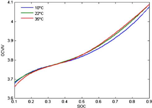
Is not possible to calculate max SOC based on max charge voltage as it depends on to many factors and is not linear but below there is a simple example showing around 75% if charged at 4V probably charged with CC and CV and the charge rate is unknown
But if only charged with CC at say around 0.25C to 4V should be around 70% of max possible charge thus 70% of real battery capacity can be used.
Going to 4.1V will allow for more likely around 80% of battery capacity using just CC charging at around 0.25C charge rate.
The only way to know for sure is to charge to full then reset the energy counters and make a full discharge as that will show the usable capacity.
You can see the PV current if you install the PV current shunt (not sure if you have that installed or not and if connected to anything) there is no need to use the DSSR20 you can still use the PV current shunt to provide way more data if you have other charge sources not just the grid charging.
There should not be any current trough the current shunts when you power up the SBMS0's as during power up the SBMS0's will read the voltage on the current shunt and consider that to be zero Amp's so if there is some current trough the shunts then this calibration will be false.
Since you have two battery in parallel (not something I ever recommend) then shunts should be connected to battery + but disconnected on the other end where batteries get parallel as is very likely there will be a small current flow from one battery to another and that will just mess up the zero offset calibration.
Say there is 1A flowing from one battery to another then one SBMS0 should show +1A meaning 1A is flowing in to battery and the other should show -1A meaning 1A getting out of the battery. But in this example if you power the SBMS0's and there is this 1A flow they will cancel this and consider this as the 0A state as that is the zero offset calibration and it expect's at power ON there will be zero current trough the shunt's
So now one SBMS will read 1A more than real and one will read 1A less than real this will create a fair amount of error in calculating the SOC that is done based on the amount of energy in and out of the batteries.
Rob Duncan
Mar 15, 2020, 4:53:48 PM3/15/20
to electrodacus
I sent you design schematics long ago as I began this project. I followed your suggestion on wiring the two batteries including the PV shunt which is connected in parallel to both SBMS0. Is this a problem?
Dacian Todea
Mar 15, 2020, 5:17:33 PM3/15/20
to electr...@googlegroups.com
Rob,
I remember seeing this but I can not associate that with names as I receive at least 30 to 50 emails each day plus a few forum questions.
You can just remove that copper bar between the two shunts in the photo then you can power ON the two SBMS0 then connect that shunt back ON that way should be zero current between batteries and zero offset calibration be correct.
Alternatively if is easier for you to do is to take the sense wires the Blue/White and Brown/White wires ad move them where you have the Blue and respectively Brown basically measuring zero volt no matther if there is or not any current trough those shunts then after the SBMS0's power up connect them correctly.
The important idea is that there should be zero current trough the shunts when SBMS0 powers up the way you do that is less relevant and this is more difficult when you have two parallel batteries.
But more important than correct SOC calculation is that all charge sources should stop when any of the SBMS0 say so and that is not the case for you based on the previous photo you sent where there was still a +8A charge current even if both SBMS0 asked for charging to be stopped.
For your particular case with two parallel batteries the way you test the EXT IO3 and IO4 is by having each individually set to type 0 while the other SBMS0 is on type 1 or 2 to test that each SBMS0 has the ability to turn OFF the charger and Load.
Rob Duncan
Mar 15, 2020, 6:34:13 PM3/15/20
to electrodacus
Dacian,
I am very impressed that you can keep all of us "mostly" in your mind at all, much less your wonderful online customer service. That's why I refreshed your memory with old images of my setup.
Although removing the bus bar is not too difficult, a temporary wiring of the the shunt sense wires together (BN to BN/WT, BU to BU/WT), do a SBMS0 power up, then reconnecting the shunt sensing wires back to their original positions. That may be tiresome if I am re-powering often. But I think things are coming together nicely for now. So may for the "last" time.
I already tested the existing series connection doing just as you suggest, setting one SBMS0 IOx to"0", then the other, ensuring it switches off. This was when I was using the Multiplus Assistant set to "Stop when Full" setting.
The most recent image you saw, showing 8 Amp charge thru each when both SBMS0 are at "Battery Full", is a result of setting Multiplus Assistant to "Float when Full". This allows some final filling to the lagging SOC battery, and was suggested by Geriak. Since the Float value is set at 24.35 V, this should divide up as 4.06 volts per cell. Safe enough as long as all cells are well balanced?
Another possibility would be to wire both EX IO4 ports in parallel. This would mean that both SBMS0 units would need to call for "Battery Full" in order for the combined IO4 circuit to open (Battery Full) and halt any further charging. This also implies that one battery could become slightly overcharged. I also don't think this is a safety issue given the conservative charge rate.
Short of adding another set of AC/PV chargers for second battery, I think this is the best I can do.
Dacian Todea
Mar 15, 2020, 6:58:36 PM3/15/20
to electrodacus
Rob,
Also parallel EXT IO4 is a bad idea and when any cell is considered full from any of the batteries the charging should just stop.
After you are done playing with all settings you should not need to power cycle the SBMS for probably years. Last time I power cycled my main SBMS (the SBMS120 powering my house) was somewhere last year and that just because I wanted to update the firmware (not that was anything new or necessary but to make sure there are no issues with the new version).
Since your type of cells have a fairly good relation between voltage and SOC (compared to LiFePO4) they can not be drifting to far apart as they are in parallel and if there is cell imbalance higher than 10mV that will be sorted by the cell balancing.
It is healthier for cells to be cycled even around the top than it is to do float (by significant margins).
Also you may benefit from setting the SOC limit to 90% in the DMPPT settings so that after a full charge to 100% in a day the battery will need to drop below 87% to start charging again and stop at 90% or even lower if you can afford. This will ensure the longest possible battery life.
Rob Duncan
Mar 15, 2020, 9:00:26 PM3/15/20
to electrodacus
Ok Dacian.
I have reverted to "Stop Charging" when "Battery Full" and with the SBMS0 ports in series. Charging stopped. Removed shore power, and left some interior LED lights on for a low drain overnight test, along with the DC powered refrigerator. The inverter is running engine battery trickle charger and the microwave phantom (idle) power. This is about 4.1 amps total according to the Victron battery monitor. One of the SBMS0 shows about 1.8 A load, while the other shows 2.05 A. Both batteries at 99% and 24.38 V. I assume the amps don't add up due to inaccuracies? I will check again in the morning and see if any imbalance has occurred. Then will turn on shore power assuming SOC has decreased below 96%. Charger should then run, right?
I may later try your suggested reduced DMPPT Max SOC to 90%, but with a mitigating increase in the other parameters like Over Voltage to 4.15 or so? This should do a stronger initial charge, then lower throughout the day. Cycled more towards the top of SOC. What do you think?
Dacian Todea
Mar 15, 2020, 10:04:19 PM3/15/20
to electrodacus
There is no need to go above the 4.1V that you already set.
Rob Duncan
Mar 16, 2020, 11:50:20 AM3/16/20
to electrodacus
This morning's test had same results as yesterday's. Running minimal "parasitic" overnight load per previous post. This morning found one battery at 83% and the other at 84%. Applied shore power which began 40 amp bulk charge. In less than one minute, one battery was at 99% while the other was still at 83%. Of course the SBMS0 IO4 commanded a charging shut down which occurred as expected. Screen images attached.
Dacian, Can you explain why this occurred? You can see the cell and overall voltages are not very different, yet now shows a 16% difference in the SOC. How is this calculated?
I did not do the shunt balancing trick that you suggested as it seems that is a "fine adjustment" whereas we have a major SOC difference that i can not understand.
Dacian Todea
Mar 16, 2020, 2:41:48 PM3/16/20
to electrodacus
I wish there was a photo during charging at 40A.
I guess you charged the batteries in a different way when you got them to 100%
Also if your settings are 4.1V as seen earlier it seems the internal resistance of the battery is very high that one of the cells got to 4.1V then dropped immediately to 3.929V
40A will mean just 20A on each battery and say each battery is 160Ah usable that is just nothing in therms of charge rate. It may be that you have one of the cell sense wires not properly connected (not where it needs to be connected like maybe the negative or the positive sense wire).
Seeing a short video of 10 seconds while charging was in progress will have given me more info.
I see battery is relatively cold and that will have some influence on the internal resistance of the battery but almost 200mV is way to high there must be something else related to connections.
Batteries are equally charged and probably around 83% if we consider your manual charge as 100% (not fair to do that). But I will like to know how connections are done to cell balancing my guess is that is not properly done and seeing what cell got first to 4.1V may give me a clue. If it was cell 1 then maybe your cell monitoring wires 1 and 2 are not directly connected to the cell 1 negative terminal but maybe to some other point and they measure the voltage drop on that wire adding that to the cell voltage resulting in inaccurate measurement.
DC Internal resistance of one of those 18650 should be around 50mOhm maybe 60mOhm as battery seems fairly cold so since there are about 74 of this in parallel that will be around 0.8mOhm but say is worse round that to 1mOhm
Then at around 20A charge current trough each battery that will be 20mV increase in voltage when connecting the charger very far from almost 200mV it seems to be in your example so at least one of the cells is not measured directly at the cells terminals.
Rob Duncan
Mar 16, 2020, 3:07:33 PM3/16/20
to electrodacus
Coincidentally the charger kicked on a couple minutes before you sent this. It charged for about a minute and then turned off with one cell at 100% and the other at 82%. I took a brief change to "Float with Battery Full", charging began again, and I received your mail. I pulled the shore power and "Charging Off" image is what is shown. Rather than waiting for another discharge, I simply plugged in shore power and the ~40 A Float charging is seen as "Charging On" image.
If you want me to discharge the system again, and reset to "Off when Full" - or whatever, I can do that.
I am quite confident in my balance cable connections, nor do I see anything that suggests an issue. You =don't see much cell difference in the two attached images. Recall my previously posted comment about erratic voltage readings during charge. I made a video, but don't know a way to upload for your viewing. It may be possible that one cell made instantaneous reading of 4.1 V which caused shut down, but that does not explain the 100% SOC reading then displayed after shut down.
I am working on installing the fluid heating system right now.
Dacian Todea
Mar 16, 2020, 3:24:19 PM3/16/20
to electrodacus
What are your parameters ? The same as you sent earlier with EOC 4.08 and OverVoltage set at 4.1V ? Because if that is the case I do not see why the charging terminated so fast just one minute since as it looks now it will take at least half an hour before it will get to 4.08V to terminate the charging. Charging seems to be done at least at around 50A
So not sure how the charging has terminated first time you charged as based on that photo and your old parameters that should not have happened. Maybe you have the default 4V parameters in the ISL94203 as maybe you changed to new parameters and did not power cycled the SBMS0 after you did that. As any changes made in Parameter settings will only take effect after a power cycle.
Dacian Todea
Mar 16, 2020, 3:32:45 PM3/16/20
to electrodacus
I watched the youtube video and there is nothing wrong with that. What was the charge source there ? and was there any load ? There was very small fluctuation like it is the case when charging with a switch mode charger but nothing problematic (absolute normal).
Rob Duncan
Mar 16, 2020, 3:34:43 PM3/16/20
to electrodacus
Charging from same Multiplus as always.
Dacian Todea
Mar 16, 2020, 3:40:47 PM3/16/20
to electrodacus
Yes as I expected. Charging that way will be much noisier than charging from solar is similar to using the inverter as is just the inverter used in reverse.
Rob Duncan
Mar 16, 2020, 5:32:52 PM3/16/20
to electrodacus
OK. So what next?
Just for my reference, does the IO4 go "open" when the 4.1 OV is achieved, or when the 4.08 EOC is achieved? Or Either?
Is there any way to determine if SOC or some other value(s) triggered the event? That might help debug.
Does it happen with an instantaneous value, or is some hysteresis or averaging done? i.e. six hits on same cell value within x seconds to trigger "Battery Full".
I suppose I could remove the SBMS0 IO port series connections, just use one, and trust that the batteries are tracking together "safely enough" such that when one SBMS0 commands a "Stop Charging" that the other battery/SBMS0 is close enough to be safe? This could also be effectively done by placing the SBMS0 connections in parallel such that both need to be at "Stop Charging" for it to happen.
Thoughts?
Dacian Todea
Mar 16, 2020, 6:38:50 PM3/16/20
to electrodacus
First time in a day the SOC will be reset at 100% when EOC is reached and charging will stop soon after when it gets to OV all subsequent charge cycles will start when SOC is below 96% (as soon as it drops to 95%) then will charge until it gets to 99% or EOC whatever comes first.
Yes you can see the OV flag set if that was the cause that triggered the charge to stop and if that is not then it is based on SOC.
Looking at photos it seems the second SBMS0 has not had the time and date set also WiFi is OFF on the second one. (Since you have two SBMS0 you need to change his name to SBMS1 in WiFi menu and select a different channel in order for WiFi's to work) but not relevant to the problem.
The time and date is important as if they are not set you do not know when the new day will be set it will be different if one of the SBMS has not set the time and date so one will think a new day started at a different time maybe even during the day depending on when you reset the SBMS0 as if you do not set the time it will start from 0:00 at the moment you connect.
You should use the EXT IOx from both SBMS in series so that wen any of the SBMS0 battery is full charging stop and they should be very close.
The problem is you charge the battery forced ignoring this EXT IOx so it will be more than what SBMS normally considers 100% SOC then one of them will charge first and set to 100% while the other remains at less that that.
If batteries will start from same charge state 100% then discharge to some value say 70 or 80% and then charge back I will not expect to see any more than 1 to 3% SOC difference between them but in your case I seen one showing 99% fully charged and the other I think 83% and the difference is way to large that means you charged manually way above 100% say 115% then discharged both of them and then charged correctly with EXT IOx controlling the charging so the battery that got first to what SBMS0 considers 100% was reset to that level while the other was not.
You could then just manually charge a bit extra just enough that the second battery will also reset to 100% probably 30 seconds to one minute more and then just stop and leave at that level both correctly showing the 100% based on the set limits then next day after a 20 to 30% DOD when they came back there will still be one battery that will be first charged and reset to 100% but then the second one will be at 98 or 99% so not far from the other one.
There is no way around this as one of the batteries will always charge first even if it is by just a few seconds.
Also another problem is that you change the charge rate as the charger gets to absorption charging when charge current drops and this should not happen. You should change the absorption voltage to something higher than battery voltage so it never gets there say 25V or more then it will always charge at 50A (about 25A on each battery) until charging terminates and there is no lower charging current to get consistent results.
Batteries are fairly close in SOC so you should just connect the EXT IO4 of both SBMS in series and control all charge sources with that. Then the highest SOC indication will be the correct one the other should be very close but less accurate.
This is one of the multiple drawback's of paralleling two batteries.
Rob Duncan
Mar 16, 2020, 7:10:27 PM3/16/20
to electrodacus
WiFi is the least of my worries at this point.
I have previously set date/time, and don't "think" I have done another power reset. I don't know how the clocks became unset. Must date time be reset with each power reset? Do I need to click "Save Parameters" after that? How do I "synchronize" the clocks? Is this necessary?
Both are quite full right now, 99%, and I just set to roll over a virtual "midnight" within five minutes. Is this what you are suggesting? It is not clear to me what steps should be taken. I hope this solves the imbalance problem.
Just a comment. Can you try shorter sentences? It takes me a lot of re-reading to get what you are saying much of the time. Multiple syllables are fine :^)
I don't think the charge current rate can be set on the Multiplus. Just the voltage for the Absorption and Float.
Dacian Todea
Mar 16, 2020, 7:19:53 PM3/16/20
to electrodacus
Yes date and time will not be saved at power cycle as there is no internal battery inside the SBMS0 to maintain the clock. You need to set the date and time every time you power ON the SBMS.
Charge current will stay to max 50A as long as absorption voltage is set higher than max possible battery voltage so above 25V in your case same for float.
If you do this set float and absorption high enough then there will only be bulk charge so charge current will always be that max 50A
Rob Duncan
Mar 16, 2020, 10:05:35 PM3/16/20
to electrodacus
Understood, but doesn't the Multiplus settings control it's own charge rate? How would the SBMS0 control charge rate?
I will try again tomorrow morning and hope the date time reset fixes the SOC difference.
Dacian Todea
Mar 16, 2020, 10:14:26 PM3/16/20
to electrodacus
The Multiplus will charge at full current until it gets to set absorption voltage and since that will never happen if set correctly higher than max battery voltage the SBMS0 will stop the charging before the Multiplus can get to Absorption stage that is the constant voltage stage where it tries to maintain that voltage and slowly reduce the current.

Barry Timm
Mar 17, 2020, 12:04:35 AM3/17/20
to electrodacus
Rob, putting what I think Dacian is saying a different way.....
Yes, if you installed the Multiplus in a non Lithium battery system, you would use the Multiplus charger protocols to set the max bulk charge rate (if necessary for your battery size), the Absorb voltage limit and the float voltage limit. The Multplus charger would then go through the normal Bulk, Absorb and into Float cycles.
But in Dacian's SBSMxx systems, because they are built for Lithium technology batteries and NOT for lead-acid systems, and because Lithium is best charged with a specific current until a cell level maximum voltage threshold is reached, after which all charging must stop, there is NO Absorb or Float charging at all. One simply charges the Lithiums at the recommended current until the SBMSxx predefined voltage threshold is reached, and then the charger must be switched off.
In order to do this, it's important to note that the maximum voltage is at the cell level - thus as soon as the HIGHEST voltage cell reaches the voltage threshold, the SBMSxx must switch off the charger entirely.
In order to force the SBMSxx to control the charging, in order to prevent the Multiplus from reaching its ABsorb voltage or float voltage threshols and switch from Bulk to ABsorb or to Float, you should set the Multiplus Absorb and FLoat vltages ABOVE the maximum voltage threshold in the SBMSxx. This will then let the SBMSxx take over control of the Multiplus withut the Multiplus managing and invoking the unwanted Absorb or Float cycles.
In summary, the Multiplus charger is used for BULK charging only - never entering into Absorb or Float phases. Same with any Solar Charge Controller....you always want the Charge controllers to stay in Bulk charge until the SBMSxxx decides to stop the charging.
In my mind, this is why the much cheaper, simpler, DSSR20s are the natural solar controller modules for the SBMSxx system, instead of using a 3rd party SCC or battery charger that is used for only Bulk charging.
Dacian will hopefully correct any misinformation in the above....but that's the way I understand how these devices are used in his system.
Rob Duncan
Mar 17, 2020, 12:12:55 PM3/17/20
to electrodacus
Thank you Barry, for paraphrasing Damian's explanation. It now makes perfect sense.
A little back-story - I know my installation is the "lame duck" in this groups of off-grid homeowners! I began my RV upgrade replacing the 100W Zamp solar panel with 4 x 200W 12V panels, and planned a simple "bigger FLA battery". Soon after watching a few YouTube conversions using Tesla batteries, I decided go to a 24 V bus system so that I could have that option. Thus I installed the all Victron 24V support system. Then Geriak introduced me to the Electrodacus. Since his RV is identical to mine, I followed his lead in many aspects.
Thus I have over-spent for the project due to changing goals. However, this path does give me, or some future owner, the ability to change battery type, etc. and keep resale value of known high grade electronics. I did become very disenchanted with Victron. I expected a more homogeneous solution by using a single vendor, rather than price-shopping. Their multitude of buses and interfaces amaze me, all coming from a single vendor. A virtual house of cards. Then add an SBMS0!
That said, perhaps the Electrodacus manuals can be revised to explain and show how Victron and other standard chargers should be programmed to make best use of Lithium batteries. On the other hand, perhaps Victron should make similar documentation and programming changes!
This brings up the question, does the BattleBorn or other popular Lithium batteries with built-in BMS work in the same manner, i.e. would require a Multiplus to b programmed with higher Absorption and Float voltages, and thus rely upon signaling back to the Multiplus to stop Bulk charging?
Since I have re-zeroed the SOC last night, I am about to try another test of depleting the batteries, then recharge using the suggested "Bulk Only" Multiplus settings, and see whether SBMS0 halts charging with a close SOC value for each battery.
On a positive note, this unexpected and ongoing trouble shooting is certainly keeping me in self-quarantine mode! Not wandering the countryside. Stay healthy, everybody!
Rob Duncan
Mar 17, 2020, 12:36:39 PM3/17/20
to electrodacus
I just noticed this charger setup page.
Should The Enable Battery Monitor be "On"?
Should the SOC When Bulk Reached be set to "100%"?
Does the Absorption and Float setup look correct?
I am really hoping the battery imbalance is all a programming issue.
Rob Duncan
Mar 17, 2020, 1:24:07 PM3/17/20
to electrodacus
Dacian,
I performed the following test:
1. "Forcing" Float charge to achieve near 4.07 volt on all cells, thus 24.4 V on both batteries, SOC showed 99%
2. Set Multiplus Absorption and Float voltages to 24.5 V, max charge rate is 70 A
3. Verified "Stop when Full" set.
4. Set both clocks to 23:58, and waited five minutes for them to set day's max SOC at "midnight"
5. Removed shore power, ran the 50A heat pump for a few minute to reduce SOC to 93% and 95% respectively. Turned off pump.
6. Plugged in shore power.
7. Charger began in Bulk mode, ramped up to about 40 A, then shut down within 30 seconds of operation
8. Both battery's SOC now show 100%, but the voltage is much lower than full charge. Current pages attached.
What am I doing wrong, or is there a problem?
I appreciate your prompt response.
Dacian Todea
Mar 17, 2020, 7:05:40 PM3/17/20
to electrodacus
Rob,
1,2) Set absorption and float at 25.5V (high enough your battery will never get there) then charging will only be done at bulk levels.
5) How long did the pump run at 50A to drain the SOC to 93 and 95% and what was the initial SOC you started with also how was that charge done (manually forcing charge) ?
7) 30 seconds seems way to low unless the battery was not charged in this same way but forced charged manually.
8) This is the correct 100% do not manually charge to more now you can repeat the test with discharging at 50A and charging at 40A and will work much more correctly.
Rob Duncan
Mar 17, 2020, 8:33:51 PM3/17/20
to electrodacus
1,2 - I don't like the idea of setting voltage higher than the battery max spec of 25.2V. Especially since I am using a conservative 4.1V (24.6) Max cell voltage. Unless you object, I will set Absorption and Float to 25 V (4.16V max cell).
5 - I don't recall the exact time pump ran. I will time and note the current draw next time as I know current draw through the inverter will be based upon battery voltage at the time.
7 - I agree the time was too short. I used the Float charging which brought all cells to about 4.08V (24.48V). At this level, which should be a true 100% of my programmed max, I did the "reset to midnight".
8 - Not how can be the "correct 100%" with such low cell voltages (~3.97V). I have reduced charger to 40A.
Attached images show
18020 - Start of test
18114 - Begin discharge at ~50A
18135 - End of discharge
18114 - Start of charge
18195 - End of charge
You can use 1800 = 6 pm, and determine elapsed time.
Ending is 4% SOC difference, and the cells are no where near the 4.1V expected value.
Not balanced, not full.
Dacian Todea
Mar 17, 2020, 8:58:49 PM3/17/20
to electrodacus
Rob,
1,2) Unless you play with manually bypassing the EXT IOx on SBMS there will not be a problem with any cell exceeding the 4.1V you set. 25V should also be fine depending on how accurate is that measured by the Victron.
5) You can just simply look on the SBMS0 graph's page 5 of the monitoring and you will know for how long a load run or how long the charging was running for.
8) It seems you discharge at around 92A split between the two batteries
For some reason the SOC jumped to 99% likely reset by one cell getting to 4.08V but not sure how that was possible as it looked all cells were well below 4V during charging so not sure what happened there.
Have you checked the Advanced parameter settings on that first SBMS0 are correctly set at 4.08V for EOC? Since this was not the first charge of the day it stopped the charging as SOC jumped to 99% due to EOC threshold being set for a few seconds (I think 3 seconds tho when you took the photo that was no longer set).
Rob Duncan
Mar 17, 2020, 9:39:49 PM3/17/20
to electrodacus
Dacian,
1,2 - I have not done anything not reported here. Nor manually bypass anything. The Advanced parameters, etc. are just as originally set and imaged on this thread. The Victron has voltage sense wiring implemented, so it should be quite accurate, solid, and not be affected by any voltage drops during charging. Since we are in bulk mode, the voltage may not be used.
5 - The date/time stamp of the image files can also be used, and provides more resolution. There may be more details with the maps, but I have not learned how to use them.
8 - Image 180202 shows pump discharge start at 66 amps. 18114 (~9 minutes later) shows 92A as the battery voltage has decreased, and the current increased just as expected. SOC are still identical during discharge. They were within 1% while charging until the end where one jumped to 100.% Although jittery, no cell ever was seen above 3.9V.
I tried to take the photo immediately when the charger shut down. This is the best I can provide.
Dacian Todea
Mar 17, 2020, 10:25:09 PM3/17/20
to electrodacus
SOC will not jump to 100% unless EOC flag is set and it will not be set unless one of the cells get's to set limit (I assume that is 4.08V) and not the default 3.98V
Rob Duncan
Mar 17, 2020, 10:42:43 PM3/17/20
to electrodacus
Dacian,
I hear you. Here are images of the current parameters. Still 4.08V for EOC. As you can see, I have changed nothing, nor have any reason to deceive you. We just need to find out what is happening. Are you sure an instantaneous voltage reading might not trigger EOC and we are fighting a noise problem? If so, perhaps capacitors on the voltage sense leads could filter this? Or a s/w modification?
What next?
Dacian Todea
Mar 17, 2020, 11:16:00 PM3/17/20
to electrodacus
Of course an instantaneous voltage reading will set the EOC flag but from the video you uploaded I have not seen such large voltage jumps and that EOC will need to persist for more than 3 seconds for the SOC to reset so it can not be just one second.
I could change the software to require both EOC and OV flags in order to reset the SOC but in my tests that was not necessary.
What you see in Parameter setting is what is stored in the EEPROM memory so if you set those and saved it will show as those values but if you did not power cycled the SBMS0 since you saved those settings they will not be in the RAM memory that is what the SBMS0 uses to work with.
So me seeing that 4.08V there is no confirmation that those are the current used parameters since to know that I will need to know that you power cycled the SBMS0 after you saved those parameters.
In the earlier photos you sent the charging was terminated by the SBMS on the right when the OV was set that is 4.1V for at least one second and the end voltage when you made the photo was 3.98V about 100mV lower but possible since it may have been some seconds after charging has ended and there was some small probably 1A load on each battery.
The next software version that I will release I will add an option to disable this limit to full charge just once a day tho I will still recommend using that. Typical charging is done with solar that is much cleaner and solar will have some times lower charge rates depending on the time of day and whether.
Your batteries are not perfectly equal so there will always be a battery that will finalize charging first but they will not be able to drift far from each-other as they are paralleled so voltage will equalize.
Rob Duncan
Mar 18, 2020, 9:05:20 AM3/18/20
to electrodacus
I am quite sure both SBMS0 have been power cycled with that setting. Of course I can do this again if you desire. Other than that, what steps do you reccomend be done next?
Rob Duncan
Mar 18, 2020, 1:30:25 PM3/18/20
to electrodacus
Dacian,
Can this happen:
1. An instantaneous voltage reading at/above 4.08V (EOC). I assume you save the system clock time.
2. Many other readings, below EOC occur. Those system clock times are not being saved as they are not relevant to the EOC timeout.
3. Another reading at/above EOC within 3 seconds from Item 1. I assume 3 seconds is your internal EOC check timeout?
4. The SBMS0 "Battery Full" condition is thus met, and EOC flag set, EXIO4 goes open, and SOC is set to 100%
If the above scenario is possible, then I believe that some higher voltage variations are happening so fast that our eyes and video can not capture them.
A simple digital filter could be done with a "rolling average" over a three (or more) second period. i.e. The "average" cell voltage must exceed the EOC voltage setting before going to Step 4 above. This would make the SBMS0 system more robust, and fault tolerant for noisy charging systems.
Dacian Todea
Mar 18, 2020, 2:03:31 PM3/18/20
to electrodacus
It needs to be 3 consecutive seconds.
And the EOC flag is set by the ISL94203 not the microcontroller. The microcontroller just monitors that flag and if the flag is set for 3 consecutive seconds the SOC is reset to 100% but charging will not stop until also the OV flag is set that is usually 20mV higher and require one second consecutive above 4.1V that you set (the 1 second can be increased in advanced parameter settings but should not be needed). This is what happens at first charge of the day and subsequent charges will stop when SOC gets to 99% will no longer wait for OV to be set.
The refresh rate on the monitoring screen is at least 4 to 5 readings per second it is not likely you will not be able to capture in video when voltage exceed 4.08V.
So the first charge each day (assuming time is set correctly the reset for a new day will happen at 0:00) will be a full charge stopping when OV flag is set. The subsequent charges are less relevant but it is annoying that SOC is reset much sooner than expected (is this always happens on the same first SBMS0 ?)
I do not get this behavior with my 100Ah LiFePO4 testing battery but I do charge with solar PV only so cleaner charge current.
Rob Duncan
Mar 18, 2020, 3:23:18 PM3/18/20
to electrodacus
Although you think clear to you, I am not sure how you determine "3 consecutive seconds". I suppose I could review the ISL94203 datasheet for better understanding.
Does those flags get set in the ISL94203 whenever an instantaneous EOC or OV voltage is seen? What clears them? Will a subsequent lower voltage reading clear either flag?
I am still concerned that the noisy Victron is root cause of the issue. Its effect may be aggravated somehow with my physical installation, cable lengths, cross-talk, etc. I hope that being among the "bleeding edge" of your customer base, we can resolve this together. Consider me your remote testing facility.
Do you want me to try increasing the OV timeout parameter? Not knowing what clears the flag makes this a shot in the dark, but willing to try.
I just:
1. Disconnected (+) to charger
2. Disconnected battery (-) so all shunts would be zero.
3. Did power on reset for both SBMS0. SOC shows 49% and all cells were about 3.8V at start.
4. Reset clocks to current time of day.
5. Reconnected battery (-) to bus
6. Reconnected charger to (+). Did a power reset.
7. Charger ran at about 30A for about 5 minutes. Voltages rose slowly and all remained "close" while slowly rising
8. Just before charger stop the SOC was 50% on both units
9. Charger stop. Right SOC jumped to 100% Left remained at 50%. Voltages and flags seen in attached images. None are anywhere near 4.08V so neither battery is fully charged. This is a fundamental problem. Premature EOC.
Dacian Todea
Mar 18, 2020, 3:57:53 PM3/18/20
to electr...@googlegroups.com
Rob,
2. Not correct the batteries are in parallel and there will be some current flow between the two batteries thus current shunts will not be zero.
3. Correct the SOC is set at 50% at initial power ON as SBMS has no idea about the real SOC
7. Was that 30A on each battery (60A total) if so that will be around 3Ah in minutes and that should be about 2% SOC if each battery is set at 160Ah but I guess it was 30A split between the two batteries then it was just under 1% SOC charging thus still at 50% was close to switching to 51%
9. Something looks wrong as since this was the first charge of the day the charging will have stopped at 4.1V for more than one second and the OV should have been ON. The 200mV between 3.9V current and 4.1V seems way to high. and I did not seen anything close to that in your video.
You should just perform this 9 steps again and take a video for me to see what is going on as the 200mV seems way to high. And as mentioned the SOC will reset based on EOC will not be the cause of charging being stopped when this was the first charge in the day and OV was needed to also be set for the charging to stop.
You can before resetting modify the over-voltage delay to 3 or 5 seconds on both SBMS0 and save parameters then you can do the power cycle and take the video as based on what you say it will not take more than 30 seconds to one minute before will be full again.
Rob Duncan
Mar 18, 2020, 6:42:21 PM3/18/20
to electrodacus
2. Good point! Can this be causing the premature stop charge issue?
9. How long of a video do you want? From step one thru 9?
10 (new). I increased the OV Delay from 1 to 5 seconds and decreasing the OV Recovery from 3.95 to 3.90V on the right SBMS only as that seems to be the one that always halts the charging. Power Reset both devices. The charger ran for about one minute and was stopped by the right side. OV flag is not on. So why was charging being stopped?
Images show state after charging stopped. Left SBMS parameters remain unchanged from very start.
Dacian Todea
Mar 18, 2020, 8:04:01 PM3/18/20
to electrodacus
2. Will just calculate slightly wrong the SOC if not calibrated correctly but has nothing to do with your charge problem.
9. I need just 10 to 15 seconds before the charging turns OFF to see what was the reason.
10. Was the power reset done ? as if so the left SBMS0 could not have gotten to 51% in one minute of charging only. Also I do not see the OV flag set on the second SBMS0 meaning this was not the fist charge since reset else charging will not have stopped until one cell voltage was at 4.1V for over 5 seconds.
It just looks like SOC was reset by the EOC threshold and then 3 seconds later it stopped charging as the SOC was at 99%
Not sure if I can paste code here but this is the relevant part
this first one is the rule for EXT IO4 set as type 1 and ON means close circuit charging enabled and OFF means open circuit so charger OFF
CFETerror refer's to CFET flag if is OFF for more than 3 second then charging will be OFF
sbms0charge refers to SOC limit so in your case is 99% thus more than 0 so charger will be ON unless is not a new day (not first time charging is done) see second part of the code for when this variable can become zero and turn off the charging.
sbms0dualPV is less relevant for you as you do not use dual PV array so none of your EXT IOx are set as type 6 thus it will level will always be L1
if (CFET==0){CFETerror++;}
else {CFETerror=0;}
if (DFET==0){DFETerror++;}
else {DFETerror=0;}
if (CFETerror>=3){CFETerror=3;}
if (DFETerror>=3){DFETerror=3;}
if (EXT[2]==1){if (CFETerror<=1 && sbms0charge>0 && (sbms0dualPV==1||sbms0dualPV==3)) {EXT4_ON;} else {EXT4_OFF;}}
Then this is the second part:
and as you can see if sbms0newday is 1 meaning this is first charge of the day then sbsm0charge will always be higher than zero on your case 99 (the default 99% charge limit) and charging should terminate when CFET flag is turned off and this happen at over voltage.
#if SBMSmodel==0
if (sbms0newday==1) {hsoc[9]=3;sbms0charge=DMPPTval1[0];} //max current when using type 6.
else
{
if (DMPPTval1[1]>=SOC1+hsoc[9]) {sbms0charge=DMPPTval1[0]; hsoc[9]=0;}
else {sbms0charge=0; hsoc[9]=3;scandelay=5;}
}
if (sbms0charge!=0 && scandelay==0 && CFETerror==0 && (EXT[0]==6||EXT[2]==6||EXT[4]==6||EXT[6]==6))
{
// if (sbms0dualPV==0){sbms0dualPV=1;scandelay=5;}
if (sbms0dualPV==1){if (sbms0charge>((PV1+1)/500)) {sbms0dualPV=2;scandelay=2;} }
else if (sbms0dualPV==2){if (sbms0charge>((PV1+1)/660)) {sbms0dualPV=3;scandelay=2;} if (sbms0charge<((PV1+1)/1200)){sbms0dualPV=1;scandelay=2;}}
else if (sbms0dualPV==3){if (sbms0charge<((PV1+1)/1200)){sbms0dualPV=2;scandelay=2;} }
}
if (CFETerror!=0 || sbms0charge==0 || (EXT[0]!=6 && EXT[2]!=6 && EXT[4]!=6 && EXT[6]!=6)) {sbms0dualPV=1;scandelay=3;}
if (scandelay>0){scandelay--;}
#endif
Rob Duncan
Mar 18, 2020, 8:58:19 PM3/18/20
to electrodacus
2. OK. So I will not worry about this until charging issue is resolved. It seems like the single (-) disconnect switch I proposed a short while ago should be discarded and separate battery (+) switches installed. This is a bit problematic due to current circuit layout and available space.
9. I will do this tomorrow morning. I don't have any video editing software, so "last 15 seconds" may be hard to achieve. What SBMS0 pages do you need to see?
10. Yes. See my Step 10 in my 4:42 PM post. It also states that only the the RIGHT SBMS settings were modified as seen in images. Note the LEFT still has the original values, and Power reset was done.
I have many unanswered previous questions, such as how/when OV and EOC flags get reset, where is CFET set/kept, etc. I don't recognize these conditions in your code yet.
Too late in my day to read your code, but I really do appreciate your providing it! I am sure I will have questions. The main issue may be in the ISL94203 as previously pointed out. Step ONE must be to determine WHAT condition is causing "Battery Full" (what code flag is that?). Then we can try to address the issue.
Rob Duncan
Mar 18, 2020, 8:59:31 PM3/18/20
to electrodacus
Sorry.
Also on 9. (Video) What steps do you want taken for the test setup?
Dacian Todea
Mar 18, 2020, 9:18:16 PM3/18/20
to electrodacus
9. It is important to see that last few seconds when charging stops in first page of the monitoring and if video is longer is no problem for me.
10. The OV flag and EOC get reset by the ISL94203 you can check the spec for details but OV will be reset when highest cell voltage drops below the overvoltage recovery in your case 3.9V and while I can not see the voltage for that one in the right I assume it is possible all cells where below 3.9V thus the OV could have been reset but there is a problem with your setup if a cell was able to get to 4.1V for 5 consecutive seconds and then dropped below 3.9V and I have not seen anything close to that in your last video that is why I'm very curious to see what is going on. It is more likely that only the EOC was reached maybe for a brief second and that was the reason charging stopped but that means this was not the first charging of the day as that is the important one. Is less important where charging stops on subsequent charges during the day as battery will like to stay more than fully charge during the day.
The CFET is also turn ON or off automatically by the ISL94203 so it is done in hardware not software based on the other flags. So if OV flag is turn on the CFET flag will automatically be turned OFF.
So the SBMS0 software looks at the CFET flag and if that is off then EXT IOx set as type 1 will also turn OFF no matther what other settings or flags are.
It is important that the charge you monitor is first charge of the day that can be done by either power cycle the SBMS0 or simply by setting the time to 23:59 and wait for about two minutes then charging will be enabled and that first charge should terminate only when OV flag was set and that will only be set if voltage is above 4.1V for 5 seconds consecutive based on your last setting on the right side SBMS0.
Rob Duncan
Mar 19, 2020, 2:13:19 PM3/19/20
to electrodacus
It took a couple hours to figure out video editing to keep form waiting for a two hour YouTube upload, but here is test results.
You did not provide any further testing guidance on what to watch, so here it is.
1, Rebooted both SBMS0, set clocks to 23:58 and waited for past midnight.
2. Restarted charger
3. This time the left SBMS triggered first.
Video is seen at YouTube "End of first charge".
images
20200319
_0956 - showing clock past midnight - is there a better page to see this?
_0957 - starting values after SBMS0 reboot
_1157 - advance parameters after test.
Dacian Todea
Mar 19, 2020, 4:04:03 PM3/19/20
to electr...@googlegroups.com
Yes I see in the video what it going on. The EOC seems to terminate the charging I will change this in new firmware to the over-voltage that will terminate the charging.
You seems to have very long lines for cell balancing and so very large voltage drop during cell balancing and that is what sets the end of charge so prematurely.
You can maybe increase the thickness for the cell balancing wires to reduce the voltage drop you can also increase the EOC voltage to same level 4.1V as overvoltage tho that is o very little help the cell balancing drop should be reduced then you will get much closer to a full charge. Even when I change the firmware such large voltage due to cell balancing voltage drop on wires will may get to overvoltage lock I think that is set to 4.2 or 4.25V so not that far so this cell balancing wires need to be improved.
I have not noticed this problem with the LiFePO4 that I test on as there I have the EOC set at 3.53 and OV at 3.55V and withing those 3 seconds the voltage gets past 3.55V and so OV is set.
This is not a problem for most as they do not have this large cell balancing drop so charging is much closer to set limits even if the charge is stopped by EOC flag.
Looking again at the video it may also be the way the connections are done cell 6 that triggered the EOC and on both sides the cells 3 and 7 where doing cell balancing so both voltage drops added to that cell 6.
Do you have a ST-Link programmer to flash the new firmware when available ?
I will try to look this weekend at the code and see if not using EOC as termination of charging is a better idea. I may have had a reason to do that that I do not remember now so will need to check all the code.
I will leave the SOC reset at EOC and only move the charging termination to over voltage.
Thanks for the video I was sure I implemented charging up to OV limit at first charge.
Rob Duncan
Mar 19, 2020, 5:17:05 PM3/19/20
to electrodacus
At about 1:24 into the video, I do see cell #6 peak at 4.068V for just an instant. This is 236mV above the lowest cell #7 at 3.831V. Is this voltage difference the "balancing voltage drop" you refer to?
Still this not the 4.08V EOC setting, and by 1:26 #6 has dropped to 3.948V. Is just one instant all that it takes to trigger EOC?
I am already using a 12 conductor, #22 AWG round cable from the battery to the SMB0 as seen in previous image I sent. This is much thicker than the supplied ribbon cable. There is an additional Molex connector. Total cable length is 14 ft including about 4 ft extra length "service loop" to facilitate plugging cable into the Tesla battery prior to the battery being inserted into the battery box. The battery box is quite tight, but I "could" shorten by this amount and just do a lot more cussing whenever it next becomes time to remove the batteries :^)
Four ft of #22 AWG is about .064 ohms, one way. I am not sure if your supplied ribbon cable is 26 or 28 AWG, but I can't imagine the #22 AWG would have significant voltage drop. What is the anticipated current during balancing?
I don't understand what you mean here: "both sides the cells 3 and 7 where doing cell balancing so both voltage drops added to that cell 6."
I don't have, nor ever used, a ST Link programmer. If this what I need
... then I see no issue in buying one and learning its use. Let me know so I can order ASAP for quick delivery.
Isn't there a way you can set a longer delay such that the EOC voltage limit needs to be there for 10 (or ?) seconds? Or even require EOC on at least two different cells?
I honestly have not found time to review your code.
I still think making Electrodacus SBMS0 more robust and fault/noise tolerant is better for both of us. You may have fewer grumpy customers!
Meanwhile I will try adjusting the EOC setting to 4.1V (or more), and rerun the "First Charge of the day" test.
Barry Timm
Mar 19, 2020, 5:25:43 PM3/19/20
to electrodacus
Just an FYI that the Bogart solar charge controllers with which i have 3 years of experience use a rolling average over 22 seconds to determine voltage threshold limits being reached.
I do think that some kind of averaging is needed to avoid unintended peaks affecting the state switching.
Barry
Barry Timm
Mar 19, 2020, 5:25:59 PM3/19/20
to electrodacus
Rob Duncan
Mar 19, 2020, 5:41:37 PM3/19/20
to electrodacus
Dacian,
I don't want to shorten the balancing cable unless you think REALLY required.
Unless I physically remove the batteries to remove the balance cable connector at the battery, the chance of shorting the balance wires is very great. Even If I carefully remove the cable sheath and then separately cut each wire, those ends can very easily touch and short out. Stuff happens.
Removing the batteries requires hours of effort in close spaces, and removal of external thermal insulation. I am very close to completing the fluid heating system, and would likely complete that task while waiting for your input. After that, battery removal would also require draining fluid and removing plumbing from the batteries.
Dacian Todea
Mar 19, 2020, 5:50:10 PM3/19/20
to electrodacus
Rob,
Yes that is the voltage drop I talk about as cell 7 and 6 have a common wire and so is cell 6 and 3 so both of those voltage drop adds up as positive to cell 6 reading.
So is 18ft total of 22 AWG plus some contact resistance. It is a bit high but should work much better with new firmware that I just tested.
Since on the right and left of cell 6 you have cells 3 and 7 and each of this the 3 and 7 have cell balancing active there will be a voltage drop on both sense wires used by cell 6 and the way that voltage drop polarity is it will add up to what the cell 6V is in reality.
So say you have 22 AWG wire 18 ft that should have 16mOhm per ft assuming is really 22AWG and not rounded to that level from some metric value.
Total resistance 18ft x 16mOhm = 288mOhm = 0.288mOhm then multiplied with about 0.16A = 0.046V drop but likely there are a few contacts harder to say what resistance will all those have so this is time two as there is the other wire maybe about 100 to 150mV including contact resistance.
That 235mV is total delta between low cell 7 that is balanced and for that the voltage drop will subtract from real cell voltage as it reads 3.822V while it is in fact 3.912V about 90mV less and the cell 6 that is 3.958V in reality but reads 4.068V (at some point 4.08V to set the EOC)
around 110mV more than it should plus there is a cell delta anyway so this two plus existing cell delta gets you around 235mV
Yes that ST-Link is good on eBay is less but maybe more risk to get a bad one.
Already made the fix and will release the code soon after a bit more test this weekend. I also made a video need to edit to show how the new firmware works on my test system.
Barry,
Will soon post a video showing the proper fix not a good idea to have such a long average. I like to show on screen what the actual measurement is no need to remove the cell balancing variation as that is good for diagnostics like long cell balancing leads can be seen.
Dacian Todea
Mar 19, 2020, 7:14:39 PM3/19/20
to electrodacus
Here is the video with the new firmware https://lbry.tv/@electrodacus2:e/SBMS0-v40p:e
This is on an old GBS LiFePO4 battery charging with a single DSSR20 connected to two 260W panels
The SBMS was just power cycled as I wrote the new firmware and battery was already almost full.
With LiFePO4 is just maybe 1% SOC extra using the new firmware but for Rob it will be more significant due to different type of battery and a bit higher voltage drop on cell balancing wires.
The EOC is set already 5 seconds in to the video at 51% so after 1% SOC charging and then charging is now ending at 52% so after another about 1.5% SOC push in to battery around 5 minutes and 30 seconds in to the video.
Is a raw video so I uploaded on my lbry account as it was not proper for my main youtube channel.
Rob Duncan
Mar 19, 2020, 7:19:22 PM3/19/20
to electrodacus
Dacian,
As stated before, I have 14 ft of #22 which yields .224 ohms. The supplied 10 ft ribbon cable has either 26 or 28 AWG. Assuming 26 AWG (which I doubt) that yields 10 x .0408 = .408 ohms. Therefore my current cabling has about 1/2 the resistance of the supplied cable. This does not implicate my cabling as the culprit.
I ran a second test using 4.1V as EOC setting. Last minute is uploaded to YouTube as "Early Shut off - 4.1v expected". At :39 into the video, cell 2 max reached 4.057v - NOT the EOC 4.1v setting. Charging was disabled two seconds later.
I am not sure what software fix you made, but doesn't my test that 4.1 V setting (same as the OV value) prove that using OV instead will not fix this issue? The only difference as I understand it is that EOC is always used as the first charge limit of the day.
I am still not clear about how voltage drop factors in. If the highest cell voltage is 4.0V, and there is one cell at 3.9V and another at 3.8V, how does that impact the setting of EOC which is expected at 4.1V or whatever?
ST Link is on order.
Dacian Todea
Mar 19, 2020, 7:31:27 PM3/19/20
to electrodacus
I only supply 6f of cable and that is 28AWG for SBMS0 about 400mOhm and yes your cable is around 300mOhm so should be fine tho I do not know how much the connectors add to that and also the cable inductance influence on the readings.
In any case it is not that bad as mentioned and should work fine with new firmware see my video if you did not see my last post https://lbry.tv/@electrodacus2:e/SBMS0-v40p:e
The displayed values are averages of a few readings and so peak for a few ms was above 4.1V else the EOC will not have been set. The ISL94203 makes many reading a second more than what I get from it and display.
See my video the issue is fixed in the last firmware version.
Rob Duncan
Mar 19, 2020, 7:39:56 PM3/19/20
to electrodacus
So you are displaying average voltages, but the instantaneous voltages are still be used to trigger?
I assume you know which cell triggered? If that is the case, can't you verify that cell's current average reading, and if below the trigger point, just clear the flag on the ISL94203?
I will certainly give new version a try ASAP.
Dacian Todea
Mar 19, 2020, 7:50:47 PM3/19/20
to electrodacus
I do not need to clear any flag the ISL94203 knows how to do the charging and what to ignore and this is not a problem on any of the other models of SBMS40, SBMS120, SBMS100, SBMS60 as on those the charging is directly controlled by the ISL94203 so when CFET is off charging will stop but on SBMS0 the microcontroller is intermediary thus I was able to add the extra futures like only do a full charge first time in a day and then keep the battery at lower charge level to prolong battery life and the dual PV functionality also possible only on SBMS0
My mistake was to consider full charge and reset SOC when just EOC flag was set but now in new version I add the condition that OV flag is also set thus charging now is done properly (I was sure I added this but it seems I did not).
When charging stoped for you you highest cell voltage was 3.906V and while charging at 23A per battery the highest voltage (real) was 3.948V thus with the new version of firmware the charging will have stopped when OV flag was set at 4.1V for 5 seconds thus end voltage when charging will have been stopped will have been 4.058V the difference of 42mV is due to high charge rate and internal resistance of the battery but all that is expected and correct.

Julien
Mar 19, 2020, 8:02:04 PM3/19/20
to electrodacus
I have not read all these long posts but for a classical installation, no need to update firmware on sbms0 to correct this bug ?
It is related of using 2X sbms0 ?
It is related of using 2X sbms0 ?
Dacian Todea
Mar 19, 2020, 8:12:59 PM3/19/20
to electrodacus
Julien,
Good question for others also.
If you have a LiFePO4 battery (as 90% of SBMS users) then no this new firmware is not required it will just push maybe about 1% more in the battery at the end of charge.
For those that use LiCoO2 or NMC they will get a higher charge probably 10 to 15% more that without this latest firmware as the charging is stopped by the EOC flag that will be set is any cell exceeds the set limit even if that voltage is due to cell balancing current interfering with measurement.
So it is not critical for anyone but is helpful for those with cells other than LiFePO4.
The dual battery is not something I recommend for many reasons but it is not related with that.
Rob Duncan
Mar 20, 2020, 12:57:02 PM3/20/20
to electrodacus
Two questions
1. So one must add the cell voltage difference to the displayed voltage to determine the "real" cell voltage, and that is the value used to trigger the Full or Overcharge flags?
2. Do i need to purchase anything besides the adapter to download the new firmware from my PC laptop?
Dacian Todea
Mar 21, 2020, 1:16:40 PM3/21/20
to electrodacus
2. Adapter should be enough if computer can be very close to the SBMS0 else maybe a USB extension cable will be good to have. And computer power supply needs to be fully isolated from the battery as SBMS0 will likely be connected to battery for power. A laptop working on his internal battery will be great just to make sure you do not have ground loops between computer and SBMS0 (this will happen if computer is also powered from the Tesla Lithium battery trough a non isolated DC-DC converter)
An USB isolator could be used in this case but best just to have the computer isolated.
1. No if cell is balanced then voltage drops substracts if the respective cell is not balanced but other around it are (next neighbor left or right) then those voltages add to the cell voltage. The cell balancing is 3 seconds ON and 3 seconds OFF by default during those 3 seconds OFF you can observe the real cell voltages then when balancing is on for next 3 seconds voltage readings contains the sense wire drops for some cells this adds up for some it subtract's that is why in worse case you see a delta about 2x higher than the wire voltage drops even 3x
To visualize this better here are some photos and calculations.
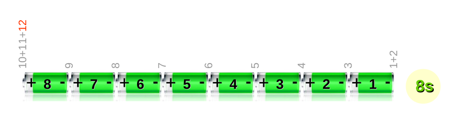
Notice that when you measure a cell say cell 3 you have wires #4 and #5 to take the measurement but those same wires are also used to measure the cell 2 and cell 4 voltage and also of course for cell balancing on those cells.
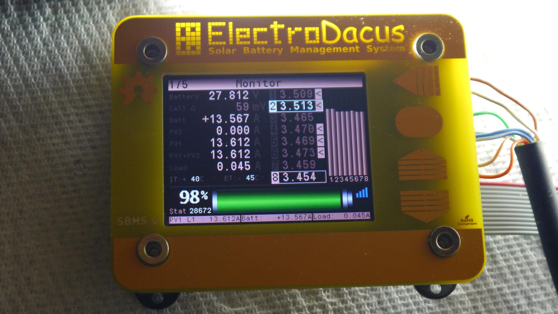
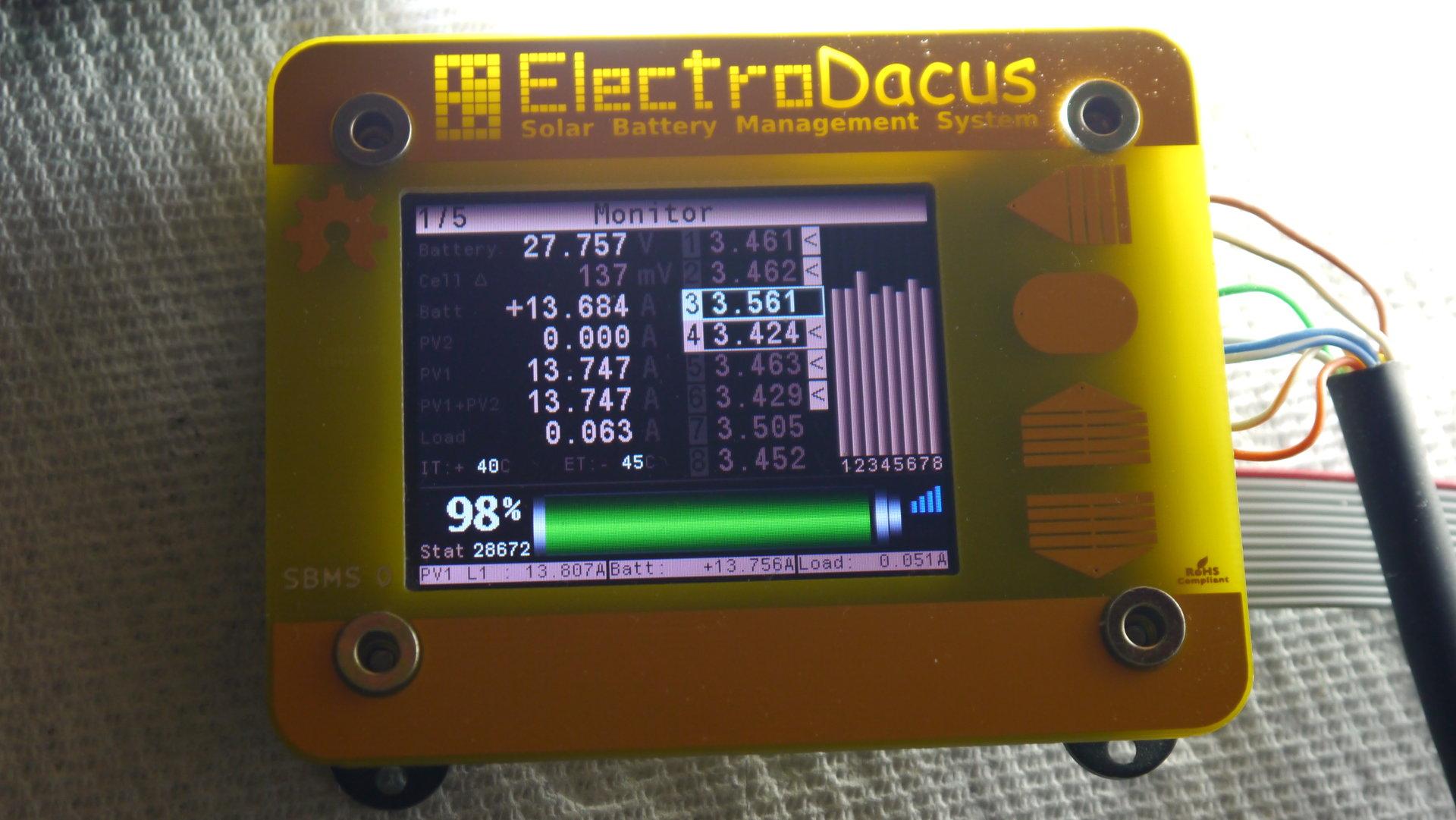
So in the photos below you can see first photo cell balancing not enabled (the 3 seconds break) and next photo took just a few seconds before the cell balancing was enabled.
The "<" symbol after cell voltage shows what cells need balancing so those cells will have about a 26Ohm resistor connected across them when cell balancing is active (last photo).
Now when cell balancing was not active cell 3 was showing the real cell voltage that is 3.465V and in next photo both neighboring cells 2 and 4 had cell balancing enabled and active that means both wire 4 and 5 had a voltage drop across them but due to the way the current flows trough that wire that voltage add's up to the cell voltage so at the end of those wires 4 and 5 the SBMS0 will read the cell 3 voltage + voltage drop on wire 4 + voltage drop on wire 5 thus it reads 3.561V so 96mV more about half of this on each the wire 4 and then wire 5 as both have about the same current flowing trough them and they are the same length the standard 6ft (1.8m) ribbon cable that the SBMS0 ships with normally. So 48mV on each wire and if you where to calculate this the wire is made of 7 strands of 36AWG that has 400mOhm/ft so since there are 7 of them that is about 57mOhm/ft * 6FT = 342mOhm
0.048V / 0.342Ohm = 140mA and that is about right as 3.5V / 26Ohm = 134mA
Cell 5 for example is cell balanced but so are the other two closest neighbors that share the same sense wire's so in this case wire drop on wires just cancels out as there is an equal current flowing in both direction trough each of this two wires 6 and 7.
Another case is cell 6 where only one neighbor (cell 5 is being balanced) so only one of the wires has a voltage drop the other one has not. 3.473V without cell balancing - 3.429 with cell balancing active = 44mV again close enough with what a single wire voltage drop will be this time you read a lower voltage so the wire drop subtract from the real cell voltage due to the direction the current flows trough the wire. Worse case will be a cell that is balanced and the neighboring cells do not then you will have about 96mV lower reading on that cells vs 96mV higher reading on cell 3 this worse case scenario will generate an max delta error of 96mV + 96mV = 192mV
Sorry my explanation is a bit long and maybe not made in the most efficient way.
Rob Duncan
Mar 23, 2020, 1:17:18 PM3/23/20
to electrodacus
Dacian,
My programming interface should arrive this morning. Have you posted link to new firmware version with programming instructions?
Dacian Todea
Mar 23, 2020, 1:36:49 PM3/23/20
to electr...@googlegroups.com
I just tested this weekend and all works fine as expected. I will post a link here in a few minutes.
Here is the link http://electrodacus.com/SBMS0/SBMS0v40p.zip
Software tools will depend on your operating system for Windows just download the tool from ST website https://www.st.com/en/development-tools/stsw-link004.html
If you are running Linux then get this https://github.com/texane/stlink
Procedure is
1) Connect BOOT0 (pin 5) to 3V (pin 12 for SBMS0)
2) Connect GND (pin 9 or pin 10) , SWK (pin 6) and SWD (pin 8) to the respective pins on your ST-Link programmer.
3) Power the SBMS0 by connecting the 12pin cell monitoring cable.
Rob Duncan
Mar 23, 2020, 2:39:30 PM3/23/20
to electrodacus
Looks like I should have previously installed the 10 pin flat ribbon cable header, and purchased suitable cable and connector. It's a little difficult to remove everything and tack on some temporary jumper wires.
My SBMS0 is not sitting on a open workbench!
My SBMS0 is not sitting on a open workbench!
I was under the impression this would be done thru the micro USB connector.
Dacian Todea
Mar 23, 2020, 3:07:53 PM3/23/20
to electrodacus
The ST-Link needs to be very close to SBMS0 as that is a fairly fast serial programming interface so no more than 20cm about the length of those included jumper wires so if computer is a bit further a USB extension cable will be needed.
The Micro USB is connected trough a digital isolator t the UART port of the microcontroller so not the programming port. The USB can be used for data logging or monitoring.
You will need to disconnect the 16pin connector and then connect to that for programming the microcontroller just GND, BOOT0 to 3V and the two serial and clock programming wires are needed.
Rob Duncan
Mar 23, 2020, 7:02:56 PM3/23/20
to electrodacus
So I need another 16 pin open end cable to replace the one that interconnects the two PCB layers? Any Pictures to ensure understanding?
Dacian Todea
Mar 23, 2020, 7:39:09 PM3/23/20
to electr...@googlegroups.com
Rob,
For just one time programming you should be able to just use that cable you get with the programmer.
I just made some photos maybe making things a bit more clear
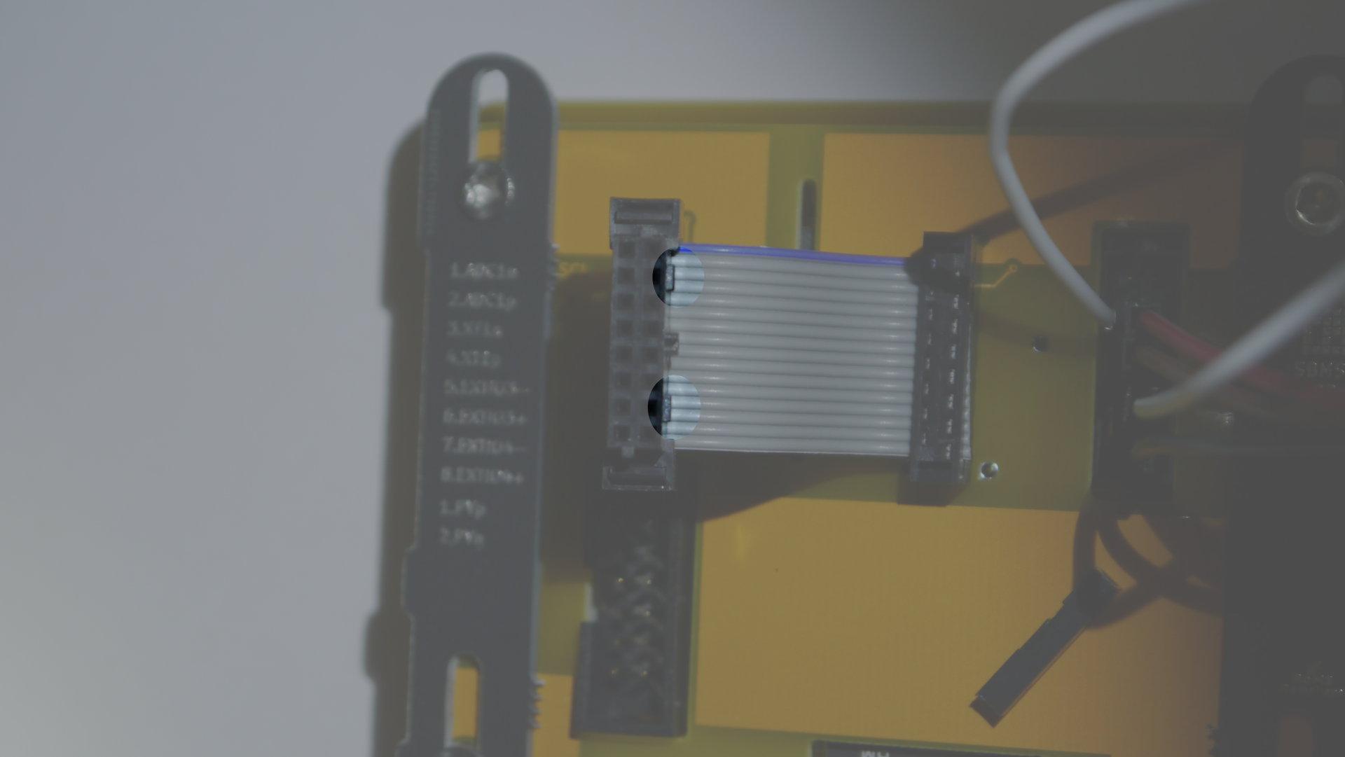
First image shows the pinout of that 16pin connector.
Second image shows the 16pin connector removed notice the highlighted clips so it will not be super easy to remove the connector but those clips will automatically release when you applied enough puling force. Maybe use a small lever under the corners of connectors but make sure not to brake the connector.
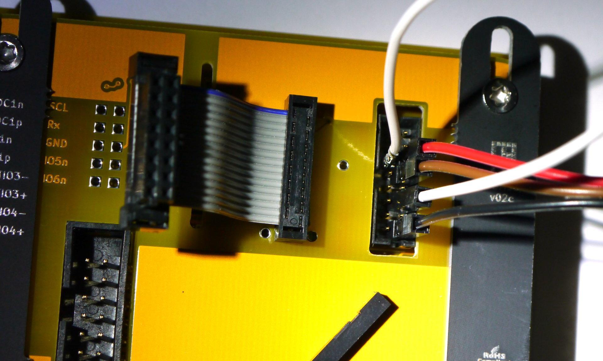
Once that is removed see the way I made the connections. The white wire shorts the BOOT0 (pin 5) to 3V (pin 12) this pullup will put the microcontroller in programming mode so when powering ON the SBMS will not boot.
Notice I removed the plastic shroud from one ends of the white wire link (on the BOOT0) as this wires are for 2.54mm (0.1") connectors and this is a 2mm pitch connector.
Then Black connector is connected to one of the GND pin 16 in this case then Brown connects to SWD (serial data pin 8) and the Red one connects to (clock data pin 6).
So this 3 pins will go to your ST-Link programmer.
Edit: Just made a test programming that SBMS0 and my china made ST-Link but should be about the same as your just double check the labels as maybe pinout may be a bit different.
It worked just fine with this wires.

Rob Duncan
Mar 24, 2020, 3:46:35 PM3/24/20
to electrodacus
Upgrade firmware ok, thanks to your hint about using .1" inch connectors. I will order 2 mm connectors for next time. Reset everything and was hopeful as the total voltage finally has exceeded 24.2V, then charging still prematurely stopped. I was expecting 24.6V. See attached images. Both OV and EOC settings are at 4.1V. Do you need me to reset and do another video showing the last minute of charging?
Should I trim what length I can from the balancing cable?
What is next?
Note my battery heating system is now working (60F), but just using plain water.
Dacian Todea
Mar 24, 2020, 3:59:19 PM3/24/20
to electrodacus
Rob,
Now the SBMS0 works as all the other SBMS versions and charging needs to stop at OV else voltage will exceed the set limit of 4.1V
After charge current stops the voltage will drop a bit that is related to the internal battery resistance and charge rate.
When charging with PV you may be able to get closer to 4.1V after charging stops as the charge rate may be lower at some points like end of the day or in cloudy days. So the 60mV was to be expected and if you want to push the battery higher then you can set the limit to 4.15V The length of cell balancing cable no longer has any impact on charging with the new firmware as the charging stops when highest cell is 4.1V for 6 seconds consecutive so not related to voltage drop due to cell balancing.
The cell was at 4.1V while you here pushing probably 25A or so and since voltage after charging stopped is 4.04V it means the 60mV was the voltage drop on the cells at 25A charge current it means internal resistance of that cell is 0.06V/25A = 2.4mOhm seems to be about normal for those type of high energy density cells the LiFePO4 has usually lower internal DC resistance depending on model but not that relevant.

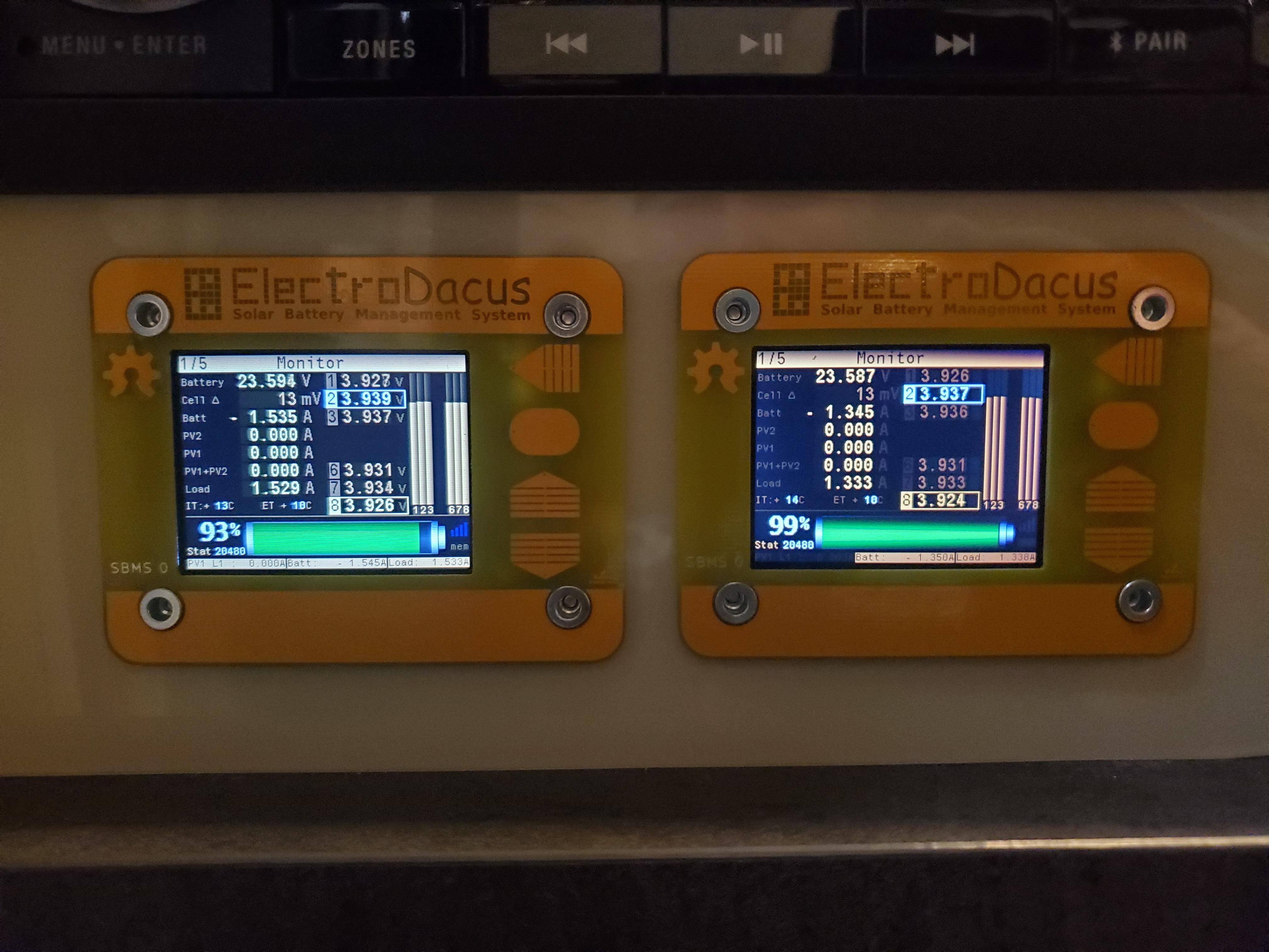
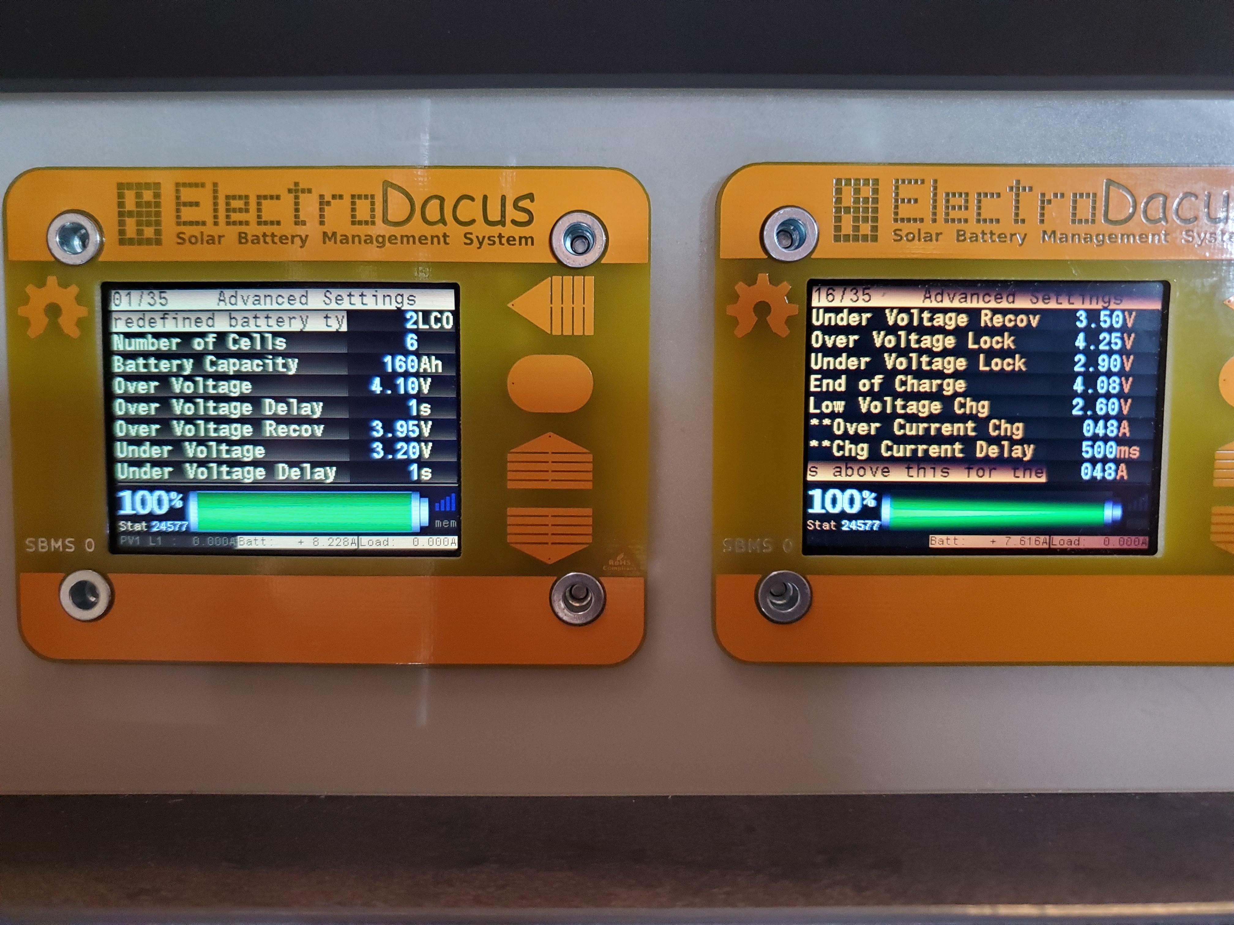
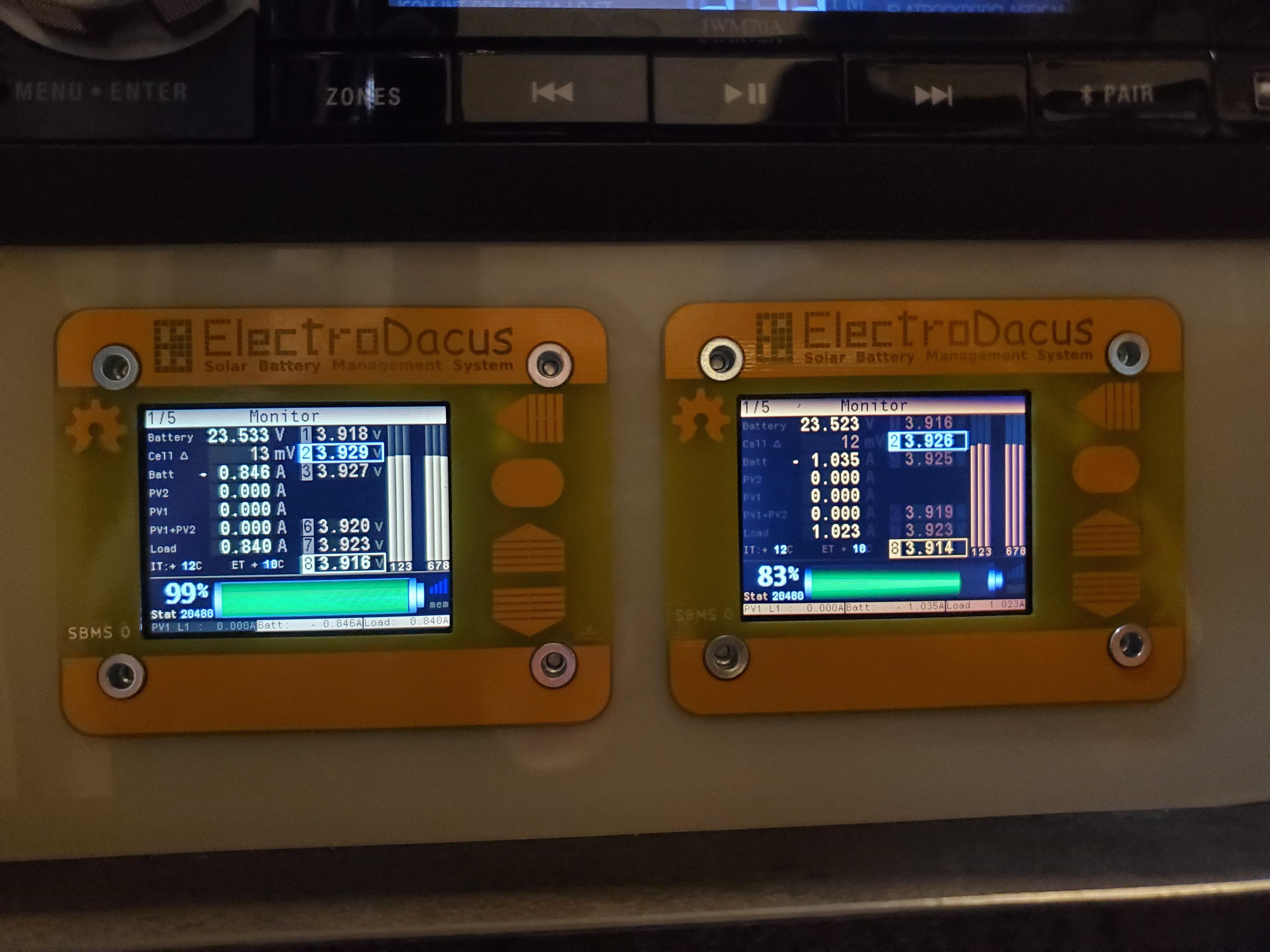
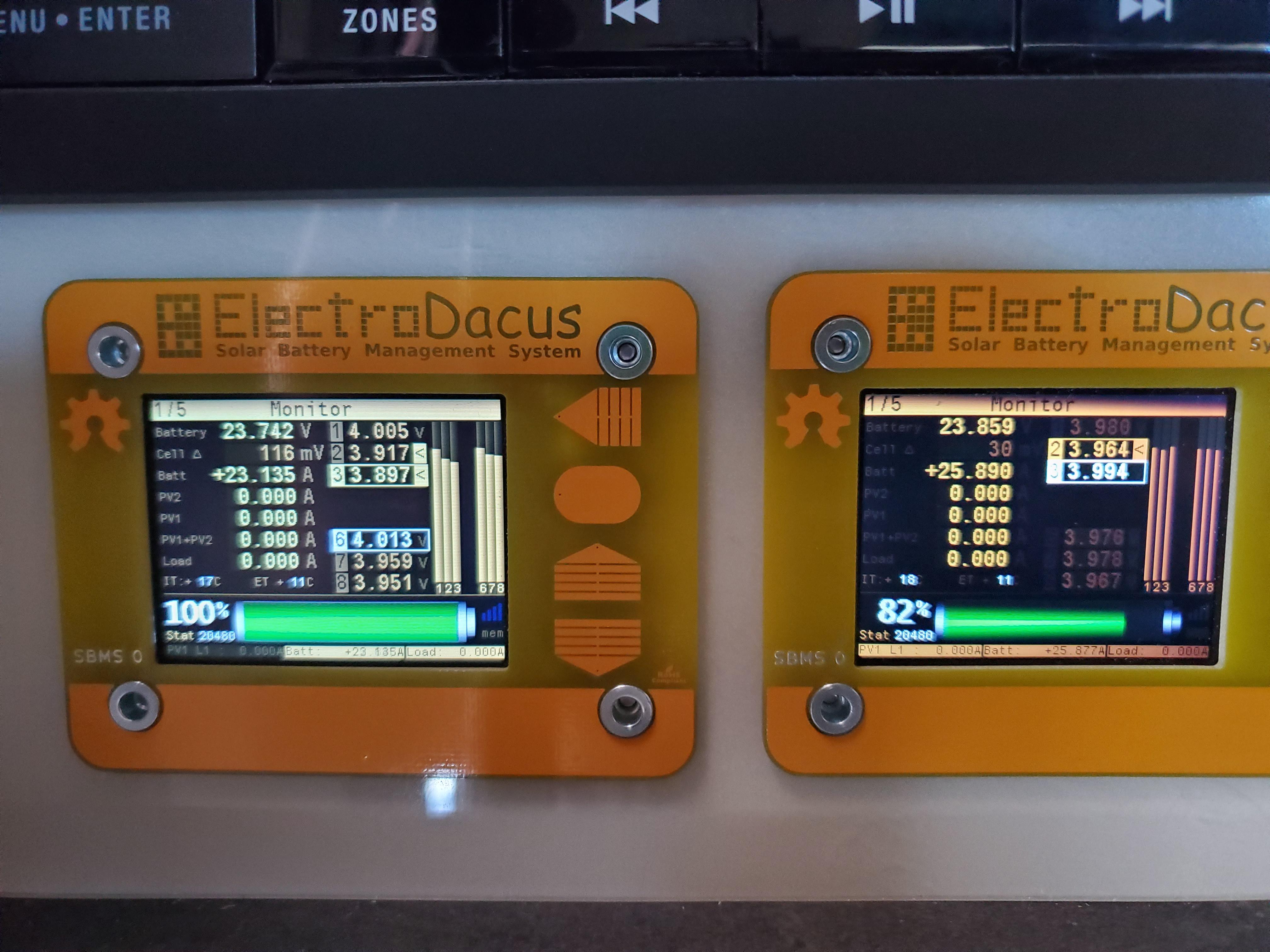
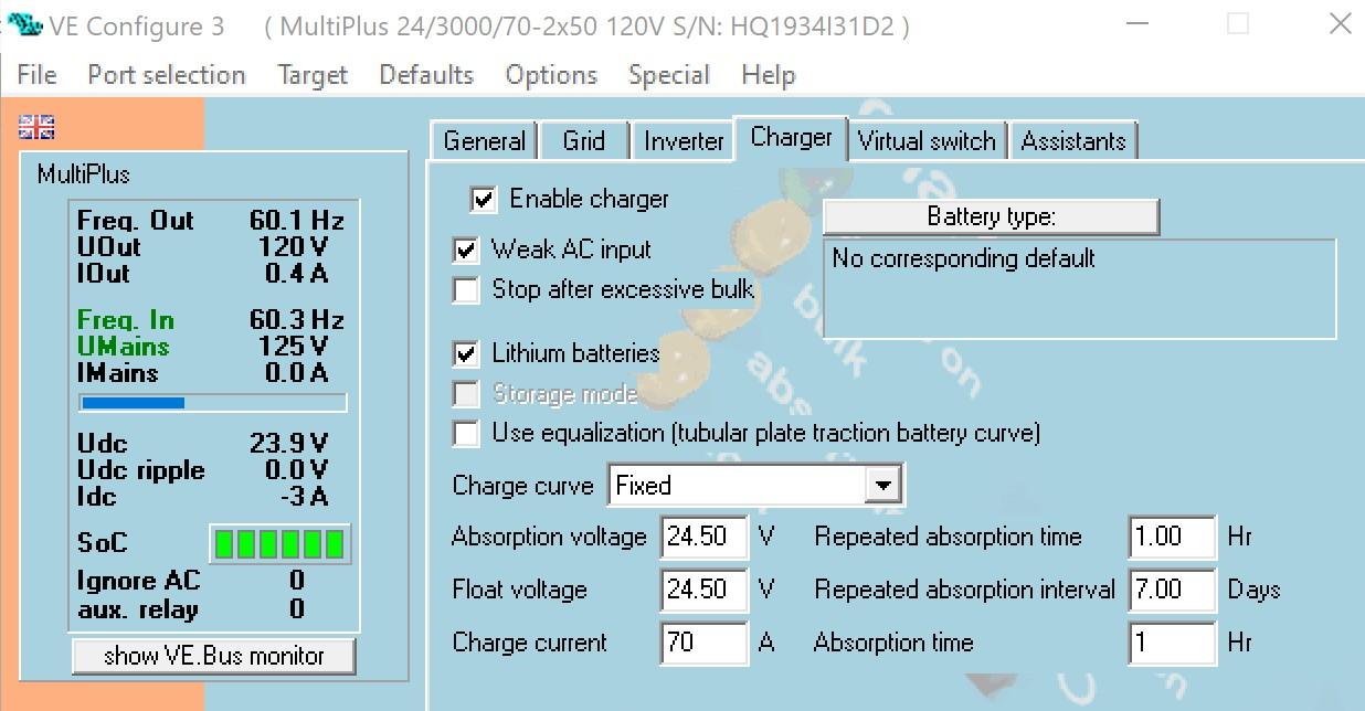
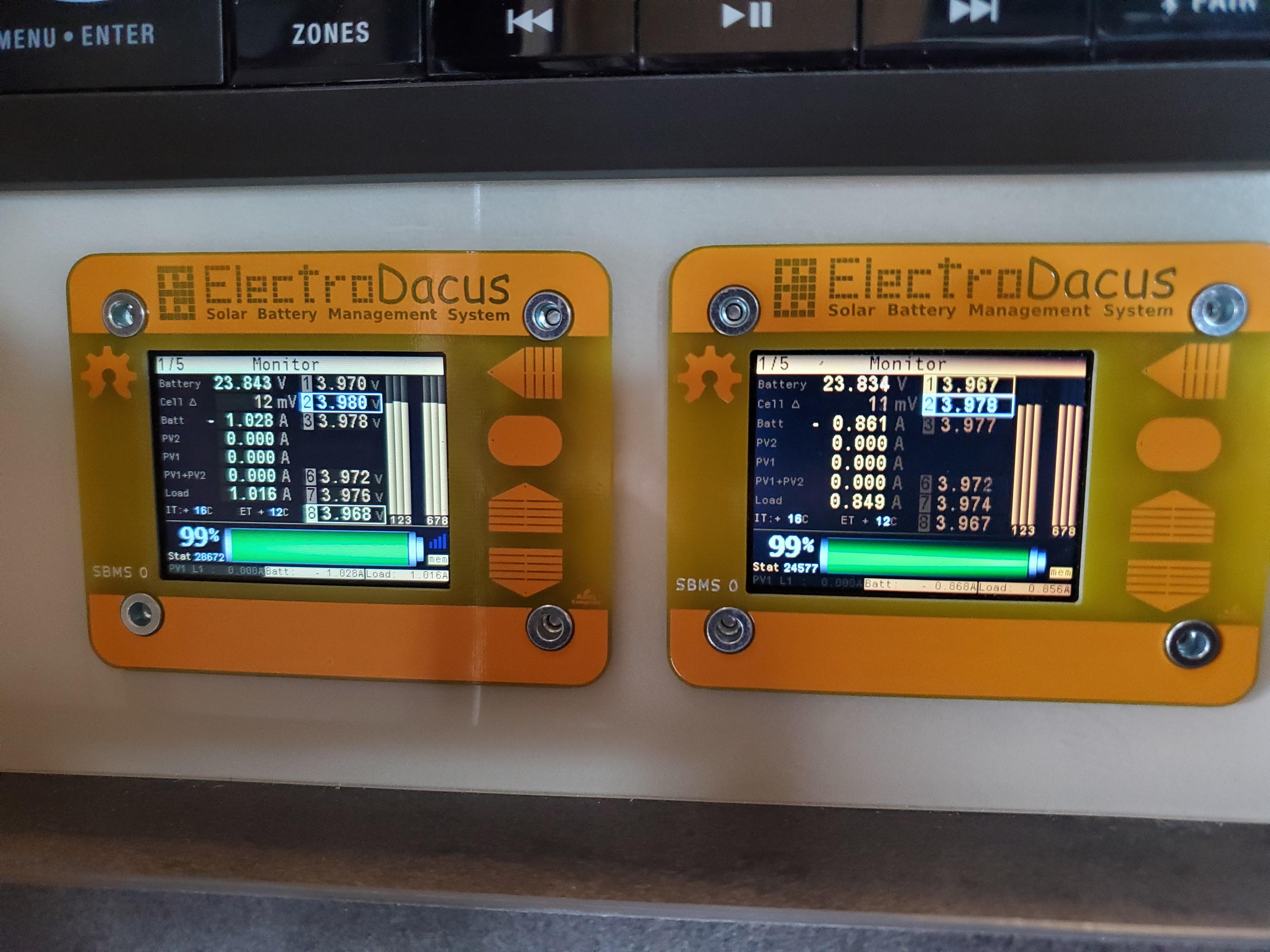
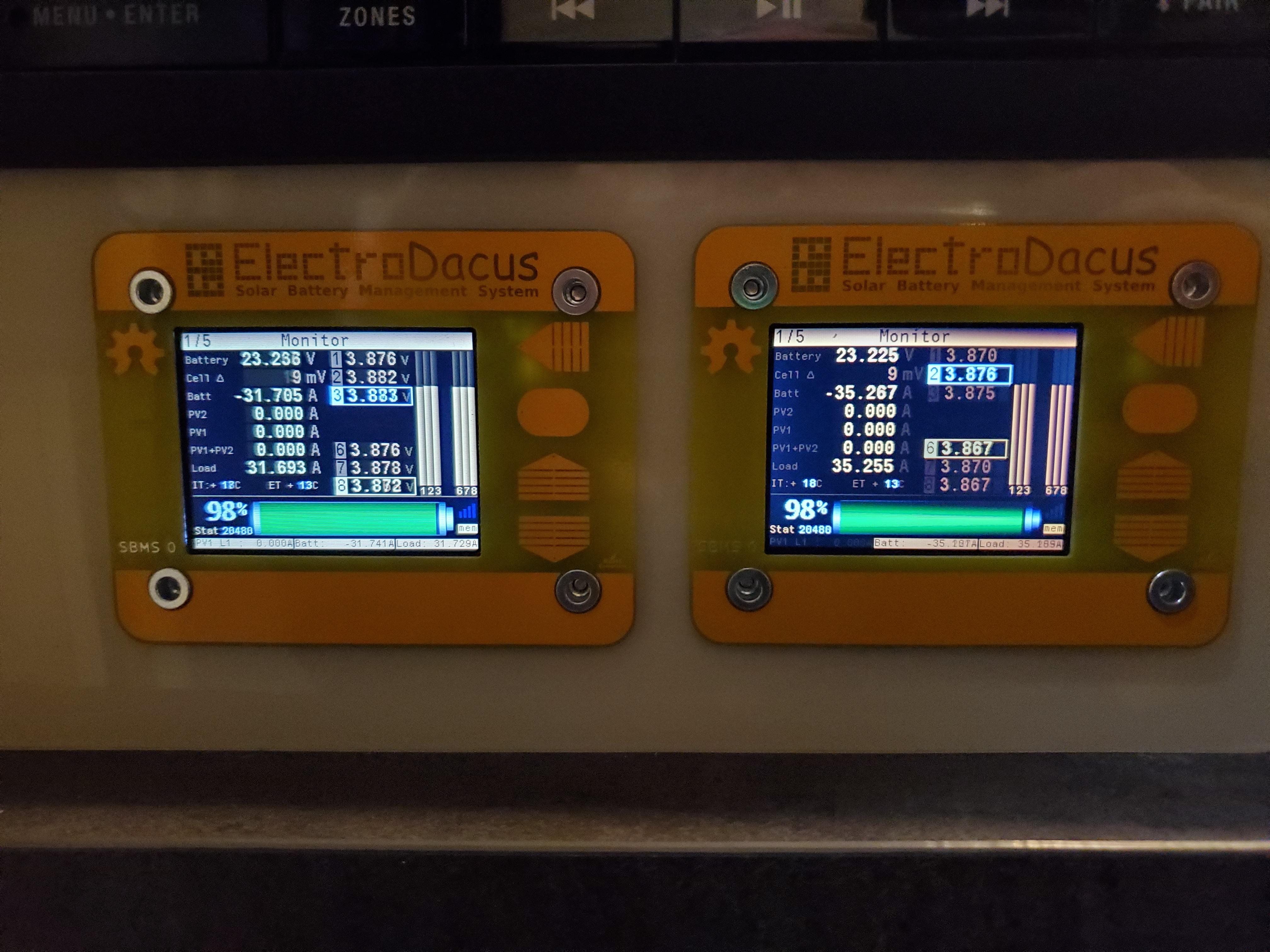
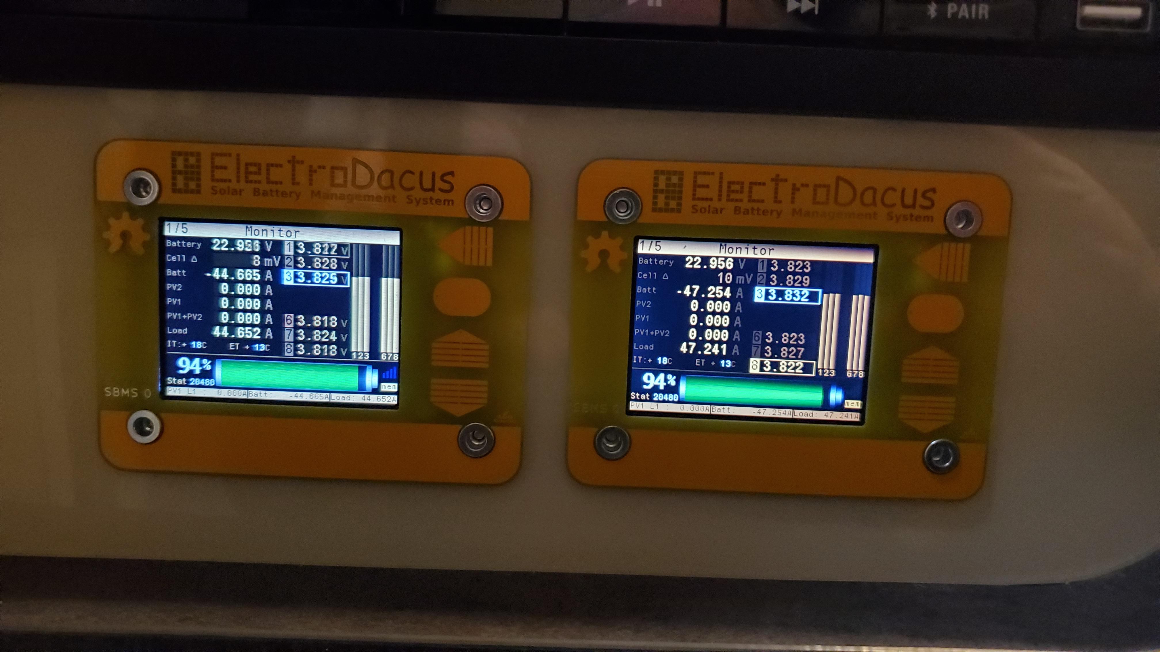
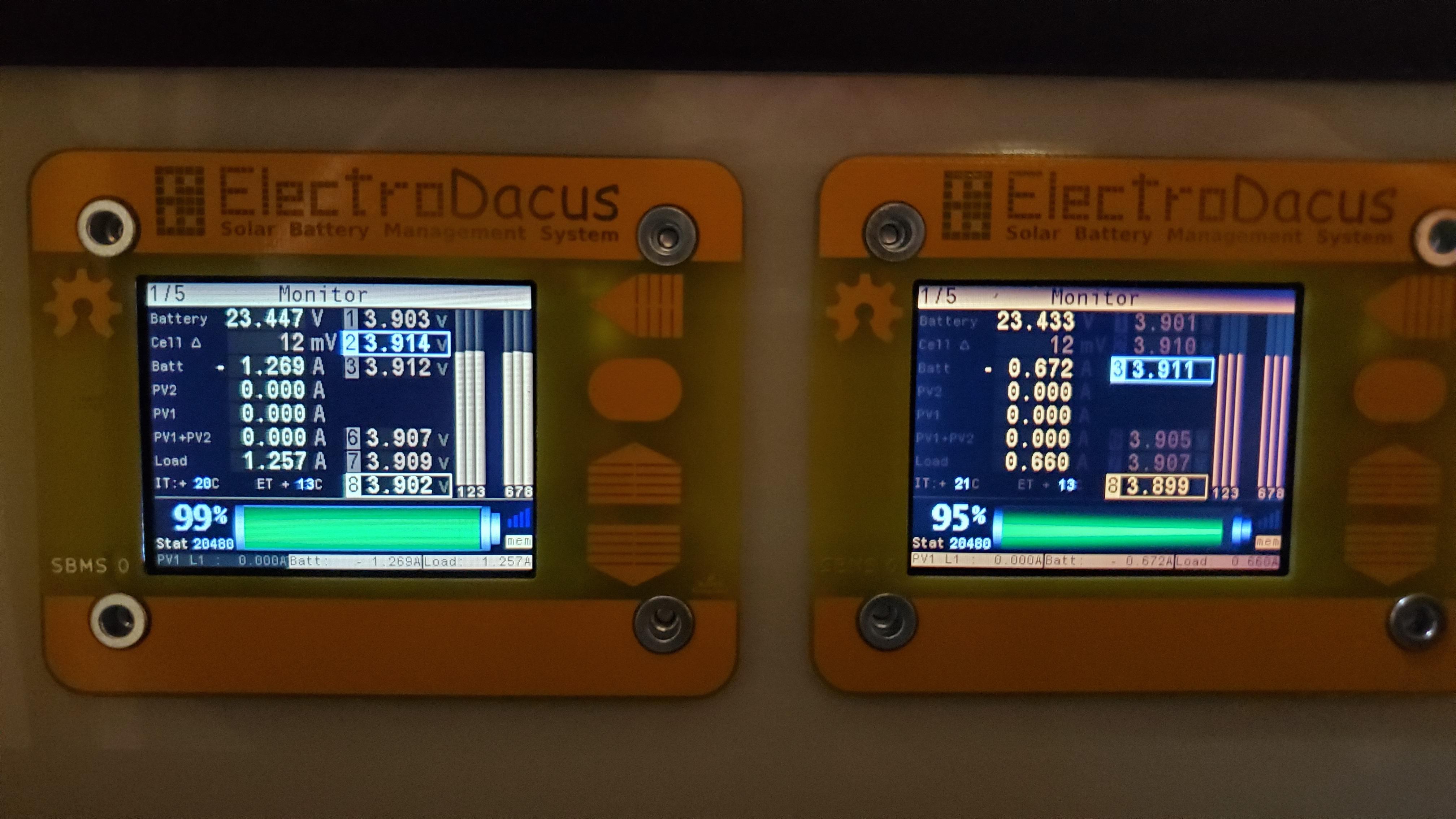
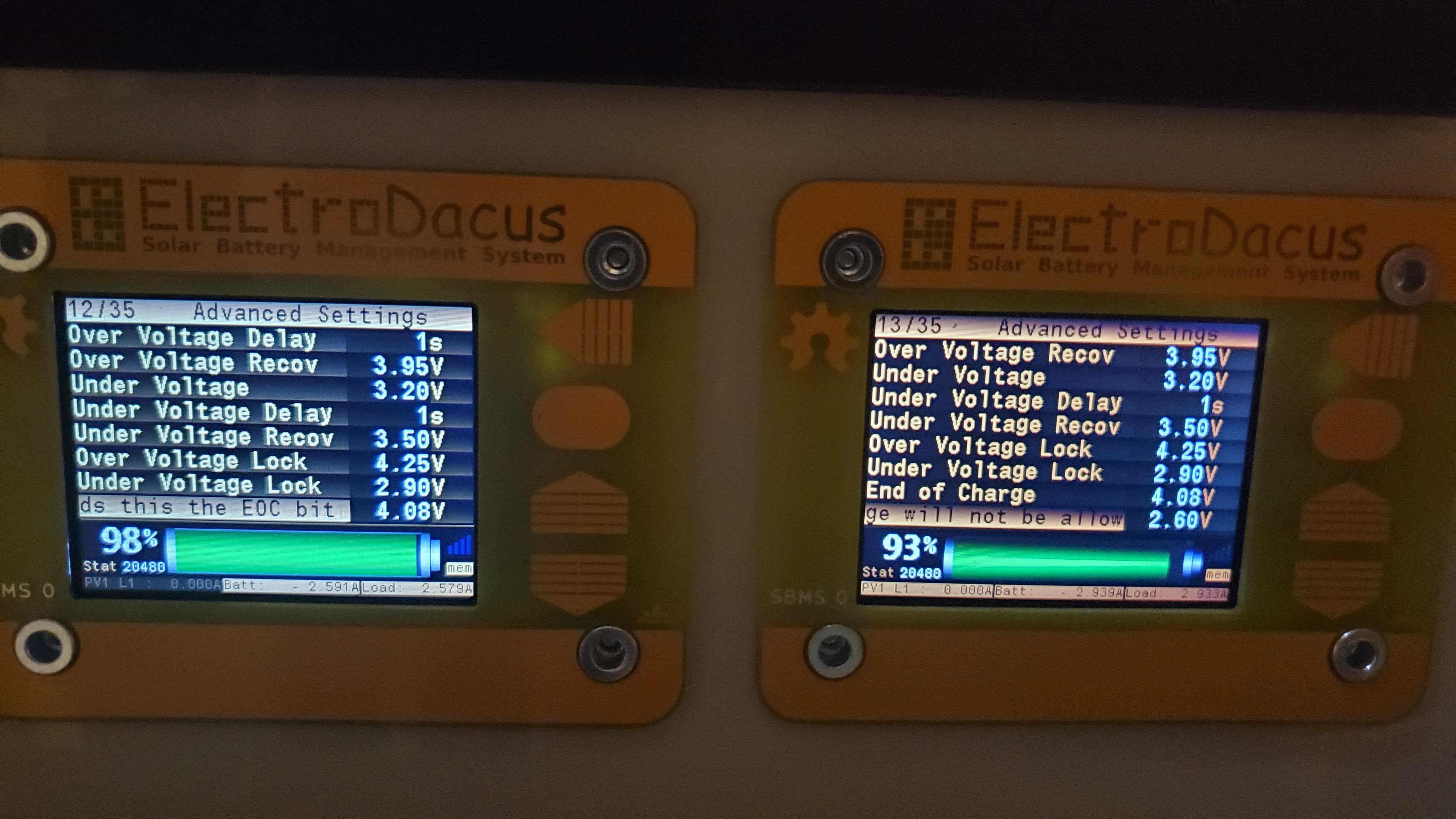
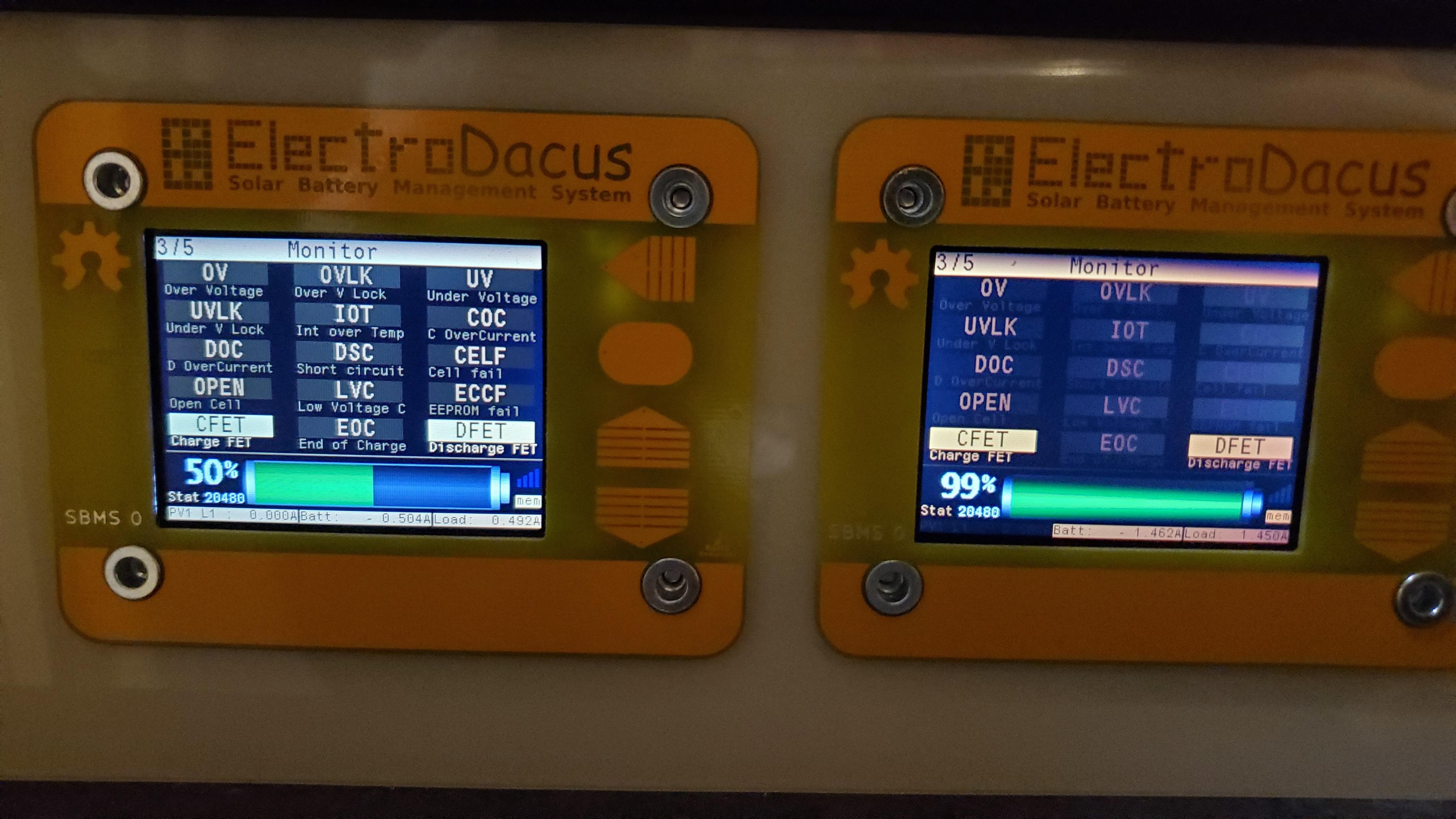
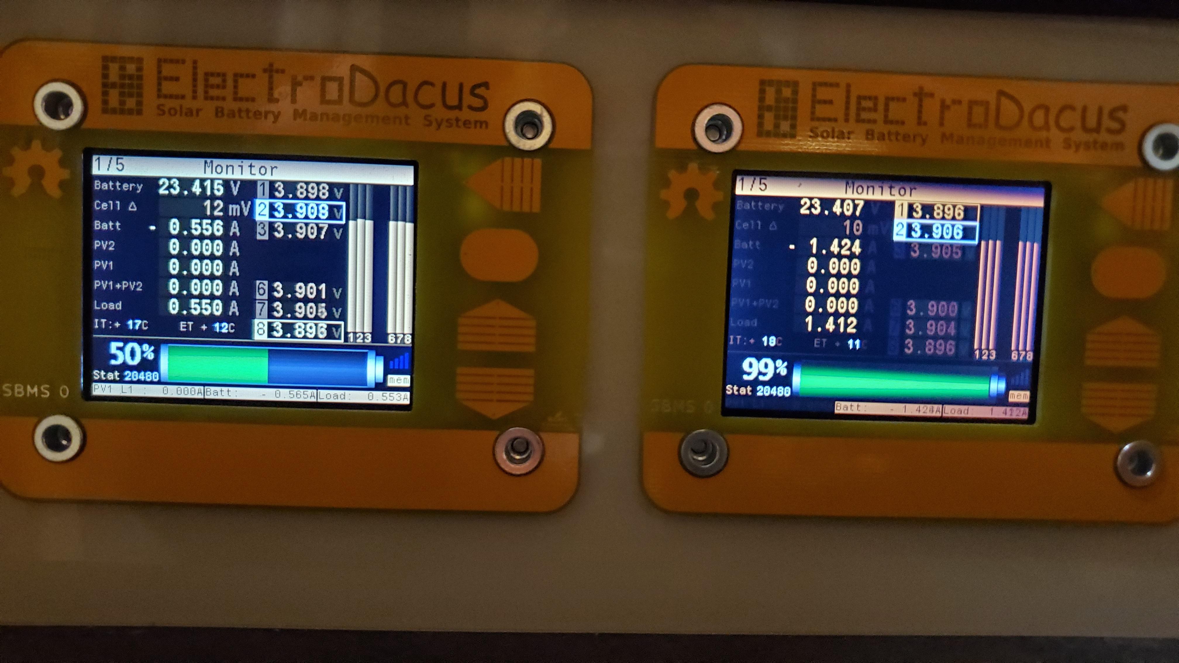
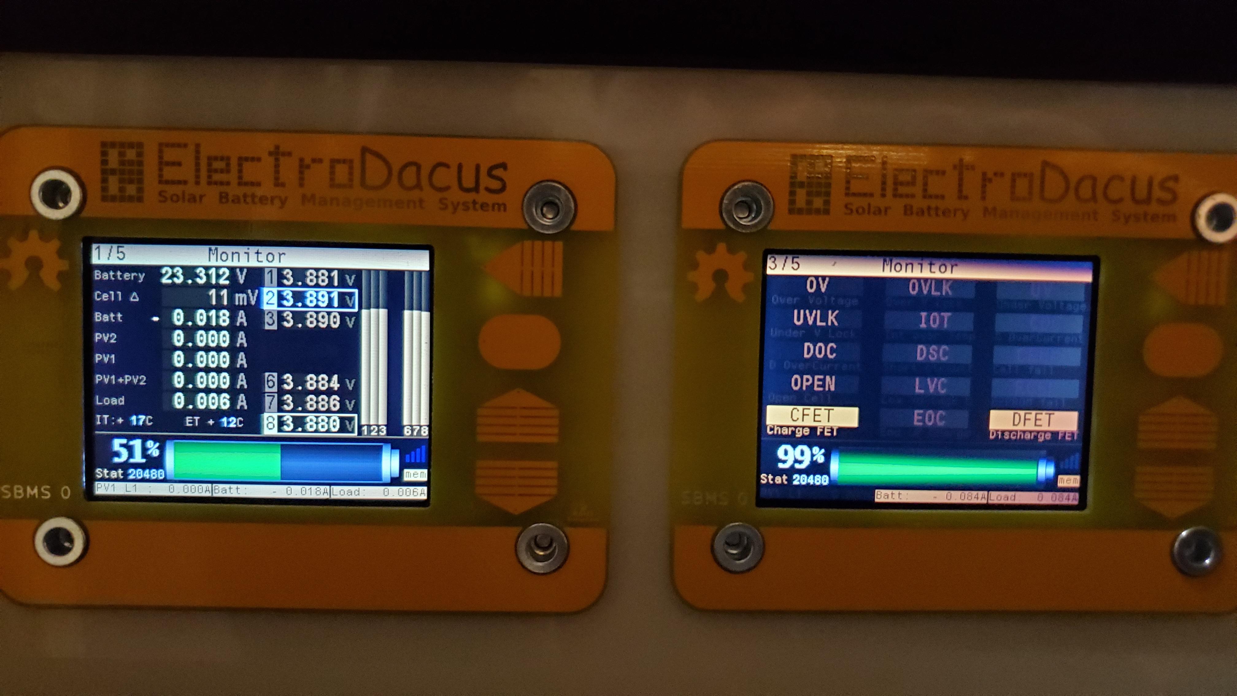
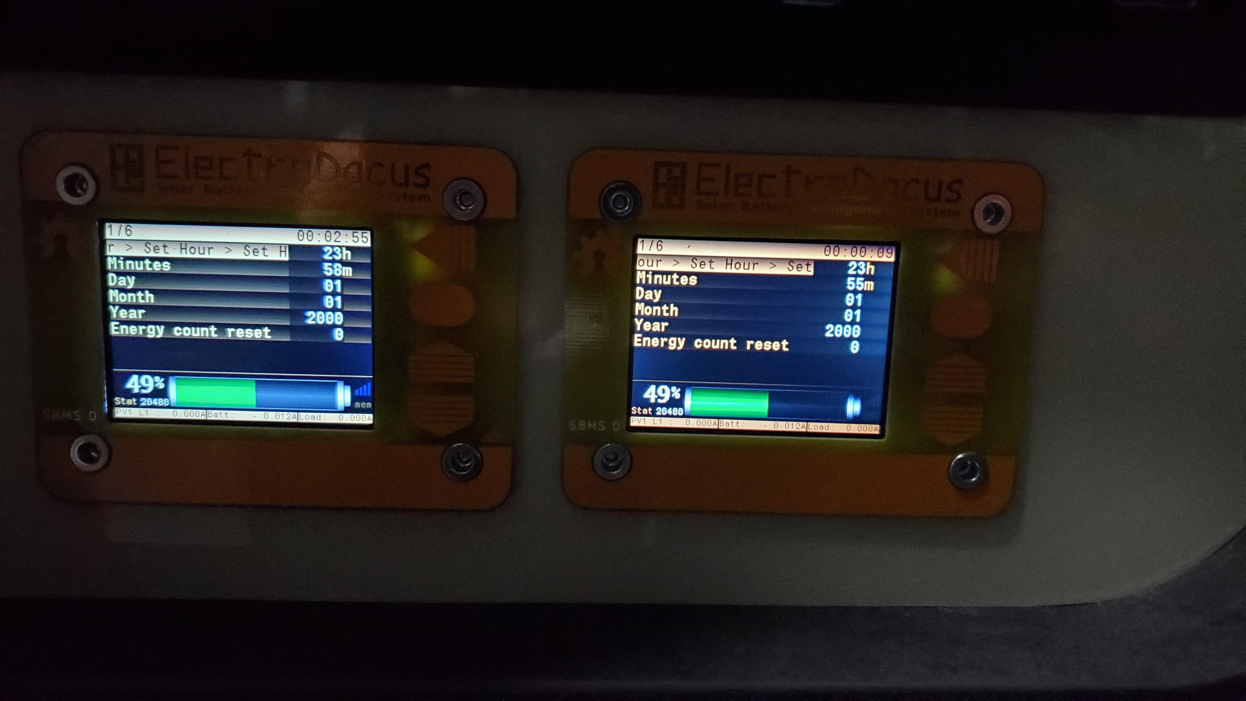
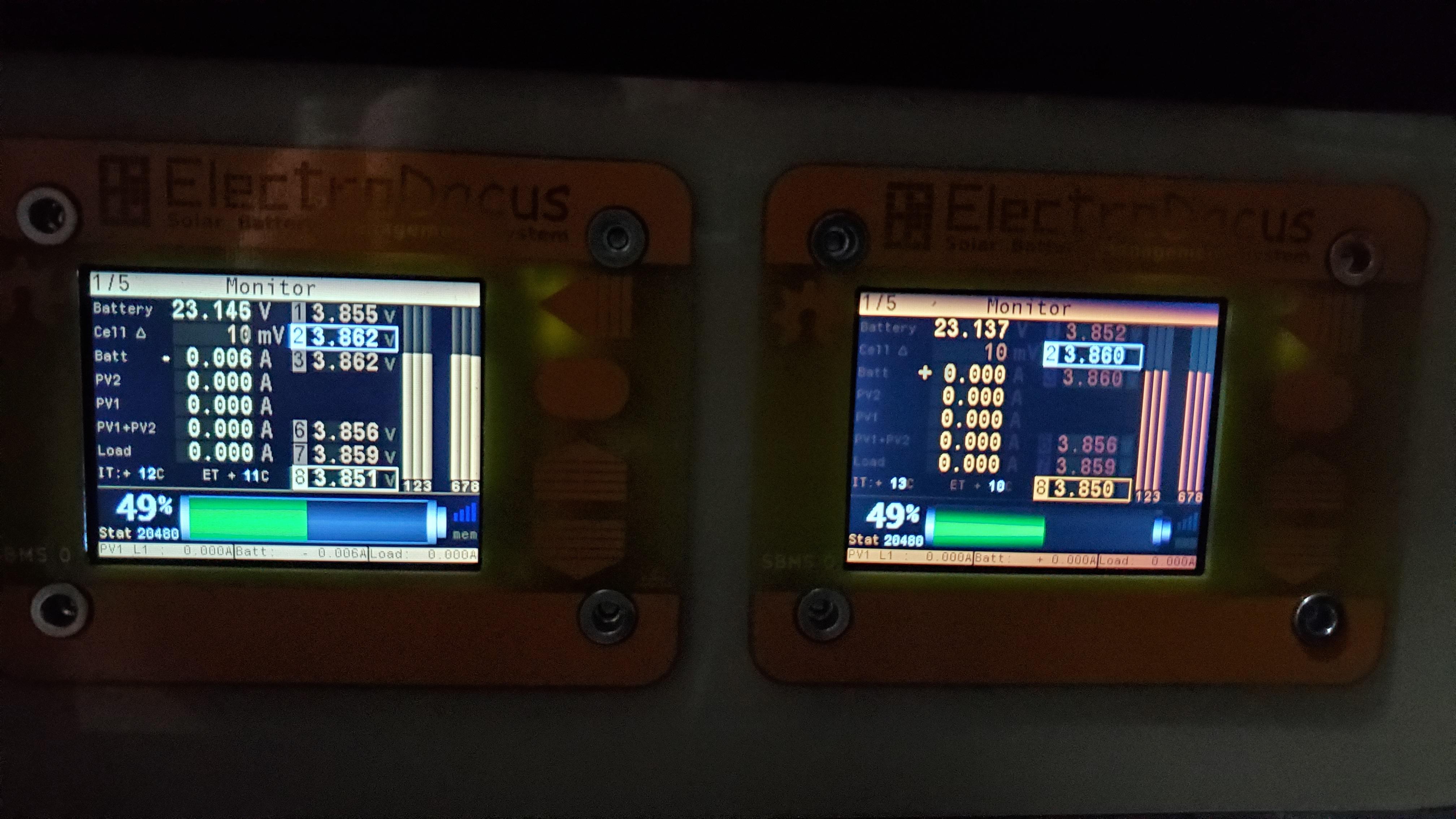
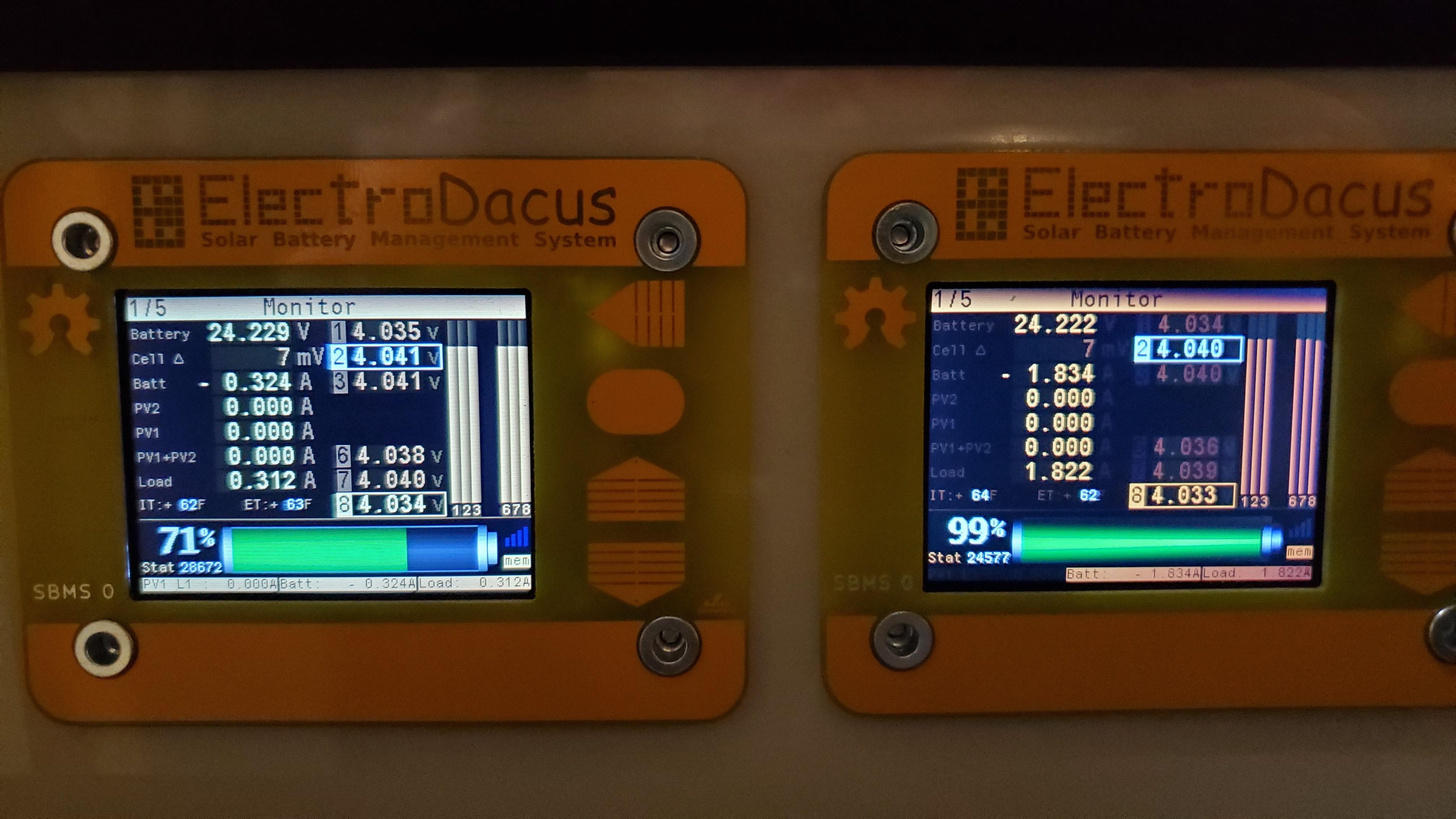
Harold
Jan 14, 2021, 4:04:27 PM1/14/21
to electrodacus
Hi.
Do we also power the SBMS40 /SBMS120 through the 12pin cell monitoring cable to update the STM µC ? (without the Batt+ connected)
Do we also need to neutralize the ESP32 (ESPFLASH/pin7 to GND) for the procedure on the STM µC ?
Dacian Todea
Jan 14, 2021, 9:47:16 PM1/14/21
to electrodacus
Harold,
The SBMS40/SBMS120 have a 10pin cable for cell monitor but that is not needed as the SBMS40/SBMS120 have an USB port that can be used to provide power to the STM32 so is simpler to just power using the USB cable for those models no need for battery.
No the ESP32 has no influence on the STM32 programming so no need to do anything with pin 7
Harold
Jan 16, 2021, 5:43:08 AM1/16/21
to electrodacus
Hi Dacian.
I've apparently managed to install stlink on my linux machine and correctly connected my ST-link v2 usb programmer dongle to the SBMS40's STM32 as show the return of the following command :
$ st-info --probe
Found 1 stlink programmers
serial: 0700390007000031354e4e4e
hla-serial: "\x07\x00\x39\x00\x07\x00\x00\x31\x35\x4e\x4e\x4e"
flash: 262144 (pagesize: 2048)
sram: 40960
chipid: 0x0432
descr: F3xx
Found 1 stlink programmers
serial: 0700390007000031354e4e4e
hla-serial: "\x07\x00\x39\x00\x07\x00\x00\x31\x35\x4e\x4e\x4e"
flash: 262144 (pagesize: 2048)
sram: 40960
chipid: 0x0432
descr: F3xx
I've the sbms120-v50d.bin file at hand.
But now, I don't know what command to run to update the STM32 :
st-flash ??? sbms120-v50d.bin ????
Dacian Todea
Jan 16, 2021, 1:15:53 PM1/16/21
to electrodacus
sudo st-flash write <file_to_flash>.bin 0x08000000
Dacian Todea
Jan 16, 2021, 1:16:49 PM1/16/21
to electrodacus
sudo st-flash write sbms120-v50d.bin 0x08000000
Harold
Jan 16, 2021, 2:47:23 PM1/16/21
to electrodacus
That software "sbms120-v50d.bin" is for all current SBMSes despite it's named sbms120-v50d.bin, including SBMS120, SBMS 40and SMBS0, Right ?
Dacian Todea
Jan 16, 2021, 7:54:40 PM1/16/21
to electrodacus
Harold,
No that is specifically for the SBMS120. While all models share the same source code in the code you select the model before compiling as there are differences so then the compiled binary file is only good for the model described in the name SBMS120 in this case.
Even for the two versions of SBMS0 there will be separate files like
http://electrodacus.com/SBMS0/sbms0-v02b-v50d.bin.zip for the older version of SBMS0
http://electrodacus.com/SBMS0/sbms0-v03d-v50d.bin.zip for the new v03d version of SBMS0 but that already comes with this latest version.
http://electrodacus.com/SBMS0/sbms40-v50d.bin.zip this is for the SBMS40
http://electrodacus.com/SBMS0/sbms120-v50d.bin.zip and finally for the SBMS120 that you already have.
For SBMS0 the link is in the user manual I just did not had the time to update all the user manuals and will do so at some point when I'm less busy.
Most people have no reason to update as none of the earlier version have any critical faults they just do not have a few of the newer futures/settings but nothing super exiting.
Most people have no reason to update as none of the earlier version have any critical faults they just do not have a few of the newer futures/settings but nothing super exiting.
Harold
Jan 17, 2021, 5:54:45 AM1/17/21
to electrodacus
As I have a SBMS120 (presently in use) and a SBMS40 (for spare) I've just flashed the SBMS40's STM32 that I have on my bench with its proper firmware ( http://electrodacus.com/SBMS0/sbms40-v50d.bin.zip ) for test purpose. That SBMS40's ESP32 was previously flashed with Robert's/Amaguedon ESP32 firmware and it did work very well.
After flashing the STM32, I couldn't then get a proper connection through WiFi at 192.168.4.1. It was very unstable, it wouldn't give me the time to set it up through Robert's/Armaguedon web page.
So I had to flash the ESP32 again with Robert's/Armaguedon firmware.
It now seems back to normal with last STM32 and ESP32/Armaguedon firmware.
Dacian Todea
Jan 17, 2021, 2:58:42 PM1/17/21
to electrodacus
Harold,
I do not see how the last firmware version will have influenced in any way your WiFi firmware. Problem was likely unrelated.
Reply all
Reply to author
Forward
0 new messages