Please check my plans

373 views
Skip to first unread message

Leon Close

unread,
Jul 3, 2021, 7:01:49 AM7/3/21
to electrodacus

I'd really appreciate any feedback on this draft diagram. It's the DC stuff only at this point. Is there anything obviously wrong or missing?

I know you all know this, but this forum has a wealth of good information, and Dacian provides the best customer support of any product or business I have ever had anything to do with.

Thank you!
System 1.png

Plamen

unread,
Jul 3, 2021, 7:17:34 AM7/3/21
to electrodacus
Hi Leon,
 I'd move the fuse on the positive line of the inverter. If it gets blown You'll get the PV open voltage straight to your loads/inverter.

Dacian Todea

unread,
Jul 3, 2021, 12:30:21 PM7/3/21
to electrodacus
As Plamen already noted you will want separate fuse for the charge source and for Load either on positive or on negative but separate.
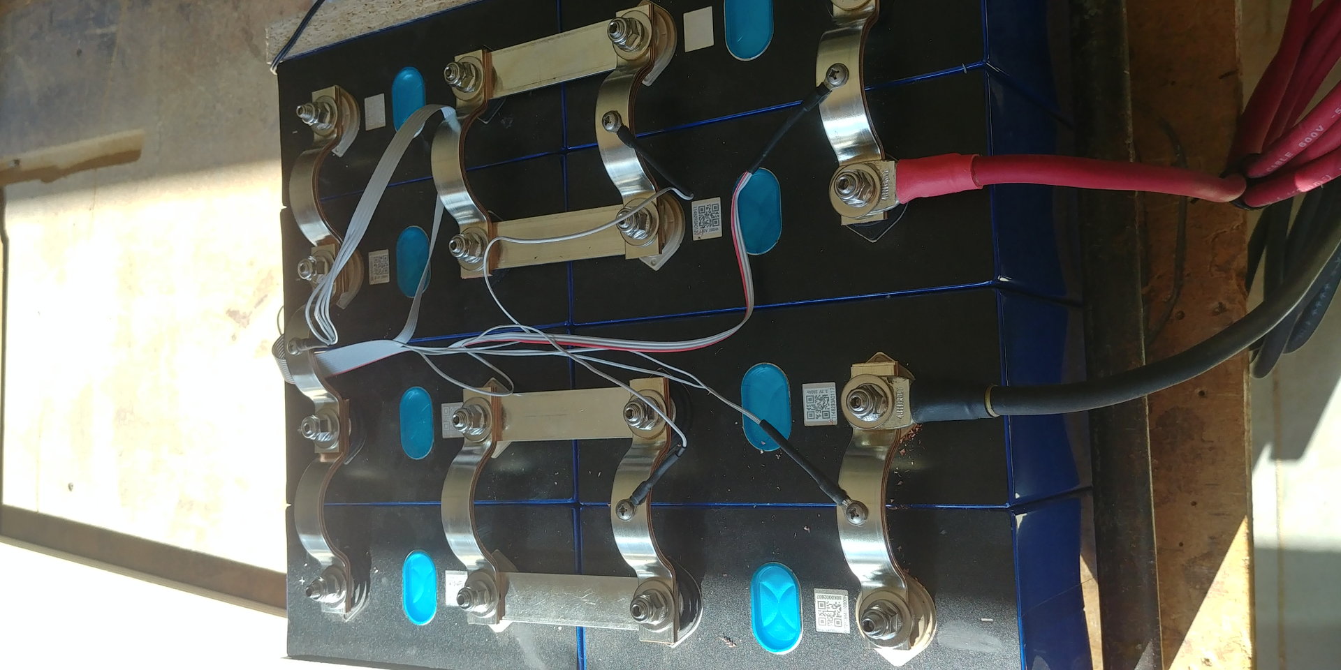
Also if you have the space rotate the cells 90 degree that way you have better connection between cells.
Bellow is a smaller 4s2p battery but it illustrates what I mean.

4s2p-lifepo4-2.jpg


Leon Close

unread,
Jul 3, 2021, 9:14:34 PM7/3/21
to electrodacus
Hi Plamen, I will move the fuse to the positive line. Thanks. By the way, would you still be happy with those cheap TOMZN breakers for PV input?

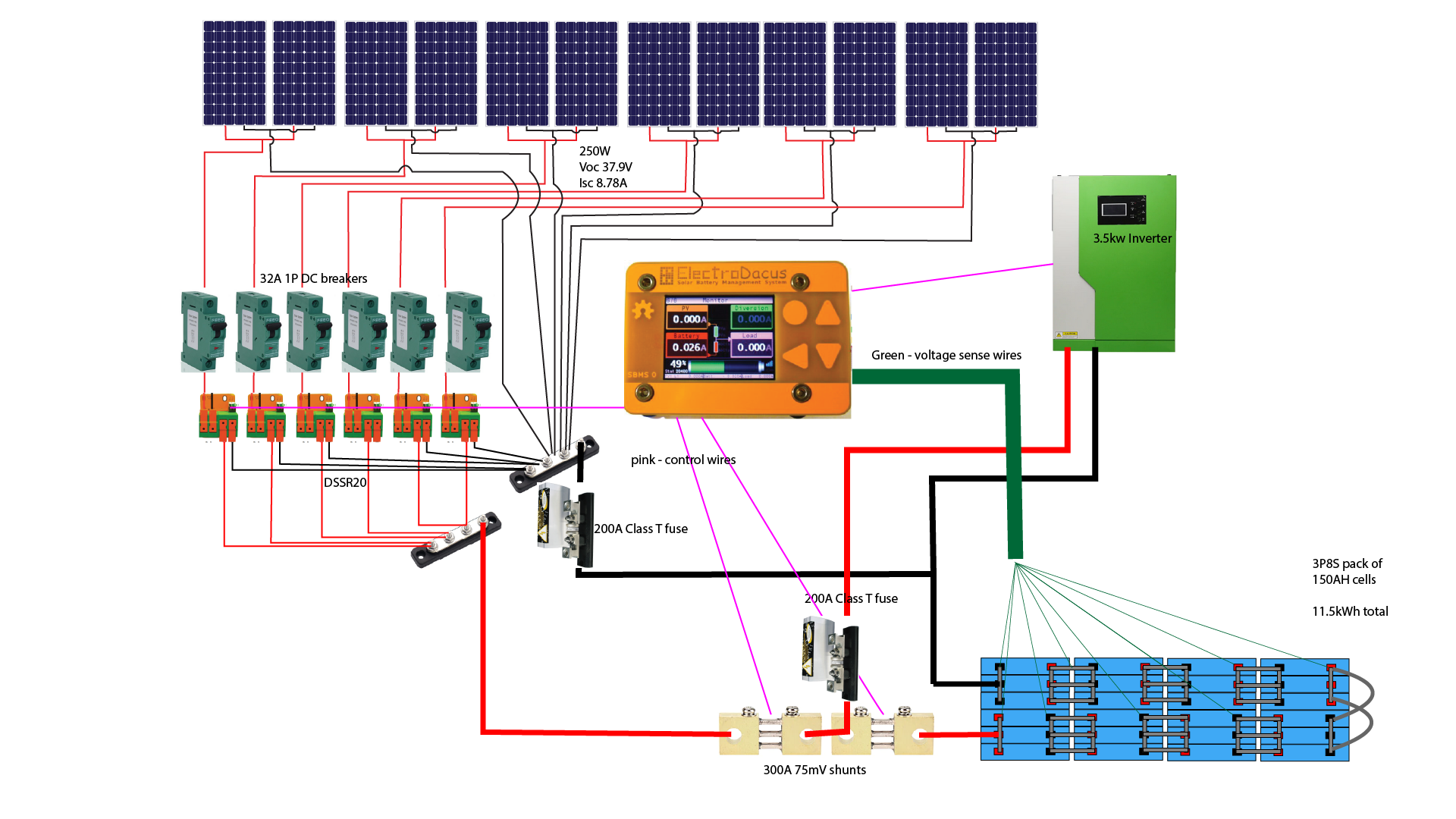
Hi Dacian, I have placed another Class T fuse in the negative line for the charge source. Would it be better in the positive line next to the PV shunt?

System 1-2.png

I see what you mean about the battery design. In my original layout, I assume the cells that are most directly connected would end up doing more work. It's a shame, since the form factor would be very convenient for me.

With some re-building, I can make the arrangement in the diagram above work. How much better do you think this would be? I would probably make the curved links at the right end from cable with crimped lugs, the same as the main battery cables to the inverter.


Thinking more about fusing now:
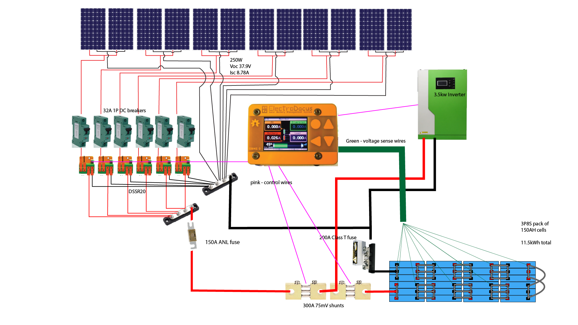
If the Class T went back to the negative battery terminal, it could protect all the wiring from excessive current delivered by the battery. The potential solar output still needs protection, but this should only need to interrupt the max output of the solar array. 8.78 x 12 = 105.36A. No need for a Class T here, right? Where I live, the coldest it ever gets at dawn in midwinter is about 8°C. With any sunshine it is never that cold, so I don't think I need a significant temperature correction factor. Would a fuse value of 150A be about right? What type of fuse would be best? ANL is less than half the price of Class T for Blue Sea Systems brand, when both holder and fuse are considered.

Like this:
System 1-3.png

Thanks for all your support.

Leon.

Dacian Todea

unread,
Jul 3, 2021, 9:40:05 PM7/3/21
to electrodacus
Leon,

I will say new battery setup will be about 3x better :)
Charge fuse can be either on negative or on positive the important thing is that it has separate fuse from the fuse load and there is no battery fuse just fuse for load and fuse for charge sources.
Also positive fuse will be more elegant as the SBMS system is designed as common negative so all disconnection and measurements are made on the positive side allowing the negative to be undisturbed.
If a fuse disconnects the battery from the system as it will be the case in your last diagram the DSSR20 will push full open circuit voltage in to your inverter likely damaging the inverter.
Neither the SBMS nor the DSSR20 knows that your battery is no longer connected in circuit as SBMS0 sees the battery trough independent sense wires and the DSSR20 just gets signal from the SBMS0 to charge assuming battery is not full when the fuse fail happens.
Having only separate fuses for charge source and for Load if any of them fails it will not affect the other part of the circuit. 

Plamen

unread,
Jul 3, 2021, 10:28:21 PM7/3/21
to electrodacus
Leon,
   I have 16A of those TOMZN breakers for my first PVs. Then bought 32A for the rest. So far don't have any troubles there. It's just one PV per breaker. I use them mainly for PV disconnect. The downside is that they are polarised. Will not protect if current flow backwards. Hopefully it will never happen. I'm with SBMS120 that has ideal diodes on the PVs. Same way as DSSR20/50 have ideal diodes to prevent that backflow. So You can use them too. 
     Maybe it's just on the diagram and You're aware, but just in case. Those Fuses/Automatic breakers are to protect the cables. And as the battery is the 'danger' putting the two fuses next to the shunts is the best. 
     About the right fuse. A few weeks ago I had my main(DC loads/Inverter) fuse blown with about 4.2kw load on the inverter. It was stamped as 250A. I changed it with 500A but still it gets too hot just with 90A load.
At the end when You test it You'll know. Personally I don't feel comfortable with a fuse that is well calculated and did not blow but gets so hot that i can't touch it. And as the cables i have there are 2 AWG i'll change the 500A with even bigger.

Petrus Potgieter

unread,
Jul 4, 2021, 4:40:16 PM7/4/21
to electrodacus
Hi Leon,
You should also add a 4,7kOhm resistor to EXTIO4+.

The diagrams in SMBS0 v03d manual does not show this because it is for the previous version of DSSR20 without diversion but the manual for DSSR20  v04d and DEXT16 has this info.
I did not understand why the DRRS20 did not want to switch on at first.

DSSR20 resistor.GIF 

Leon Close

unread,
Jul 5, 2021, 9:23:41 PM7/5/21
to electrodacus
Thanks for the tip about the resistor. I probably would have missed that!

Plamen - Interesting to hear about the fuse getting hot. Not sure how I would deal with that. I suppose one would have to have large cables to allow for a sufficiently sized fuse. Regarding the unidirectional PV breakers, perhaps I should just use some cheap breakers as switches and add 10x38mm or similar fuse holders in series for bi-directional protection?
Dacian - Just out of interest, what would happen if a DSSR20 saw overcurrent? How would it fail?


I am now considering two main options for protecting the wiring between battery - inverter and battery - charge bus.

Option 1: 150A MRBF fuse on positive charge cable. 225A Class T fuse on negative battery terminal, before branching to inverter and charge bus. In a catastrophic fault on the charge circuit, the MRBF would blow. If it could not interrupt the current, the Class T would also blow. Class T would blow in case of short on inverter circuit.

Option 2:  225A Class T fuse on inverter side of shunts, another type of HRC fuse, 150A on charge side of shunts. This seems preferable, but I am yet to find a suitable fuse for the charge side. Class T seems to only be available down to 225A in Australia.

Do either of these sound viable? Option 1 is easier to implement.

Dacian - Just out of interest, what would happen if a DSSR20 saw overcurrent? How would it fail?

Yet another question - It has occurred to me that the simple plated copper bus bars that came with my cells will not work in the improved battery configuration. I do, however, have plenty of aluminium plate. Would large bus bars connecting groups of 6 cell terminals as in this sketch work? It seems like this would reduce corrosion potential by avoiding dissimilar metals in the system. The extra lines on the top left one represent possible cuts to allow some slight flexing of the plate to account for slight misalignment between cells and reduce mechanical stress.
big bus bars.PNG
Thanks everyone for your patience and advice.

Leon

Dacian Todea

unread,
Jul 5, 2021, 11:47:57 PM7/5/21
to electrodacus
Leon,

The DSSR20 can not see over current if installed correctly. Solar panels are constant current source so even if you short circuit a panel it will not output more than the spec.
And current from battery to the PV side can not flow trough DSSR20 as there is a build in ideal diode.
That 150A fuse in your circuit is there to protect the cable between the fuse and the positive charge buss bar.  There is nothing else that the fuse will protect. So that fuse will need to be immediately after the PV shunt
The other fuse should be to protect the inverter wires ideally on the positive wire just after the battery shunt as it shows in your first diagram.
So you can have an electrical box immediately next to battery positive terminal and have there the two shunts and the two fuses and everything will be protected (mostly the wires as that is what the fuses are for).

Leon Close

unread,
Jul 6, 2021, 6:12:11 AM7/6/21
to electrodacus
Just re-writing a message I thought I had sent, but have lost somehow.

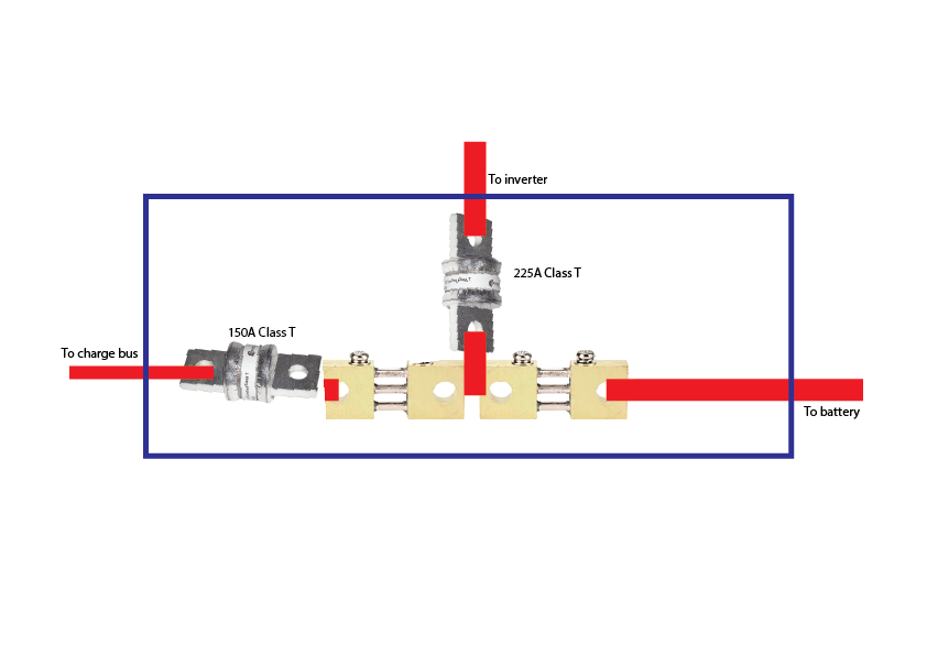
Dacian, if I understand correctly, this sketch is the preferred arrangement. The blue rectangle is the electrical box you suggest. The only problem with this is that it is difficult and expensive to obtain the 150A fuse in Australia.
fuses 1.png
I think this arrangement would also provide the protection needed. There is still a HRC fuse in the current path of a short in either circuit and the MRBF would look after an overload on the charge side (e.g. battery connected with high solar output). I can get all the parts locally. I do not understand what problem is caused by having the fuse between the shunt and the battery. Can you please explain this to me? Does it do something weird to the reading from the shunt?


fuses 2.png

Thanks again,

Leon

Plamen

unread,
Jul 6, 2021, 6:20:34 AM7/6/21
to electrodacus
Leon, The first one is the correct one. The battery + goes straight to the shunt. No fuse or switch between. If shunts gets disconnected under load from battery you'll damage your SBMS.

Plamen

unread,
Jul 6, 2021, 6:29:00 AM7/6/21
to electrodacus
It's from Dacian answers to others:

     If wiring is done correctly meaning no fuse or switch between battery+ and current shunt then the current shunt can not fail.

Inside the current shunt amplifier there is a diode and that is the one that fails but energy when shunt is disconnected from battery is way to large thus the diode fails completely and you will need significantly large external diode and even then is not guaranteed it can protect the internal current shunt diode plus the leakage current a large diode has may have an influence in current measurement accuracy.


     What happens is that if the shunt is disconnected from battery+ while current flows through it then the electromagnetic field around the wires that is stored energy will collapse and since shunt is still connected to the loads it will become negative in the sense that voltage will drop below battery- and since current shunt has an internal protection diode between the inputs and GND that is in turn connected to battery- the diode will start to clamp that negative voltage but if current was large that energy pulse from the stored energy will just completely damage the diode and with that the current shunt amplifier that contains it.  If I were to put a larger diode internally then next weakest link will be damaged and that will be the cell balancing wires 1 and 2 that are connected to battery- and that in turn will likely damage much more on the SBMS0 including DC-DC converter, microcontroller and other parts.

The thing is that the simplest thing to do is just make a proper connection between Battery+ and current shunt and so as long as the current shunt is connected there this fault can not happen.


Dacian Todea

unread,
Jul 6, 2021, 1:11:23 PM7/6/21
to electrodacus
Leon,

As Plamen already mentioned the first one is correct and you can use any type of fuse you prefer or circuit breaker.
If battery+ becomes disconnected for the shunts from any reason like a blown fuse in case of your second diagram the SBMS0 will be damaged.
Depending on the current flow before the battery+ was disconnected form the shunts the shunts will become either high voltage positive or below zero negative voltage and either of this cases will damage the SBMS0 as SBMS0 has no way to absorb this energy pulse.


Leon Close

unread,
Jul 6, 2021, 8:13:21 PM7/6/21
to electrodacus
Thanks Plamen and Dacian for your ongoing patience on this. It really emphasises how little I actually know about electronics! Maybe I need to do some formal study. I will do what is recommended. I just need to track down a 150A fuse (or breaker) which can safely disconnect the extreme current the battery would deliver if I drop a spanner across the charge bus bar. I will obviously physically separate things as much as possible but I want layers of redundant safety in as many areas as practical.

On another note, I got a notification this morning that the inverter Dacian recommended is already in Australia 5 days after ordering. Exciting stuff.

Leon

James Smith

unread,
Jul 13, 2021, 12:59:41 AM7/13/21
to electrodacus
Leon,

Could you please tell me what site you are using to make your wiring diagrams.  I am at the point with my project where I need to start playing around with diagrams and I like the way that yours look.

Thanks, 
James Smith

Leon Close

unread,
Jul 13, 2021, 2:12:50 AM7/13/21
to electrodacus
Hi James,
I've used Adobe Illustrator, simply because I have it available. I barely know how to use the program at all. I'm sure there would be a better tool out there.

B0bD

unread,
Jul 13, 2021, 3:00:03 PM7/13/21
to electrodacus
regarding schematic tools, take a look at DIA from http://dia-installer.de/index.html.en.
Its a bit technical but allows for a lot of detail, if you want it.
here's an example - part of my schematic
Capture.JPG

Leon Close

unread,
Jul 15, 2021, 4:12:01 AM7/15/21
to electrodacus
Thanks for sharing this.

Leon Close

unread,
Jul 16, 2021, 1:31:41 AM7/16/21
to electrodacus
Does this look ok? The green wire is the only one connected, the white is just there for strain relief. Inside each red tube is one 4.7k 0.25W resistor. The leg of the resistor is inserted directly into the connector on the DSSR20.
DSC_0938.JPG

Leon Close

unread,
Jul 16, 2021, 1:43:18 AM7/16/21
to electrodacus
I've based this on the assumption that only a single signal wire is needed and the ground connection is made through the larger connectors. I hope this is correct.

Tim D.

unread,
Jul 16, 2021, 8:51:16 AM7/16/21
to electrodacus
Leon,

I may be wrong, so others may want to chime in, but from the way I read the diagram in the manual, no resistor gets placed on the EXT IO4- wires that attach to the DSSR20's the resistor shows to be placed on the EXT IO4+ wire that connects to the positive terminal of your battery

Untitled.jpg

Dacian Todea

unread,
Jul 16, 2021, 12:02:13 PM7/16/21
to electrodacus
Leon,

As Tim already mentioned you do not need any resistors on the DSSR20 all DSSR20 Batt remote connection will be paralleled directly and connected to EXT IO4-.
Where you need one of this resistors is between the EXT IO4+ and Battery+


James Smith

unread,
Jul 16, 2021, 2:27:08 PM7/16/21
to electrodacus
Thank you for your replies about diagraming/illustrating tools!

Leon Close

unread,
Jul 16, 2021, 7:25:09 PM7/16/21
to electrodacus
Thanks Tim and Dacian!
Reply all
Reply to author
Forward
0 new messages