Skip to first unread message

alvise mj
Feb 24, 2021, 6:14:00 PM2/24/21
to electrodacus
I need to drive few remote controlled sources (battery disconnect, Orion 24 to 12 V, Victron Multiplus, dssr20 ect) and running out of EXT I0, so plan to use Optocoupler and control in parallel the output.
Does make any sense ?
Does make any sense ?
I have bought a
PC817 Adapter Module Optocoupler HY- M154
NOYITO PC817 4-Channel Optocoupler Isolation Board User Manual Download Link (including schematic):
https://www.amazon.com/clouddrive/share/E3rlYMWee1xOvEvMUZ97bbRyQyGLYmWttshtUOb6qz0
Parameter
Drive terminal signal voltage: 3.6-24V.
Output terminal voltage range: 3.6-30V (output current depends on the specific situation but the maximum does not exceed 10MA, the total power is constant, the voltage and current are inversely proportional)
Whether the output is a high potential output or a low potential can be realized by a jumper cap.
The 4 channels 817 are separated., can achieve simultaneous control of different voltages, etc.
I was thinking wiring should be straight forward, the +and - of EXT I0 on the IN side and should have the signal on the opposite side
but dosn't look is working,
any suggestion on turnkey optocoupler can buy to solve my problem? or i can modify the one i have ?
electric scheme of the optocoupler

manual
my electric plan
any advise if i am doing something else wrong is very welcome

Dacian Todea
Feb 24, 2021, 9:34:04 PM2/24/21
to electrodacus
Yes you need to remove the red jumper and maybe for some devices the 3kOhm will need to be shorted or reduced in value.
You can control this way as many devices as you want.

Oberon Robinson
Feb 25, 2021, 12:01:38 AM2/25/21
to electrodacus
Hi Alvise, I'm working on a very similar setup as you, which I'm building into a converted van. I'm still learning about all this, so I was interested to check over your schematic, and overall it looks similar to what I'm planning. There are a just a few things in there that I'm wondering about.
- I'll also be diverting excess solar power to a water heater, but I'll be exchanging its heating element with a 36V element, and running it directly from my DSSR20 with diversion, where that functionality is already built in. If you did that, it would free up an EXTIO. But doing it your way, I think you would want to use Type 1 EXTIO, since my understanding is that if the charging is working as it should, then Type 4 is never supposed to turn on.
- I believe that the Victron Multiplus remote works as "short for on". If that is correct, I think your Type 5 EXTIO5 switch needs to have its signal inverted, eg with a normally-closed relay. And your manual inverter off switch should be in series with that inverted output -- you want both closed for the inverter to be on, and either of them to open for the inverter to turn off.
- If I understand correctly, EXTIO 3 & 4 are internally protected by opto-isolators, but 5 & 6 are not, so I think you need to add those in to your control circuits. For your Type 5 EXTIO5 circuit, maybe you could combine functions with a normally-closed SSR, perhaps something like this one, connected to 24V with a 3kΩ resistor. I am really not knowledgeable about these things though so I hope you can check with someone with a lot more understanding than me.
- I think a 50-100W heating pad for your battery will be too much heat. I am using some motorcycle hand-warmer heating pads, and I found that 10-15W gives a nice gentle heat. Mine will be adhered to an aluminium heat-spreader plate under the battery, with everything in a well-insulated box. In summer I'll be taking off the insulation, but I don't think I'll be adding a fan personally.
I hope that's useful, I may be wrong about everything, but I'll be interested to hear what you think, as it helps me to learn too. Looks like you've put a lot of work into this, and overall it's looking really good!
Cheers,
Oberon
Oberon
Dacian Todea
Feb 25, 2021, 1:21:08 AM2/25/21
to electrodacus
Oberon,
- Type 4 is for loads and if he say sets that to 90% then heater will start when battery is above that value and stop when battery drops below 90% (there is a 3% hysteresis). But yes this will put more stress on battery than direct PV diversion heating tho not very significant with LiFePO4.
- He is probably thinking that assistant may fail and wanted to use the proper ON/OFF circuit to turn OFF inverter/charger in that unlikely case thus he used the type 5
- IO3,IO4,IO5 and IO6 are all protected in the same way on SBMS0 you may be thinking on older SBMS models where 5 and 6 where not optoisolated and only available on the 20pin connector.
- Yes 50 to 100W may be a bit much (high rate of heating) but the thermostat should protect so should still be fine.

Richard Bewza
Feb 25, 2021, 3:59:46 AM2/25/21
to electrodacus
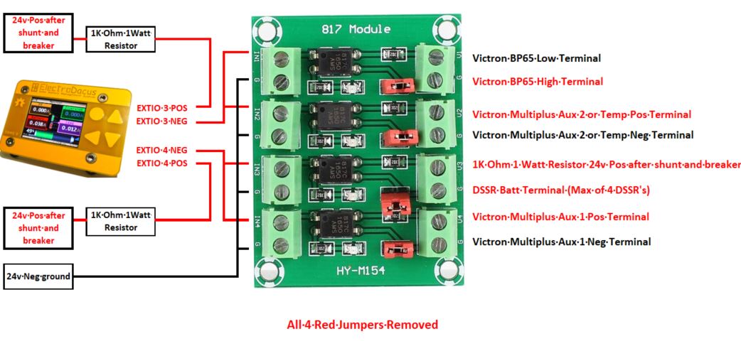
I set up the Optocoupler a few months ago. Dacian helped me with some of the design choices and it is working perfectly.

Dacian Todea
Feb 25, 2021, 12:12:18 PM2/25/21
to electrodacus
Richard,
Thanks for posting the diagram. The 1Kohm resistors seems to be supplied by a 16 AWG cable and that cable should have a properly rated fuse maybe 5A to be protected by a possible short and in that case it should also be before the 80/100A breaker as you will not want to lose both charging and load if that breaker ever gets disconnected for any reason.
Richard Bewza
Feb 25, 2021, 7:56:42 PM2/25/21
to electrodacus
Dacian,
Thank you for the feedback. I've placed all power consumers after the 80 and 300 amp breakers, as this fifth wheel will only be used occasionally. By turning off the these two breakers, the system goes into semi-hibernation mode with only SBMS0 and it's wifi module running. (no charging or discharging)
To enter full-hibernation mode I would then disconnect the balance cable from the SBMS0. In winter the fifth wheel may be covered for months at a time blocking the solar panels with no shore power close by.

Marinepower
Jan 26, 2022, 12:09:47 AM1/26/22
to electrodacus
Sorry to revive an old thread. These 817 optocuplers are a great add on for the SBMS if your loads only need 30ma or so, but as a lay person, I find them very confusing.
First, there seems to be a number of versions floating around Amazon which list their input signal max voltage differently. Some say (like the link below 3.3v - 5v. , but then say in the specs up to 24v signal is OK?) Are higher voltages permitted for these 817s, as long as you have a total of 1.5k Ohms resistance on the positive signal input (for a 12v system)?
On the load side, I assume these relays' load-side current should only flow in one direction ( like the Victron BatteryProtects) ? Where the positive goes in the load-side input labeled in the above diagram as "V1", "V2" . If this is correct, then the above diagram seems wrong. The Victron's "H"(High) term should go into "V1". No?
Can someone tell me if this is correct?
BTW: this is the 817 i just ordered.
Specification:
Item Type: 4-way Voltage Isolation Board
Guide gate signal voltage: 3.6-24V
Output Port Voltage Port: 3.6-30V
The jumper can reach the exit gate: high potential or pull the exit pad
Item Type: 4-way Voltage Isolation Board
Guide gate signal voltage: 3.6-24V
Output Port Voltage Port: 3.6-30V
The jumper can reach the exit gate: high potential or pull the exit pad
Not clear to me at all I have the right 817 version for my 12volt application. Any help would be appreciated.
MP
Message has been deleted
Dacian Todea
Jan 26, 2022, 3:39:56 PM1/26/22
to electrodacus
The optoisolators including 817 have an input and an output.
The input is nothing more than an infrared LED so about 1.2 to 1.3V drop at 10mA Since they already have a 3kOhm in series on the input if you apply 12V then you will have 12V -1.3V = 10.7V drop on the resistor so 10.7V / 3000Ohm = 3.56mA so sufficient to close circuit on the output. Adding a 1kOhm in series will reduce a bit that current but it will still be sufficient.
So voltage is irrelevant for input just the current is important you can even input 100V if you add a resistance enough to limit the current to less than 10mA.
On the output you will need to remove all those red jumpers before using.
Then you will connect the V1 to positive that in case of Victron means the "L" pin (I know is confusing as they mark that as L since if you connect that to GND you can turn ON the BatteryProtect and if you connect the "H" to 12V you can also turn it ON) but if you measure the L will have some positive voltage and H will have 0V so if you use both L and H then you will connect the L to V1 and H to G1 on those boards.
Marinepower
Jan 27, 2022, 3:06:03 PM1/27/22
to electrodacus
This is great. Thank you for the reply.
I was very confused by the signal voltage specifications. This makes sense to me now. As I already have a 470 ohm resister on the EXTO+, I wont put another in series for this 817 signal input.
Also, thank you for confirming that the load side is polarity sensitive. Current must flow in one direction only.
I have a couple HVC events I would like to control and each has different triggers. One is ignition-on dependant (alternator regulator) , one is shore charger dependant (DC-DC charger) and a third should always be on (Solar Charge Controller). These 817 boards are great for separating out this logic.
MP
Reply all
Reply to author
Forward
0 new messages