RV System Diagram for review
302 views
Skip to first unread message

DavidS
May 1, 2021, 7:48:39 PM5/1/21
to electrodacus
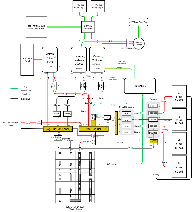
Details:
24v 3p8s Eve/Lishen battery bank
Electrodacus SBMS0 BMS
DSSR20's x 4
2x 24/3000 Victron Multiplus
1x Victron Orion 24/12 70a
Shore Power
8x 300w Solar in 2p config for the DSSR20's
3kW Dual fuel generator
240v Mini Split AC
24V compressor fridge
Goal: Create an electrical system that will allow me to stay 14 days straight at a CA state beach OR a CA desert dispersed camping site (think Alabama Hills) with no hookups. Water and dump stations are generally available, but there are no electrical hookups. I want full electrical living, including AC overnight, but I will avoid the very hottest months in the very hottest locations. Generally, I will get very good sun, given the location. Genset is strictly for backup, in the event of crappy sun.
I'm removing the 6kW Onan Diesel genset from my 37' Super C RV and replacing it with a fully inverted system. I'm removing the roof mounted A/C's and replacing them with the mini split. I'm updating the existing propane/120v ac evap fridge with a 24v compressor unit and I'm removing the propane heater in favor of a diesel heater + heat pumps in the mini-split. Mini-split is a 240v ac unit, 30kW dual zone and I'll be replacing the existing AC units with new Maxxair fans. Phase 2 might include diversion heating via the DSSR's for hot water. Primary control will be via SBMS0, with a Home Assistant installation + Mosquitto MQTT to intake info and display a dashboard. Also currently working on a Mikrotik cellular booster for LTE & 5G. So much fun...

Dacian Todea
May 1, 2021, 8:19:24 PM5/1/21
to electrodacus
David,
- You can not have a fuse between the battery shunt and PV shunt the two shunts will need to be connected directly with nothing in between them and you can add that fuse between the shunt and the positive bus bar.
- Those panels will put out 80 to 90A so the 6AWG may not be quite enough depending on the type of cable on the negative side also the PV shunt will need to be at least 150A rated as shunts can only handle around 66% of rating continues. Same comment about what looks like a 80A fuse after all PV panels are combined.
- The two switches for the inverters can be on the positive side (no reason to be on the negative but it will work the same) and before you are able to close circuit those switches you will need to precharge the inverter capacitors else you will damage those switches. Same thing with the DPST switch you need to precharge everything before being able to turn those ON.
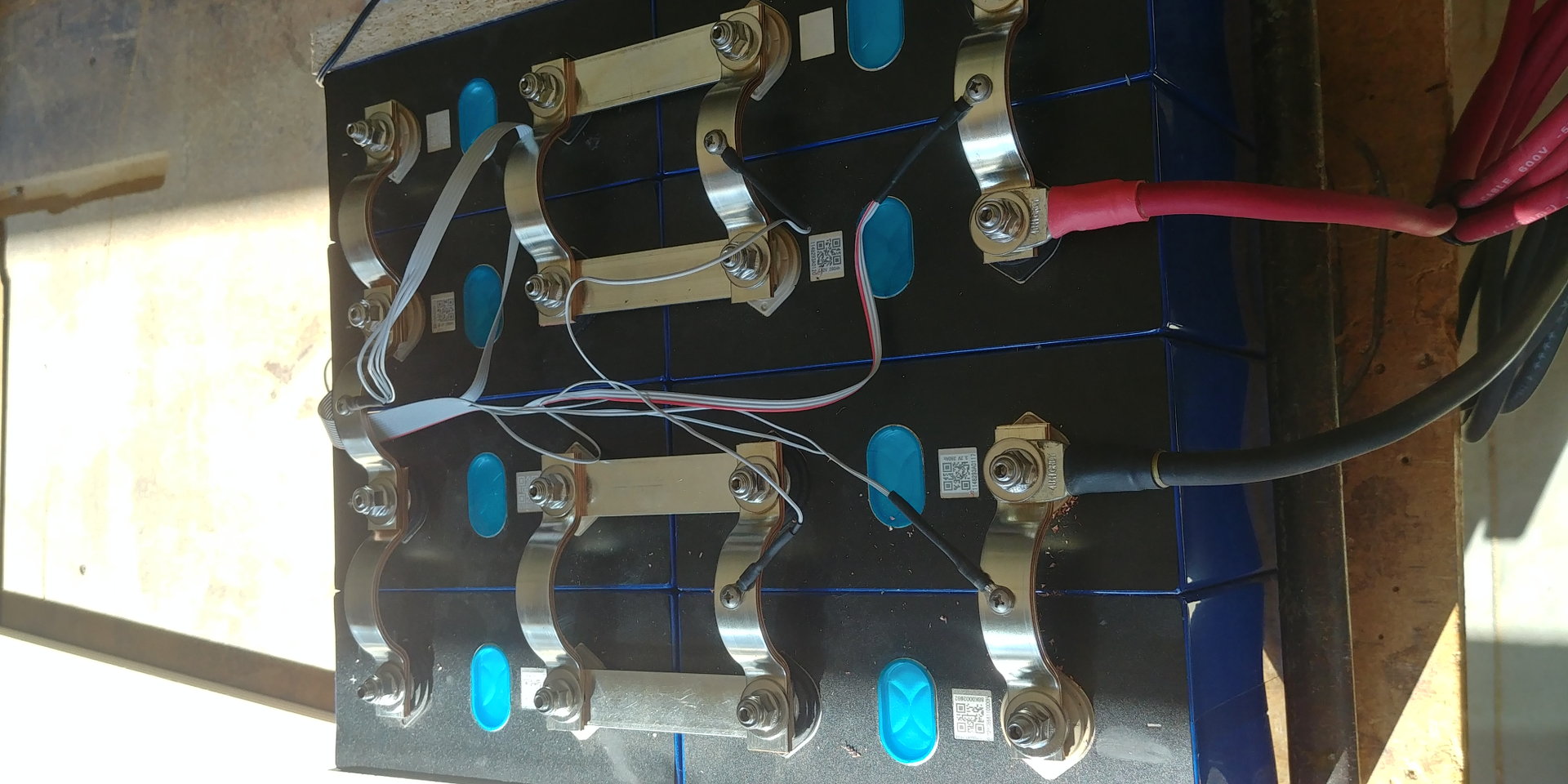
- The batteries because you presumably will have high loads should be installed in a different orientation so that 3 parallel buss bars caries the current instead of just one. Below is an example that is just 4s2p but the concept is the same. There is still a single busbar between cells 2 and 3 in that photo but in that particular case he did not had such high loads like you will have.
-There is also a general thing that you have all sorts of fuses and breakers close to load instead of close to the busbar. Like those 300A fuses for the inverters should be just immediately after the Load busbar as what you protect is the wires and so need to be close to the source (battery) that is an unlimited current source.
DavidS
May 2, 2021, 1:59:15 AM5/2/21
to electrodacus
Dacian,
thank you for the guidance. I'll go back and make updates based on your feedback.

SolarChain
May 2, 2021, 2:14:39 PM5/2/21
to electrodacus
You might want to include your Non-functional System requirements. These would be how, as a user you want to operate the components, failover/fault tolerance etc and of course testing out those requirements. This becomes a big part of these designs and is often overlooked. I like your overall high level functional requirements as you looked at it from a capacity/use case perspective when boondocking.
Dacian Todea
May 8, 2021, 7:28:31 PM5/8/21
to electrodacus
David,
All seems to look fine I'm just not sure the 100A GFP will not trip in some situations as you have 8 x 305W panels and they will in normal conditions put out around 11A each and there may be situation where they will exceed 12 even 13A for some seconds and those breakers should be OK with 100% load no trip but amient of +25C not sure how it will look like at higher ambient temperature.
Also not sure why ground fault protection will be necessary in this system that is more useful maybe for higher voltage PV arrays. Of course using a GFP breaker will have no negative impact but is extra money for a function I do not think is needed.
DavidS
May 9, 2021, 1:56:25 AM5/9/21
to electrodacus
Thanks Dacian. It's definitely worth considering. I'm looking to ensure that I create the safest installation reasonable and to comply with the NEC where I can for insurance purposes. In the end, I may leave the GFP breaker out if it becomes problematic.
I really appreciate you taking the time to respond in such detail.
Reply all
Reply to author
Forward
0 new messages