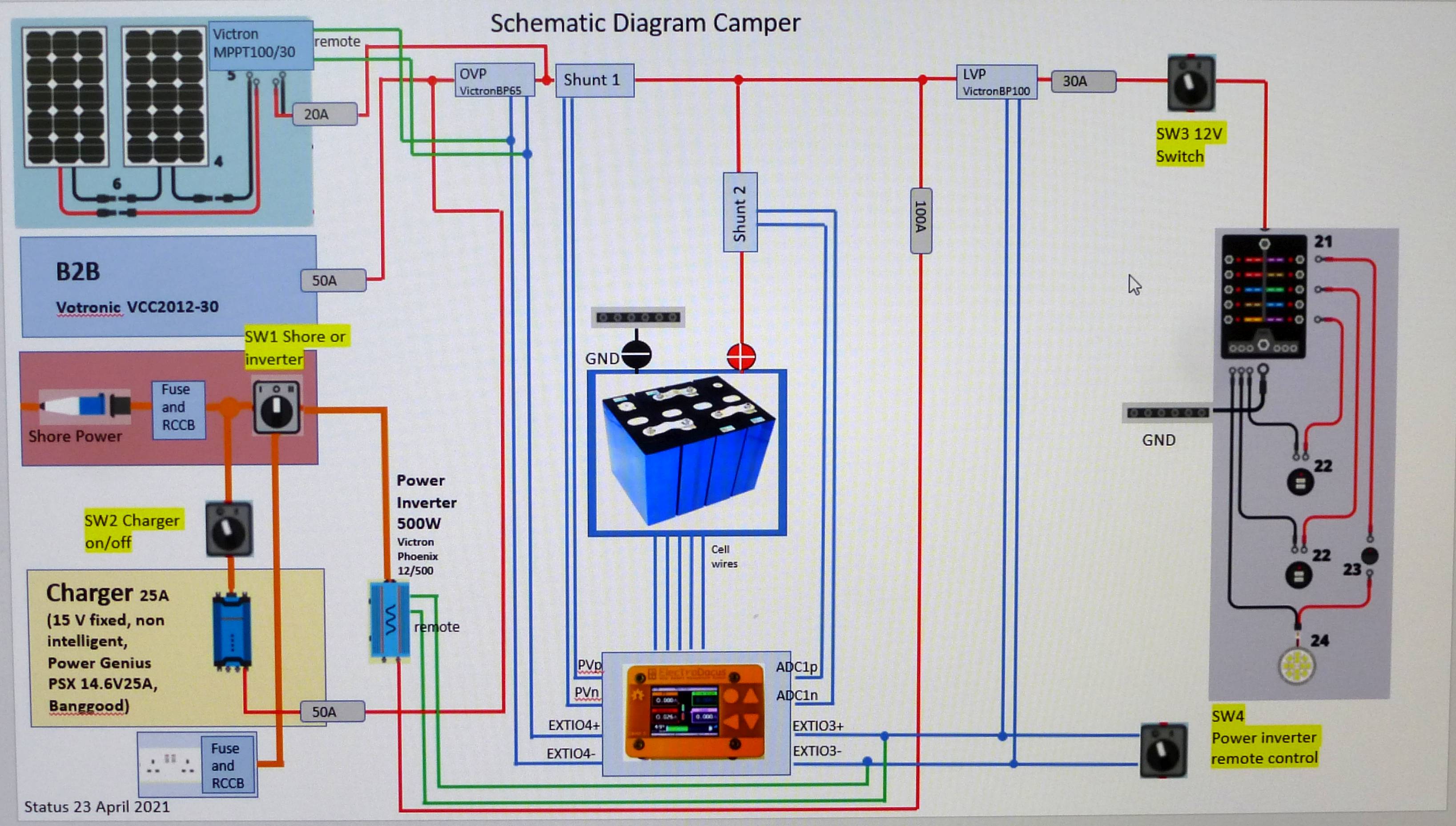
wiring schematic for a Camper Van
180 views
Skip to first unread message

Dietmar Miller
May 1, 2021, 10:40:58 AM5/1/21
to electrodacus
I want to install the electrics for my Ducato Camper van. I made a schematic for it. it is my first campervan and I do not have any experience. I have all the components except the solar panels. one question I have is the battery charger. I was told that I cannot run it parallelly to the MPPT because it could destroy the charger. Therefore I made a switch which either connects the MPPT or the charger to the battery. Is there a better way I can do it? is there a possibility that the charger is simultaneously loading with the MPPT?
do you have any recommendations for my schematic based on your experience (Fuses, switches etc)?
thanks, Dietmar

Dacian Todea
May 1, 2021, 1:49:59 PM5/1/21
to electrodacus
Dietmar,
You can use both MPPT and the grid charger at the same time but then the MPPT should be connected after the BP65 so to shunt 1 in your diagram and of course then you need the MPPT to be controlled using this remote ON/OFF cable https://www.victronenergy.com/accessories/ve-direct-non-inverting-remote-on-off-cable

Jake
May 1, 2021, 4:57:26 PM5/1/21
to electrodacus
Nice diagram - just one thing on the inverter/battery protect:
Vitron does not recommend using the battery protect to turn on/off an inverter (BP100 in your diagram). The high inrush current of the inverters capacitors can damage the battery protect.
Instead move your BP100 to where your 30A fuse is, and use the EXTIO3 to turn the Victron Phoenix on and off using it's remote port. I think you can run two sets of wires from EXTIO3, one to the BP100 and one to the inverter to control both.
Jake
May 2, 2021, 11:32:05 AM5/2/21
to electrodacus
Looks good. I've been thinking about how to turn the inverter on and off independent of the SBMS in my system as well.
Since the EXTIO3 is creating a short circuit when it's "on", then if I wanted to manually turn off the inverter while it's not in use, I think a SPST switch (SW4 on your diagram) on just the EXTIO3 positive line (green in your diagram) would function as a manual off for the inverter.
It has the added benefit of not being able to turn the inverter on if the SBMS detects an undervoltage condition (empty battery).
The SW3 switch should work as-is, but it could also be on the EXTIO3 positive line (blue) going to the BP100
The charger should also work fine, but if you wanted something silent, check out MeanWell's LED drivers. Adjustable voltage, fully potted, and no fans.
Two questions:
What is the B2B Votronic device? If it's a way to charge your Lifepo4 off the engine's alternator take a look at Renogy's DCC50S, it combines the MPPT with a DC-DC charger, but there is nothing wrong with your current setup.
What software did you use to create this diagram? Looks nice!
Jake
Dacian Todea
May 2, 2021, 2:05:37 PM5/2/21
to electrodacus
Dietmar,
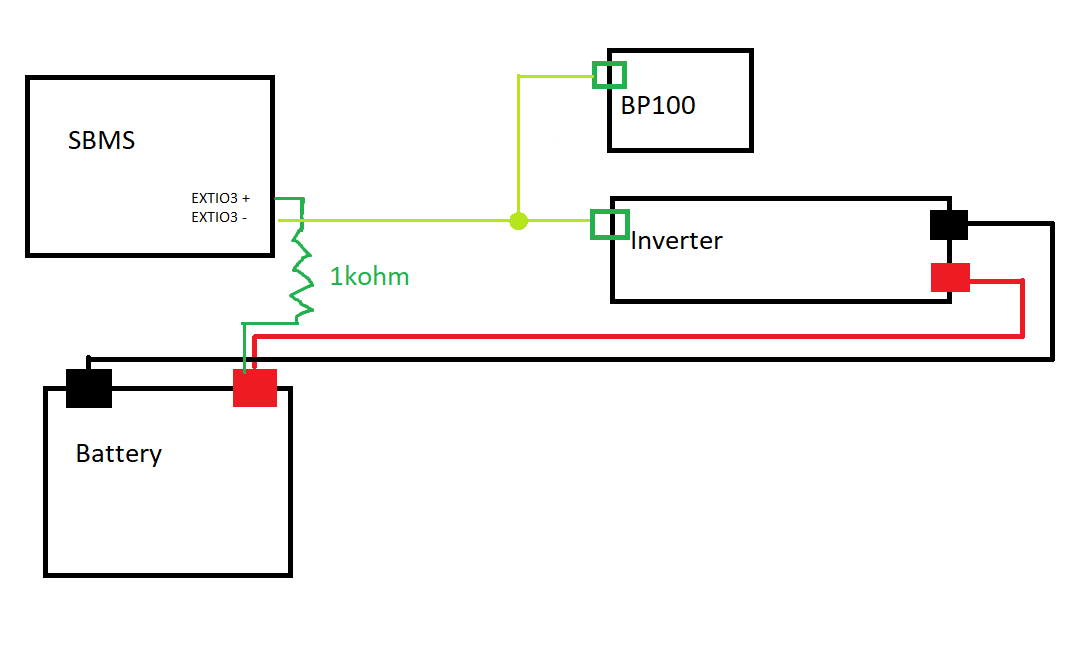
Yes it looks OK just not sure if the Phoenix inverter and BP100 remote can be paralleled (you can try) but it will work for sure if you connect EXT IO3+ through a 1KOhm resistor to battery+ and then EXT IO3- connected to H connection on both BP100 and inverter and that will work for sure.
Jake,
Yes adding a switch in series with the remote wire can allow you to manually turn OFF any device including an inverter.
Jake
May 2, 2021, 2:30:56 PM5/2/21
to electrodacus
Dacian,
I'm probably missing something, but is this what you mean?
Dacian Todea
May 2, 2021, 2:37:16 PM5/2/21
to electrodacus
Jake,
Yes that is what I mean just need to make sure you connect to the connection point noted as H on the remote ON/OFF connector.
Reply all
Reply to author
Forward
0 new messages