Beginner's Guide to ElectroDacus v0.5
1,363 views
Skip to first unread message

Oberon Robinson
Mar 25, 2021, 3:05:33 AM3/25/21
to electrodacus
New version of the Beginner's Guide is attached. As always, comments, suggestions, and corrections are very welcome.
One thing I'm still not 100% on is if all of the EXTIO types are normally-closed. Or does Type 5 close under a fault condition?

Dacian Todea
Mar 25, 2021, 2:16:33 PM3/25/21
to electrodacus
Oberon,
All EXT IOx are normally open meaning that is the SBMS0 is not powered they are all normal open (they are based on Toshiba TLP187 for the older SBMS0 version and TLP172GM for the new SBMS0 v03d). This is the only safe option as if something happens with the SBMS0 (power lost) or if any of the EXT IOx wires is broken (open circuit) then whatever those controls will default to OFF so safe.
What you maybe ask is that when everything is normal and charge and or discharge is enabled then those corresponding EXT IOx set as type 1 or 2 will be close circuit so charger will be ON and loads will be ON
In case of type 5 is the same if there are no errors like Overvoltage Lock / UnderVoltage Lock then the EXT IOx set as type 5 will be close circuit so if either under voltage lock or overvoltage lock flag is set the EXT IOx set as type 5 will become open circuit same will happen if one of the two EXT IOx wires is broken or if SBMS has no power (say 12pin cell monitoring is removed).
So if you want to use a shunt trip circuit breaker you will need to add a normally closed SSR (there are a few options for that) and then the input of that will be supplied by the EXT IOx set as type 5 thus as long as EXT IOx as type 5 is close circuit the SSR will be open circuit meaning the shunt trip breaker coil will receive no power thus breaker will be close circuit and if EXT IOx becomes open circuit from any reason (over or under voltage lock flags) or the EXT IOx wires become broken then the SSR since is a normally closed one will power the trip coil and the breaker will become open circuit.
Oberon Robinson
Mar 25, 2021, 6:54:05 PM3/25/21
to electrodacus
Got it, thank you. I meant to type normally-open, I guess my brain was tired! :)
Oberon Robinson
Apr 2, 2021, 12:50:40 PM4/2/21
to electrodacus
Dacian, will you ever be making any more of the DMPPT thermal controllers? Or does the DSSR20 diversion replace its functionality? I didn't include it in the Beginner's Guide but I did make a reference to it in the Overview.
I'm also hoping that you can find a 1/2 hour sometime to read through the guide and correct me on any errors, then you might like to make it available on the ElectroDacus home page - I'm pretty sure it will greatly help reduce the amount of time you need to spend responding to support requests!
Dacian Todea
Apr 2, 2021, 1:48:31 PM4/2/21
to electrodacus
No plans to build the DMPPT450 but there is a small chance there will be a modular DMPPT100 if there is demand for that. The DSSR20 has a small part of the functionality in therms of diversion but that is not digital MPPT.
I'm super stressed at the moment as I'm close to running out of stock on many devices and need to produce more and also order a lot of components. It seems there is a shortage for all sort of electronics parts shiping gets more and more expensive.
Probably this week I will no longer have the DSSR20 without diversion only the one with diversion and that will be produced and available for likely this year based on current stock I have then it will be replaced with a DSSR50 (need to finalize the prototype design to have the PCB done and properly test that). Main reason for not producing the DSSR20 is that connectors are no longer available (they sort of are but at 3x higher price than originally and it will start not be be economical because of that). I do not want to provide much info on the DSSR50 as it is still in early design stage and things may change. But I will provide a bit more data once the first prototype is ready and tested. Initially that DSSR50 will not have diversion and diversion will be available as a separate device latter in this year so the DSSR20 with diversion will still be the available solution until then.
The DSSR50 and whatever the diversion option for that will be called can then be part of the modular DMPPT100 if there will be demand for that. I designed the DSSR50 with the DMPPT100 idea in mind so it was designed to be used that way but I'm not sure if it will be worth investing my time in to the DMPPT100 as that will require not just hardware design but also a lot of software and testing.
I will need at least a half day to look through your document and not sure when I will find the time. Hopefully other will read it in the meantime and they can point out what needs to be changed. I know I started reading the first page initially and it will have been to much comment to be made just there maybe equivalent to this replay here for just the first page.
Oberon Robinson
Apr 2, 2021, 2:19:38 PM4/2/21
to electrodacus
Sorry to hear that you're so stressed - hopefully as the covid vaccine gets more and more widespread it will reduce all of the shortages we're seeing everywhere, and things will start to flow more smoothly again. Not sure if prices will go down much though!
A lot of smart and highly-qualified people have looked over the guide and given me good feedback, which has improved it a lot, as well as given me a great learning process. Of course, nobody else has your depth of knowledge on all the inner workings. Anyway lots of people have said that it was very helpful to them, so hopefully it will continue to cut down on your support time.
I'm happy to hear that there is at least a chance of a DMPPT100. I don't have a use case for it for my current van build, but I'm hoping to build a new passive house sometime in the next couple of years. I'd love to include DMPPT in the design.

Jhon
Apr 2, 2021, 8:24:57 PM4/2/21
to electrodacus
Guide is looking great, thought I provide some feedback, from the perspective of this newbie. (I usually don't like doing this as it can be perceived as something like telling a mother her baby is ugly, so let me say it again, it really looks great)
Instead of using Isc? use the full name, it makes it easier to read, but lengthier. On a side note, om my screen the "sc" part is really small and my eyes are not what they used to be.
In section 5.2 my eye was drawn to the relay board, you might want to put the description for it as the first discription and/or provide images for the other parts.
In section 5.4 you write "If you use one for this purpose" you might want to replace "one" with "Victron Battery Protect" to make it clear for the reader that is what you meant.
In section 7 you use the term "ampacity", I think that is a word more common in the US, it is certainly new to me, maybe "current rating of the wire" would be a better choice and keeps the terminology consistent with the other items, like fuses and circuit breakers?
In section 7.3 needs some work. Explain why automotive fuses are not a good idea with lithium (I never thought about it myself until just now and I am quite interested as well) Maybe reword the "Your inverter will need its own DC fuse on the supply side" with something like "Pay special attention to wiring the inverter, the DC cable between the battery and the inverter needs to be sized and fused appropriately." And replace "and an AC breaker box on its load side" with something like, "connect the AC from the inverter to a seperate AC switch panel and from there to the outlets." Not sure how to word it myself either to be honest.
In section 7.4 replace "If there won’t be a resistor in the circuit, then they should have a fuse instead." with "If there isn’t a resistor in the circuit, you should use a fuse."
in section 8.3, you might want to point out that the SBMS0 put the shunt(s) on the positive side, while most BMS's use the negative, so it can confuse people. (There can be a short wire between the shunt and the battery, just no fuse or circuit breaker as I think that disconnecting the positive can damage the SBMS0)
In section 8.6 "If you aren’t using a PV shunt, set ‘PV1 shunt On/Off’ to 0. " I believe 0 (off) is the default and needs to be turned on. (I spend hours looking for that problem last month)
The problem is that the more we read those documents, the harder it is to look at it from the perspective of a newbie, so I hope you can use some of this. Again thank you for writing it, I am sure many people, including myself, will find it very useful.
Oberon Robinson
Apr 2, 2021, 8:33:38 PM4/2/21
to electrodacus
Thanks very much, Jhon, that's all great feedback! I appreciate you spending the time to go through it and write up your notes on everything -- I'll incorporate them all in the next version. And don't worry about it being an ugly baby, all babies are ugly when they're newborn!
Jhon
Apr 2, 2021, 8:43:10 PM4/2/21
to electrodacus
Sorry to see you are stressed, and after reading it, I added to your stress by ordering another 4 DSSR20's before you run out, I like to keep the design simple. I already bought another 8 panels (they only had 11 left in stock) and will double my battery capacity when the suppliers in China can get the 272 Lishen cells back in stock.
You have made some impressive products Dacian, I love open source, even though I can't build it and this system is perfect for my needs. My only suggestion is to make it more fault tolerant as people like me can and do make mistakes, like forgetting to unplug the sensing wires, or do something that seems logical, like putting a fuse between the shunt and the battery. I know you can't make it idiot proof as the world will only invent a bigger idiot, but still...
You have made some impressive products Dacian, I love open source, even though I can't build it and this system is perfect for my needs. My only suggestion is to make it more fault tolerant as people like me can and do make mistakes, like forgetting to unplug the sensing wires, or do something that seems logical, like putting a fuse between the shunt and the battery. I know you can't make it idiot proof as the world will only invent a bigger idiot, but still...
On Friday, 2 April 2021 at 13:48:31 UTC-4 electr...@gmail.com wrote:

Don Fukushima
Apr 3, 2021, 1:07:34 PM4/3/21
to electrodacus
Oberon,
This is an excellent document covering so much detail in one place. I also recognize the contributions of other, as you have, and brought it all together into one place. As Electrodacus products are new to me, less than a year, and finally getting it mostly sorted out, my ability to contribute to any technical review is limited. But from noobie eyes it would be an excellent document for someone starting with this.
One suggestion 8.7 sent calibration. You do state calibration occurs during power up but I think it helps to make that more clear and bold. Often times, especially while getting it all going, the device is powered of and on for various reasons and one must be aware to disconnect all power draining before reconnecting the SBMS0; otherwise, the current numbers are not correct, and for noobie, it can be confusing, leading to thinking something is wrong when all that is needed is to make sure there is no draw on system. There is mention in 11.7 but again, sort of mentioned as not so critical, just make sure it is very clear to do this of suffer effects.
11.7 date time - make mention that these settings get lost after SBMS0 loses power and must be reset and saved.
EXTIOx SOC values. It does say used for type 3/4 but maybe make more clear that for most use with DSSR20, just ignore the numbers. It caused ,e much questioning what to set the value when it should be ignored in this case.
Where you provide links to suggested parts, include some specification so if link dies or someone wants other source, there is enough spec to do so.
The last thing of worry for me now is what happens when SBMS0 fails. Is the rest of the system protected. On the PV side, the DSSR20 default to disconnect so no worry about overcharge of battery. On the drain side, the inverter has circuitry to shutdown on low voltage. Other devices connected to battery with no low voltage cutoff can kill the battery. Now, this is not a SBMS0 issue directly but since you show wonderful system wide schematics, it is something one should consider as failsafe for battery protection. In your diagrams, something where the black busbar connected to battery would be likely place for a relay that disconnects when zero power and that could connect to an EXTIOx.
Dacian Todea
Apr 3, 2021, 1:32:17 PM4/3/21
to electrodacus
Don,
Something is wrong if the calibration during power ON in not correct and that I why I do not insist in explaining much about the power ON calibration as at least people will ask about why that is not correct and then be able to find out that they installed the system incorrectly.
If SBMS0 is installed correctly meaning SBMS0 has remote ON/OFF for all charge sources and all Loads then zero current offset calibration will be done correctly as during power UP sequence the SBMS0 will keep the charge sources and Loads OFF so current calibration will be done correctly. But if any of the Loads or charge sources is not connected to SBMS0 remote ON/OFF (EXT IOx) then SBMS0 can not turn that OFF and so current indication will be wrong as zero offset calibration will be done wrong.
There are many way the SBMS0 can possibly fail but if all is installed correctly all loads and all charge sources should be OFF. The remote ON/OFF done trough EXT IOx are optically isolated so if say SBMS0 loses power completely for any reason like internal fault of just removed 12pin cell monitoring connector then all Loads and charger sources will be OFF if installed correctly.
The fail safe can be a circuit breaker with trip shunt controlled by the EXT IOx set as type 5 then if for some reason one of the Loads or charge sources fails to respond to the remote ON/OFF and any cell exceeds either over or under voltage lock thresholds (secondary level thresholds) then type 5 will become open circuit and that will trip that circuit breaker that should have at least two separate contacts that way both the charge sources and separately Loads can be disconnected and keep separate the charge sources from Loads so that charge sources will not damage the Loads since both will remain without a battery.
So this fail safe if needed will be installed immediately after the PV current shunt and battery current shunt respectively that way isolating the battery from all charge sources and separately from all Loads.
There is a post I made recently showing some trip shunt breakers for this sort of application.
This is one of the reason that I think best option for those not very technical is not a guide or user manual but a set of complete examples to select from having full schematic/diagram and all the parts list needed to build the example that way making sure that all will work as intended. I just do not have the time at the moment to do that.
Oberon Robinson
Apr 3, 2021, 1:59:14 PM4/3/21
to electrodacus
Thanks very much for your feedback, Don
— I really appreciate everyone who reads through and suggests areas that need more clarification.
Dacian, I have to respectfully disagree that non-technical people don't want to have a more full understanding of the system. From what I've seen reading through a lot of solar forums, the type of person who builds a DIY system wants to understand everything that they are doing, and learning it is part of the pleasure of DIY. People who aren't interested in understanding at least some of the technical details will just buy a complete drop-in system, or hire a professional installer. The target market for ElectroDacus is very much the DIY community, and that type of person wants to know the WHY, not just the HOW. I still think it would be great to have your set of complete examples, whenever you are able to find the time to put it together. But I've also had a large number of people tell me how helpful the Beginner's Guide has been for them as well. I always think that more documentation is better!
Dacian Todea
Apr 3, 2021, 2:07:10 PM4/3/21
to electrodacus
Oberon,
The problem is that people will understand just that part and so bypass the safety by manually turning off say the inverter so that zero offset current is done correctly not understanding that remote ON/OFF is mandatory and then ending up with a damaged battery as inverter under voltage protection can not protect the battery at all.
Most inverters undervoltage is set at 10.5V or so then it will be most likely 3 of the 4 cells will be at 3V and one of the cells the one with just slightly lower capacity will be at 1.5V and be damaged. Same with 24V system or a charge source that has no remote ON/OFF control and battery is overcharged.
If all is installed correctly then you do not need to care about the zero offset current calibration as it is done automatically and will be done correctly as the SBMS0 can turn off all Loads and charge sources during power up sequence.
Don Fukushima
Apr 12, 2021, 7:18:56 PM4/12/21
to electrodacus
Hi Oberon,
 alue that
I have a suggestion for the guide in section 5.5 EXTIO types.
What has caused confusion is how the %number on the right is used. The scrolling message is was not enough for me but after some searching around, I believe enough details were found to understand it.
My case is similar to the default where EXT IO4 is used to control the battery charging circuit. Adding an explanation would help to know just what gets affected based on that percentage number. It acts differently based on the Type value and from what I read, it may be monitoring battery SOC or maybe battery voltage.
thanks
alue that On Thursday, March 25, 2021 at 12:05:33 AM UTC-7 Oberon Robinson wrote:
Oberon Robinson
Apr 12, 2021, 7:34:38 PM4/12/21
to electrodacus
Don, if I understand correctly, the SOC % setting only applies to Type 3 or 4 EXTIO types.
I'll add some more explanation in that section. Thanks for the feedback!
Oberon

Center Right Proud American
Apr 12, 2021, 8:08:19 PM4/12/21
to electrodacus
I would like to see Dacian weigh in on this. I used to think like Oberon but now I am not so sure. I was going through the manual over the weekend (for other reasons) and came accross a couple of things that made me question how it worked. Each time I read them I come away with a different conclusion.
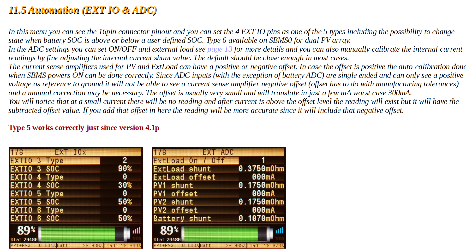
11.5 Automation (EXT IO & ADC)
In this menu you can see the 16pin connector pinout and you can set the 4 EXT IO pins as one of the 5 types including the possibility to change
In the first photo you can see the same two DMPPT450 settings max charge current and Max SOC also
apply now to SBMS0 directly.
The max SOC limit is in this example set at 70% and what will happen is that every new day the battery will
first be fully charged 100% SOC but then the next charge cycles for the same day will only start at 67% and
end at 70% so it will stay around 70% SOC and cycle there with a 3% SOC hysteresis. You can set this at
any limit 80 to 90% will be great setting for LiFePO4 while for NMC and LiCoO2 around 70% to 80% will be
11.5 Automation (EXT IO & ADC)
In this menu you can see the 16pin connector pinout and you can set the 4 EXT IO pins as one of the 5 types including the possibility to change
state when battery SOC is above or below a user defined SOC. Type 6 available on SBMS0 for dual PV array.
8 Dual PV array functionality and SOC charge limiting
SBMS0 has now to of the DMPPT450 functionalities see below the details.In the first photo you can see the same two DMPPT450 settings max charge current and Max SOC also
apply now to SBMS0 directly.
The max SOC limit is in this example set at 70% and what will happen is that every new day the battery will
first be fully charged 100% SOC but then the next charge cycles for the same day will only start at 67% and
end at 70% so it will stay around 70% SOC and cycle there with a 3% SOC hysteresis. You can set this at
any limit 80 to 90% will be great setting for LiFePO4 while for NMC and LiCoO2 around 70% to 80% will be
best.
It makes it sound like the output will turn on on *either* voltage or SOC....... but it is not clear to me if the %SOC only apply if you are using type 3 and 4 or if they would also apply on a system only using type 1 & 2
Don Fukushima
Apr 12, 2021, 8:15:48 PM4/12/21
to electrodacus
The reason I posted was I thought like that too until I was actually monitoring system and watched it behave a different way than the docs.
So, today bank shows 53%, voltage getting to full setting, then SBMS0 decides full so reading is 100. Then big load on system and getting past prime time for gathering solar and getting worried how low it'll get drained as the SBMS0 is not switching on the DSSR20. 95-90-89-88-87 then DSSR20 switches on and PV start charging again.
More reading said that is how SBMS0 know when to start charging again once it was full and being used.
That scrolling message is misleading and confusing to me at least so it seems good to explain it better in the doc.
Dacian Todea
Apr 12, 2021, 8:18:40 PM4/12/21
to electrodacus
As Oberon already mentioned the SOC only has an effect on type 3 and type 4 that normally you will not use for anything other than maybe an alarm.
There is the DMPPT menu that contains an SOC setting is a different story and applies to type 1 (or type 1 + type 6 in case of dual PV array).
The SOC setting in the DMPPT setting menu will be in effect only after the first full charge of the day so first charge is always done to 100% based on cell voltage 3.55V default for LiFePO4 and from there if SOC is set lower than 99% it will work within that limit for the remainder of the day with that 3% hysteresis mentioned in the example.
Don Fukushima
Apr 12, 2021, 8:27:59 PM4/12/21
to electrodacus
I am again confused, sorry.
If setting EXT IO 4 to TYPE 1 and that wire goes to DSSR20, doesn't the number on EXT IO4 SOC row set the condition when SBMS0 turns on that IO port, in this case, turn on DSSR20 and starts the charging cycle?
Dacian Todea
Apr 12, 2021, 9:07:19 PM4/12/21
to electrodacus
Don,
The SOC number under EXT IO4 has no meaning for type 1 (meaning it will have no effect).
Oberon Robinson
Apr 12, 2021, 9:17:54 PM4/12/21
to electrodacus
Don, to hopefully clarify a bit more, a Type 1 EXTIO will switch on and off based on the cell voltage settings under Advanced Parameters. After the daily full charge, it will also keep it to the 'Max SOC' setting under DMPPT.
Dacian, one thing I don't fully understand is the difference between 'Over Voltage' and 'End of Charge' in the Advanced Parameters. I get that the 'Over Voltage' has a time delay and the 'End of Charge' does not, but I would have thought that the time-delayed voltage would be slightly lower by default, and it's slightly higher.
Dacian Todea
Apr 12, 2021, 9:47:48 PM4/12/21
to electrodacus
Oberon,
The End Of Charge has no real effect or meaning in regards to charging. Over voltage is the limit you want to charge the battery and yes that has a delay that needs to be higher than the cell balancing ON time at least by one second so that the cell voltage reading during cell balancing ON have no influence on the Over voltage limit.
Center Right Proud American
Apr 12, 2021, 9:49:53 PM4/12/21
to electrodacus
>
Type 1 EXTIO will switch on and off based on the cell voltage settings
> under Advanced Parameters. After the daily full charge, it will also
keep
> it to the 'Max SOC' setting under DMPPT.
OK....I *think* I am starting to understand. However, since SOC is set in various screens..... I want to make sure I have it right.
On page 38 of the SBMS0 manual, there is an image of the screen "1/8 EXT IOx". In the image there are two rows for EXTIO3:
EXTIO 3 Type ------------- 2
EXTIO 3 SOC ------------- 90%
In this example, since EXTIO 3 Type is 2, the EXTIO 3 SOC setting is ignored.
However, On page 39 of the manual there is an image of the screen "1/6 DMPPT Settings". In the image, there is a row that says:
Max SOC -------------90%
Max SOC -------------90%
What that setting means is that on a system that is using type Type 2 to charge , the system will charge the batteries to 100% at the beginning of the day and then only charge the batteries enough to keep them at the 90% SOC that is set on the DMPPT page.
Do I have this correct?
Dacian Todea
Apr 12, 2021, 10:03:19 PM4/12/21
to electrodacus
Yes SOC is ignored for type 2. Maybe I should grey out the SOC setting for types other than 3 and 4 where they have an effect is just some extra work. Also type 3 and 4 is not something I ever recommend as SOC may be wrongly calculated if installation if settings or installation are not done correctly and in case of charging especially is a very bad idea to stop charging at a certain SOC level and never have a full charge as SOC errors will quickly add up (with no correction to full charge) and so you may end up with a battery that shows 80% SOC but real SOC is just 10%
Type 3 and 4 where designed for alarms or special automation when you have multiple charge sources and you know what you're doing.
Regarding page 39.
Yes but be careful for charging you will use type 1 (type 2 is for Loads) and the battery will always be fully charged to 100% then for the remainder of the day (based on SBMS set clock time with reset at midnight) and then after the full charge at 100% the charging will be disabled until SOC drops below 87% then stop when it gets 90% and will cycle there probably a few times until midnight.
If that SOC is set at 99% as it is by default then SOC is ignored and battery is always charged to 100% based on voltage so charging will stop at 3.55V and then start when all cells drop below 3.4V.
Center Right Proud American
Apr 12, 2021, 10:12:59 PM4/12/21
to electrodacus
>
Yes but be careful for charging you will use type 1 (type 2 is for Loads)
Oops.... I got that backwards. Sorry for any confusion.

Chris Card
Apr 13, 2021, 12:58:17 AM4/13/21
to electrodacus
Oberon,
“End of charge” is the setting for the voltage at which the SOC meter goes to 100%. “Over voltage” is the set point for when charging ends.
Dacian Todea
Apr 13, 2021, 1:06:31 PM4/13/21
to electrodacus
Chris,
That is not the case. Both the End of Charge and Overvoltage flags need to be set in order for the SOC to be set to 100%.
Don Fukushima
Apr 13, 2021, 1:23:21 PM4/13/21
to electrodacus
Man, I am really feeling dumber by the day. Hopefully, this explanation is correct when using EXT IO port to control DSSR20 for PV load.
The SBMS0 EXT IO menu sets the IO port to control the DSSR20. The selected IO port is set to TYPE 1 to control the incoming load from the PV. SOC on the following line is NOT used with this type.
The first daily charge event charges the battery to the over voltage value set on the Parameters Settings-advanced settings page 1.
End of charge voltage value set on advanced settings page 2 is used to stop charging on subsequent charge cycles during the same day.
After the first full charge up, the EXTIO port assigned as type 1 and connected to the DSSR20 is controlled by the SOC value in the DMPPT menu screen. 99% is used to always keep the battery charged at 100%. A lower value lets the battery run down to that value then starts charging again when another 3% drop in SOC and stops at the defined value. The effect is the battery is then maintained between n and n-3 percent.
If this is right, then maybe Oberon can reword to explain this better for readers of the guide because even now looking over what is actually involved in managing the charging logic is not at all clear as related settings are on different screens and dependent on others.
Chris Card
Apr 13, 2021, 1:34:12 PM4/13/21
to electrodacus
Thanks for the correction Dacian, I had not realised that.
Oberon Robinson
Apr 13, 2021, 2:03:04 PM4/13/21
to electrodacus
What is the actual purpose of the End of Charge voltage setting?
Dacian Todea
Apr 13, 2021, 2:11:50 PM4/13/21
to electrodacus
Don,
PV solar is a charge source not sure why you refer to it as a load.
EXT IO4 is by default set as type 1 and usually the one used to control DSSR20
First daily charge is done to 100% SOC that means charging will stop when any cell gets to 3.55V (Over voltage) for more than 6s (Over Voltage delay) the End of charge is default set 2mV less than Over voltage 3.53V but will not affect the charing in any way.
After first full charge if the SOC in the DMPPT settings is set to default 99% the battery will restart charging when voltage of all cells drops below 3.4V (Over Voltage recovery) and charging will again be done to 100% so up to 3.55V
If that SOC in DMPPT settings is set any other value lower than 99% then subsequent charging will be limited to that value. Say SOC is set at 90% in the DMPPT settings menu then all charge cycles after first full charge will start at 87% and stop at 90%
The DMPPT setting screen is available on all SBMS models since SBMS40 / SBMS120 and it was designed for the DMPPT450 that is no longer available but some people still use that so I can not remove that menu and since that menu is there I use the same SOC setting to add this future to the SBMS0. The other SBMS models can not use this functionality of restricting subsequent charging to a SOC limit unless they use together with DMPPT450.
Oberon,
The End of Charge settings is used internally by the ILS94203 but it has no effect on charge or discharge FET so SBMS uses that mostly as a flag confirming the settings are correct and only resetting the SOC to 100% if both EOC flag and OV flag are set.
Oberon Robinson
Apr 13, 2021, 2:50:46 PM4/13/21
to electrodacus
Thanks Dacian. I'll add this into the next version of the Beginner's Guide.

Greg Kowieski
May 26, 2021, 6:46:27 AM5/26/21
to electrodacus
Oberon, I think I've read somewhere that you anchored the guide in the cloud somewhere. Git? maybe? Anyway, if you have, would you mind passing the link?
Oberon Robinson
May 26, 2021, 12:39:34 PM5/26/21
to electrodacus
Hi Greg, I couldn't find a good way to host it online that would preserve formatting, cross-references, etc. I did put a copy here: https://diysolarforum.com/resources/beginners-guide-to-electrodacus.174/ Nice to see it's been downloaded 250 times from that location.
I have a new update in the works but haven't had time lately to get it finished. There's a new section on mobile considerations, since that seems to be a popular application for ElectroDacus. And I've added more specifics about shunt calibration and controlling Victron components. Plus I added a table of contents, and multiple small corrections and additions.
One day I dream that Dacian will proofread it and add it to the ElectroDacus home page, to save him many hours answering questions that would be covered if people read this first. :)
Don Fukushima
May 27, 2021, 1:49:09 AM5/27/21
to electrodacus
Please include the details on how SBMS0 is configured to manage the charging state once the initial daily charge to 100% is reached. I'm still not able to figure out why the SBMS0 uses ~85% to engage the PV once hitting the initial day full charge. I looked all over and do not see a setting that indicates a trigger in that range.. Sadly still a mystery that I'm living with.
Oberon Robinson
May 27, 2021, 10:14:41 AM5/27/21
to electrodacus
Don, that would be the 'Max SOC' setting under the DMPPT menu. By default it's set to 99%. That's something that I didn't understand either until recently, and it will definitely be in the next edition - I'm also adding a section on how the advanced battery parameters work.
Greg Kowieski
May 27, 2021, 10:19:17 AM5/27/21
to electrodacus
I just saw that today! Great Job btw. The SBMS0 is such a great tool for the job. But, you have to know its the tool for the job, (#QueueAristotleHere). If it weren't for Will Prose, I would have gone with solutions that would have just eaten away precious energy. Your documentation helps bring the brilliance of Dacian to DYI'ers like me. And you did a really good job of breaking down into laymen terms a lot of the abstract.
When I get a break from writing code, I'll take a look at the manual and see if there are any areas that could be expanded upon to help noobs like me, (noobs to EE).
PS. I think where you parked the document is a good place. But, as a SE, it will get more attention on GIT. When you posted there the first time, I thought, "That's a great idea. Others on GIT will be able to post feedback in a forum designed for just that - collaboration." So, I still vote for GIT if its still an option.
Oberon Robinson
May 27, 2021, 11:27:35 AM5/27/21
to electrodacus
Thanks Greg. I agree that it would be great to collaborate on Git, but
unless I'm mistaken, it's not a good platform for a long document with
advanced formatting, images, cross-references, etc. If there are more
advanced documentation tools on Git that I'm not aware of, I'd be happy to hear
about them!
Chris Card
May 27, 2021, 12:18:54 PM5/27/21
to electrodacus
Don, surely this will be the effect of over voltage recovery setting, which is 3.4C by default. Raising this would reengage your charging sooner after it is disconnected at EOC.
Dacian Todea
May 27, 2021, 2:13:19 PM5/27/21
to electrodacus
Don,
What do you mean uses ~85% to engage the PV charging. Depending on your settings charging will be enabled much sooner. It may also be that your current shunt is just not connected correctly or set properly and your SOC calculation is wrong because of that.
A photo of the main monitoring menu page 1 will be helpful especially showing say around 90% SOC and the PV not enabled and maybe a photo of the Diagnostic screen.
Reply all
Reply to author
Forward
0 new messages